EP0769166B1 - Container for a portable pc - Google Patents
Container for a portable pc Download PDFInfo
- Publication number
- EP0769166B1 EP0769166B1 EP95925809A EP95925809A EP0769166B1 EP 0769166 B1 EP0769166 B1 EP 0769166B1 EP 95925809 A EP95925809 A EP 95925809A EP 95925809 A EP95925809 A EP 95925809A EP 0769166 B1 EP0769166 B1 EP 0769166B1
- Authority
- EP
- European Patent Office
- Prior art keywords
- power supply
- cooling air
- air flow
- accommodating device
- supply unit
- Prior art date
- Legal status (The legal status is an assumption and is not a legal conclusion. Google has not performed a legal analysis and makes no representation as to the accuracy of the status listed.)
- Expired - Lifetime
Links
Images
Classifications
-
- G—PHYSICS
- G06—COMPUTING; CALCULATING OR COUNTING
- G06F—ELECTRIC DIGITAL DATA PROCESSING
- G06F1/00—Details not covered by groups G06F3/00 - G06F13/00 and G06F21/00
- G06F1/16—Constructional details or arrangements
- G06F1/20—Cooling means
- G06F1/203—Cooling means for portable computers, e.g. for laptops
-
- G—PHYSICS
- G06—COMPUTING; CALCULATING OR COUNTING
- G06F—ELECTRIC DIGITAL DATA PROCESSING
- G06F1/00—Details not covered by groups G06F3/00 - G06F13/00 and G06F21/00
- G06F1/16—Constructional details or arrangements
- G06F1/1613—Constructional details or arrangements for portable computers
- G06F1/1628—Carrying enclosures containing additional elements, e.g. case for a laptop and a printer
-
- G—PHYSICS
- G06—COMPUTING; CALCULATING OR COUNTING
- G06F—ELECTRIC DIGITAL DATA PROCESSING
- G06F1/00—Details not covered by groups G06F3/00 - G06F13/00 and G06F21/00
- G06F1/16—Constructional details or arrangements
- G06F1/20—Cooling means
-
- Y—GENERAL TAGGING OF NEW TECHNOLOGICAL DEVELOPMENTS; GENERAL TAGGING OF CROSS-SECTIONAL TECHNOLOGIES SPANNING OVER SEVERAL SECTIONS OF THE IPC; TECHNICAL SUBJECTS COVERED BY FORMER USPC CROSS-REFERENCE ART COLLECTIONS [XRACs] AND DIGESTS
- Y10—TECHNICAL SUBJECTS COVERED BY FORMER USPC
- Y10S—TECHNICAL SUBJECTS COVERED BY FORMER USPC CROSS-REFERENCE ART COLLECTIONS [XRACs] AND DIGESTS
- Y10S248/00—Supports
- Y10S248/917—Video display screen support
Definitions
- the invention relates to a receiving device for a portable PC, especially a notebook, and peripheral devices such as a printer and telecommunications devices, according to the preamble of claim 1, as known from DE-U-93 02 359.
- Portable cradles for personal computers are commercially available (PC), which are so-called Notebooks.
- the receiving device is mostly in Shaped like a suitcase, namely a hard-shell briefcase, in one half of the shell the portable PC as well
- Peripheral devices, in particular a printer, and telecommunication devices, such as a modem and a Radio telephone or its base unit are housed.
- the PC and its peripheral devices is usually a molded body in the form of a deep-drawn rigid Foil used, with recesses and receptacles for each Facilities and the PC is equipped.
- For energy supply of the peripheral devices and the PC is so far shared power supply that is below the PC or, otherwise expressed, is housed within the cradle.
- the power supply takes on the task of power supply also the task of a charger for charging the batteries of the PC and the peripheral devices, if they are battery operated are, as is the case with the printer, for example. In Practice has shown that there can sometimes be heat build-up inside the cradle that comes through the PC itself and the peripheral devices, not least because of that Power supply are caused.
- From DE-U-93 02 359 is a receiving device for a portable PC as well as peripheral devices known to the one Mains power supply connectable to generate the for the peripheral devices require operating voltages from the mains voltage. Furthermore, one is also to the Power supply can be connected to a separate PC power supply Generation provided for the operating voltages required for the PC. Both power supplies are below a base plate arranged on which the PC is located.
- DE-A-31 21 906 is a data processing system in the form a cash register known with several peripheral Additional devices is provided. Within the data processing system is a power supply unit with a blower, the cooling air sucks in, this cooling air at the peripheral accessories and the individual components of the data processing system is led past. The entire data processing system is in housed in a housing.
- the invention has for its object a receiving device for a portable PC and its peripheral equipment to create, even with the closest accommodation from the PC and its peripherals do not cause problems as a result mechanical shocks and overheating can occur.
- the invention provides a receiving device proposed with the features of claim 1. Beneficial Further training results from the subclaims.
- the receiving device comprises a main power supply to generate the necessary for the peripheral devices Operating voltages from the mains voltage and a separate PC power supply to generate the operating voltages required for the PC. Both power supplies are connected to the voltage network via a cable connectable; the PC is in this mode not in battery operation, but is supplied by the mains voltage. Is the cradle or, more specifically, the both power supplies are not connected to the power grid, so work all devices via batteries. In the case of the invention Recording device are also the two power supplies below of the PC arranged. This is done primarily to save space.
- the receiving device according to the invention is furthermore with a cooling air flow generating device Mistake. This cooling air flow generating device generates a cooling air flow to cool the main power supply.
- the PC power supply is arranged such that it is the cooling air flow is exposed. It is preferably the Cooling air flow generating device around a fan that is conveniently housed in the main power supply itself.
- the main power supply is with one air inlet and one Provide air outlet.
- the PC and the PC power supply assigned to the PC through a modular air recirculation system (Cooling air flow generating device) constantly with Fresh air supplied.
- a modular air recirculation system Cooling air flow generating device
- the advantage of this measure is that the waste heat of the PC is constantly dissipated below it is as soon as the PC is not battery operated, but from its PC power supply is powered. This will heat up inside avoided the cradle.
- the main power supply cool yourself.
- the cooling air cools in the invention Cradle not just the main power supply, but is also on the PC power supply and expediently also along the bottom of the PC facing the two power supplies guided. The cooling air flow thus becomes multiple used for cooling.
- the receiving device is also provided with a Rigid molded body made in particular of a deep-drawn Provided foil.
- This molded body has several receiving areas and recesses for the PC and peripheral equipment as well as the power supplies. Are on the molded body moreover an air inlet for admitting air into the Recording area for the PC below it and an air outlet to release air from the recording area below the PC educated.
- These air inlets and outlets are formed by that the recording area for the PC is an interrupted, i.e. H. has a circumferentially closed mounting area for the PC, so that between the PC and molded body the air inlet and the air outlet remains in the form of gap-like openings or passages.
- the receiving device or the shaped body therefore requires no openings or the like in her or his outer walls.
- the air inlet and the air outlet are preferably present opposite sides of the PC so that the cooling air flow along the bottom of the PC across its width or length extends.
- the molded body is advantageously in the a shell half of a hard case, in particular one Briefcase, can be used.
- the PC and peripheral devices should be jarred resilient support surfaces.
- the invention therefore proposes the elastic contact surfaces not to train continuously for the PC but only in areas or points, whereby in the areas outside of the elastic contact surfaces gaps between the PC and the molded body remain. These spaces serve for suction and discharge of the PC power supply and the main power supply cooling cooling air.
- the molded body with elastic support areas for the printer.
- An elastic cover is expediently for System on the upper side facing away from the molded body at least from Notebook and / or printer provided. With this cover it is in particular an elastic cassette and / or an elastic damping layer.
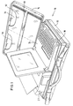
- Figure 1 is a briefly arranged briefcase arranged in perspective 10 with a bottom shell part 12 and an opened Lid shell part 14 shown.
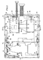
- the shaped body 16 shown in Figure 2 is used in plan view.
- This molded body 16 has a variety of recordings and Wells for various electronic devices. Characteristic for the molded body 16 is the fact that it is two overhead receiving areas 18, 20 for a printer 21 and a PC notebook 24 has. Under these two reception areas 18, 20 are a plurality of receiving recesses in the molded body 16 for a modem, a 3.5 "diskette drive, for cables, for a telephone data interface, for a basic device Wireless phones and trained for the power supplies.
- the receiving recesses 22, 23 for the main power supply in Figure 2 indicated at 26
- the PC power supply which in Figure 2 is indicated at 28.
- Both recesses 22, 23 are below of the receiving area 20 for the PC notebook 24.
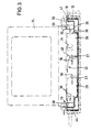
- the PC notebook 24 has an area, ie. H. not continuous Recording area within the receiving area 20, which from the top ends of four arranged substantially at right angles Support points in the form of ridges or knobs 30 put together. As can be seen from Figure 3, point the knobs 30 or ridges 30 to such a height that the Bottom side 32 of the PC notebook 24 above the power supply units 26, 28 is arranged.
- the main power supply 26 that the peripheral devices with the required operating voltages supplied with a fan 34 for generating a cooling air flow (see arrows 36).
- the blower 34 is inside the main power supply 26 is arranged.
- the main power supply 26 has one inlet indicated at 38 and one indicated at 40 Outlet on. Cooling air is sucked in through the inlet 38 and through the main power supply 26 flows through and through its outlet 40 comes out again. This cooling air blows, as in the figures shown, then further past the PC power supply 28. She strokes but also along the bottom 32 of the PC notebook, too to cool this.
- the receiving surface in the form of the elevations 30 not formed all around and does not extend over the entire bottom 32 of the PC notebook 24.
- the peripheral area of the PC notebook between a distance is provided between this and the molded body 16.
- a passage 42 which serves to admit air.
- a passage 44 which the Exhausts the cooling air and thus acts as an outlet.
- Figure 3 shows the cooling air flow profile, consequently cooling air from outside the bottom shell half 12 via the inlet 42 air in sucked in the recording area 20 below the PC notebook 24 flows through the main power supply 26, emerges from it, to then the PC power supply 28 and the bottom To flow around 32 of the PC notebook 24, and then over the To exit outlet 44.
- Hard case 10 for a notebook 24 with peripheral and Telecommunication devices e.g. printer 21
- peripheral and Telecommunication devices e.g. printer 21
- shock absorbers in the form of spring-elastic parts 50 (especially rubber stoppers) on which the devices (Notebook and printer) rest.
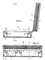
- the parts 50 are in holes of the Shaped body 16 inserted and protrude upwards (see Figs. 4 and 5).
- the lid shell part 12 of the case 10 is one Paper storage cassette 52 with two trays 54 inserted. This cassette 52 is against by an elastic band 56 unwanted folding out of the cover shell part 12 held. Behind the cassette 52 is between the latter and the cover part 14 an elastically compliant lining plate 58 (elastic Damping layer) arranged.
- the cassette 52 is closed Condition of the case 10 to that received by the molded part 16 Devices (notebook 24 and printer 21) on, and under mechanical preload resulting from the elastic deformation (Compression) of the plastic cassette 52 and the elastic compression the lining plate 58 is caused.
- the devices on both large sides of the case 10 (below the shock absorbers 50 and above the cassette 52 and the lining plate 58) spring-loaded and thus shock-absorbing.
- the devices are protected from vibrations by the fact that they on the one hand are spaced from the side walls of the case 10 and on the other hand the plastic molded body 16 in this Distance area acts resilient.
Abstract
Description
Die Erfindung betrifft eine Aufnahmevorrichtung für einen tragbaren PC, insbesondere eine Notebook, und Peripherie-Einrichtungen wie einen Drucker und Telekommunikationsvorrichtungen, nach dem Oberbegriff des Anspruchs 1, wie aus DE-U-93 02 359 bekannt.The invention relates to a receiving device for a portable PC, especially a notebook, and peripheral devices such as a printer and telecommunications devices, according to the preamble of claim 1, as known from DE-U-93 02 359.
Im Handel erhältlich sind tragbare Aufnahmevorrichtungen für Personal-Computer (PC), bei denen es sich insbesondere um sogenannte Notebooks handelt. Die Aufnahmevorrichtung ist dabei zumeist in Form eines Koffers, und zwar eines Hartschalen-Aktenkoffers ausgebildet, in dessen einer Schalenhälfte der tragbare PC sowie Peripherie-Einrichtungen, insbesondere ein Drucker, und Telekommunikationseinrichtungen, wie beispielsweise ein Modem und ein Funktelefon bzw. dessen Basisgerät, untergebracht sind. Bei Anordnung des PC und seiner Peripherie-Einrichtungen wird im Regelfall ein Formkörper in Form einer tiefgezogenen biegesteifen Folie eingesetzt, der mit Vertiefungen und Aufnahmen für die einzelnen Einrichtungen und den PC ausgestattet ist. Zur Energieversorgung der Peripherie-Einrichtungen und des PC wird bisher ein gemeinsames Netzteil verwendet, das unterhalb des PC oder, anders ausgedrückt, innerhalb der Aufnahmevorrichtung untergebracht ist. Das Netzteil übernimmt neben der Aufgabe der Energieversorgung auch die Aufgabe eines Ladegerätes zum Aufladen der Akkus des PC und der Peripherie-Einrichtungen, sofern diese akkubetrieben sind, wie dies beispielsweise bei dem Drucker der Fall ist. In der Praxis hat sich gezeigt, daß es mitunter zu Hitzestaus innerhalb der Aufnahmevorrichtung kommt, die durch den PC selbst und die Peripherie-Einrichtungen, nicht zuletzt aber auch durch das Netzteil hervorgerufen sind. Portable cradles for personal computers are commercially available (PC), which are so-called Notebooks. The receiving device is mostly in Shaped like a suitcase, namely a hard-shell briefcase, in one half of the shell the portable PC as well Peripheral devices, in particular a printer, and telecommunication devices, such as a modem and a Radio telephone or its base unit are housed. By arrangement of the PC and its peripheral devices is usually a molded body in the form of a deep-drawn rigid Foil used, with recesses and receptacles for each Facilities and the PC is equipped. For energy supply of the peripheral devices and the PC is so far shared power supply that is below the PC or, otherwise expressed, is housed within the cradle. The power supply takes on the task of power supply also the task of a charger for charging the batteries of the PC and the peripheral devices, if they are battery operated are, as is the case with the printer, for example. In Practice has shown that there can sometimes be heat build-up inside the cradle that comes through the PC itself and the peripheral devices, not least because of that Power supply are caused.
Aus DE-U-93 02 359 ist eine Aufnahmevorrichtung für einen tragbaren PC sowie Peripherie-Einrichtungen bekannt, die ein an das Spannungsnetz anschließbares Hauptnetzteil zur Erzeugung der für die Peripherie-Einrichtungen erforderlichen Betriebsspannungen aus der Netzspannung aufweist. Ferner ist ein ebenfalls an das Spannungsnetz anschließbares separates PC-Netzteil der zur Erzeugung für den PC erforderlichen Betriebsspannungen vorgesehen. Beide Netzteile sind unterhalb einer Grundplatte angeordnet, auf welcher sich der PC befindet.From DE-U-93 02 359 is a receiving device for a portable PC as well as peripheral devices known to the one Mains power supply connectable to generate the for the peripheral devices require operating voltages from the mains voltage. Furthermore, one is also to the Power supply can be connected to a separate PC power supply Generation provided for the operating voltages required for the PC. Both power supplies are below a base plate arranged on which the PC is located.
Aus DE-A-31 21 906 ist eine Datenverarbeitungsanlage in Form einer Registrierkasse bekannt, die mit mehreren peripheren Zusatzgeräten versehen ist. Innerhalb der Datenverarbeitungsanlage ist ein Netzteil mit einem Gebläse angeordnet, das Kühlluft ansaugt, wobei diese Kühlluft an den peripheren Zusatzgeräten und den einzelnen Baugruppen der Datenverarbeitungsanlage vorbeigeführt wird. Die gesamte Datenverarbeitungsanlage ist in einem Gehäuse untergebracht. DE-A-31 21 906 is a data processing system in the form a cash register known with several peripheral Additional devices is provided. Within the data processing system is a power supply unit with a blower, the cooling air sucks in, this cooling air at the peripheral accessories and the individual components of the data processing system is led past. The entire data processing system is in housed in a housing.
Der Erfindung liegt die Aufgabe zugrunde, eine Aufnahmevorrichtung für einen tragbaren PC und dessen Peripherie-Einrichtungen zu schaffen, bei der es auch bei engster Unterbringung vom PC und dessen Peripherie-Einrichtungen nicht zu Problemen infolge mechanischer Erschütterungen und einer Überhitzung kommen kann.The invention has for its object a receiving device for a portable PC and its peripheral equipment to create, even with the closest accommodation from the PC and its peripherals do not cause problems as a result mechanical shocks and overheating can occur.
Zur Lösung dieser Aufgabe wird mit der Erfindung eine Aufnahmevorrichtung mit den Merkmalen des Anspruchs 1 vorgeschlagen. Vorteilhafte Weiterbildungen ergeben sich aus den Unteransprüchen.To achieve this object, the invention provides a receiving device proposed with the features of claim 1. Beneficial Further training results from the subclaims.
Die erfindungsgemäße Aufnahmevorrichtung umfaßt ein Hauptnetzteil zur Erzeugung der für die Peripherie-Einrichtungen erforderlichen Betriebsspannungen aus der Netzspannung und ein separates PC-Netzteil zur Erzeugung der für den PC erforderlichen Betriebsspannungen. Beide Netzteile sind über ein Kabel mit dem Spannungsnetz verbindbar; in dieser Betriebsart befindet sich der PC nicht im Akku-Betrieb, sondern wird von der Netzspannung versorgt. Ist die Aufnahmevorrichtung oder, genauer gesagt, sind die beiden Netzteile nicht mit dem Spannungsnetz verbunden, so arbeiten sämtliche Einrichtungen über Akkus. Bei der erfindungsgemäßen Aufnahmevorrichtung sind ferner die beiden Netzteile unterhalb des PC angeordnet. Dies geschieht in erster Linie aus Platzersparnisgründen. Die erfindungsgemäße Aufnahmevorrichtung ist darüber hinaus mit einer Kühlluftströmungs-Erzeugungsvorrichtung versehen. Diese Kühlluftströmungs-Erzeugungsvorrichtung erzeugt eine Kühlluftströmung zum Kühlen des Hauptnetzteiles. Erfindungsgemäß ist das PC-Netzteil derart angeordnet, daß es der Kühlluftströmung ausgesetzt ist. Vorzugsweise handelt es sich bei der Kühlluftströmungs-Erzeugungsvorrichtung um ein Gebläse, das zweckmäßigerweise im Hauptnetzteil selbst untergebracht ist. In diesem Fall ist das Hauptnetzteil mit einem Lufteinlaß und einem Luftauslaß versehen.The receiving device according to the invention comprises a main power supply to generate the necessary for the peripheral devices Operating voltages from the mains voltage and a separate PC power supply to generate the operating voltages required for the PC. Both power supplies are connected to the voltage network via a cable connectable; the PC is in this mode not in battery operation, but is supplied by the mains voltage. Is the cradle or, more specifically, the both power supplies are not connected to the power grid, so work all devices via batteries. In the case of the invention Recording device are also the two power supplies below of the PC arranged. This is done primarily to save space. The receiving device according to the invention is furthermore with a cooling air flow generating device Mistake. This cooling air flow generating device generates a cooling air flow to cool the main power supply. According to the invention the PC power supply is arranged such that it is the cooling air flow is exposed. It is preferably the Cooling air flow generating device around a fan that is conveniently housed in the main power supply itself. In In this case the main power supply is with one air inlet and one Provide air outlet.
Bei der erfindungsgemäßen Aufnahmevorrichtung werden der PC sowie das dem PC zugeordnete PC-Netzteil durch eine modulare Umluftanlage (Kühlluftströmungs-Erzeugungsvorrichtung) ständig mit Frischluft versorgt. Der Vorteil dieser Maßnahme besteht darin, daß die Abwärme des PC unterhalb desselben ständig abgeführt wird, sobald der PC nicht akkubetrieben, sondern von seinem PC-Netzteil stromversorgt wird. Damit werden Wärmestaus innerhalb der Aufnahmevorrichtung vermieden. Wegen der platzsparenden Unterbringung der Komponenten des Hauptnetzteiles und der Vielzahl von anschließbaren Peripherie-Einrichtungen sowie Telekommunikationseinrichtungen ist es in jedem Fall zweckmäßig, das Hauptnetzteil selbst zu kühlen. Die Kühlluft kühlt aber bei der erfindungsgemäßen Aufnahmevorrichtung nicht nur das Hauptnetzteil, sondern wird auch an dem PC-Netzteil und zweckmäßigerweise auch an der den beiden Netzteilen zugewandten Unterseite des PC entlang geführt. Damit wird die Kühlluftströmung insoweit mehrfach zum Kühlen ausgenutzt.In the recording device according to the invention, the PC and the PC power supply assigned to the PC through a modular air recirculation system (Cooling air flow generating device) constantly with Fresh air supplied. The advantage of this measure is that the waste heat of the PC is constantly dissipated below it is as soon as the PC is not battery operated, but from its PC power supply is powered. This will heat up inside avoided the cradle. Because of the space-saving accommodation the components of the main power supply and the multitude of connectable peripheral devices as well as telecommunication devices it is advisable in any case, the main power supply cool yourself. The cooling air cools in the invention Cradle not just the main power supply, but is also on the PC power supply and expediently also along the bottom of the PC facing the two power supplies guided. The cooling air flow thus becomes multiple used for cooling.
Für die Anordnung der Netzteile und des PC ist es von untergeordneter Bedeutung, wo sich innerhalb des Kühlluftstroms diese Einheiten befinden. So ist es beispielsweise denkbar, daß beide Netzteile stromab oder stromauf der Kühlluftströmungs-Erzeugungsvorrichtung angeordnet sind. Schließlich ist es möglich, daß ein Netzteil stromauf und das andere stromab der Kühlluftströmungs-Erzeugungsvorrichtung angeordnet ist. It is of secondary importance for the arrangement of the power supplies and the PC Meaning where these units are within the cooling air flow are located. For example, it is conceivable that both Power supplies downstream or upstream of the cooling air flow generating device are arranged. Finally, it is possible that a Power supply upstream and the other downstream of the cooling air flow generating device is arranged.
Erfindungsgemäß ist die Aufnahmevorrichtung ferner mit einem biegesteifen Formkörper aus insbesondere einer tiefgezogenen Folie versehen. Dieser Formkörper weist mehrere Aufnahmebereiche und Aufnahmevertiefungen für den PC und die Peripherie-Einrichtungen sowie die Netzteile auf. An den Formkörper sind überdies ein Lufteinlaß zum Einlassen von Luft in den Aufnahmebereich für den PC unterhalb desselben und ein Luftauslaß zum Auslassen von Luft aus dem Aufnahmebereich unterhalb des PC ausgebildet. Diese Luftein- und -auslässe bilden sich dadurch, daß der Aufnahmebereich für den PC eine unterbrochene, d. h. nicht umlaufend geschlossene Aufnahmefläche für den PC aufweist, so daß zwischen PC und Formkörper der Lufteinlaß und der Luftauslaß in Form von spaltartigen Öffnungen oder Durchlässen verbleibt. Die Aufnahmevorrichtung bzw. der Formkörper benötigt also keine Öffnungen oder dergleichen in ihren bzw. seinen Außenwänden. Vorzugsweise liegen der Lufteinlaß und der Luftauslaß an einander gegenüberliegenden Seiten des PC, so daß die Kühlluftströmung sich entlang der Unterseite des PC über dessen Breite bzw. Länge erstreckt. Der Formkörper ist zweckmäßigerweise in die eine Schalenhälfte eines Hartschalenkoffers, insbesondere eines Aktenkoffers, einsetzbar.According to the invention, the receiving device is also provided with a Rigid molded body made in particular of a deep-drawn Provided foil. This molded body has several receiving areas and recesses for the PC and peripheral equipment as well as the power supplies. Are on the molded body moreover an air inlet for admitting air into the Recording area for the PC below it and an air outlet to release air from the recording area below the PC educated. These air inlets and outlets are formed by that the recording area for the PC is an interrupted, i.e. H. has a circumferentially closed mounting area for the PC, so that between the PC and molded body the air inlet and the air outlet remains in the form of gap-like openings or passages. The receiving device or the shaped body therefore requires no openings or the like in her or his outer walls. The air inlet and the air outlet are preferably present opposite sides of the PC so that the cooling air flow along the bottom of the PC across its width or length extends. The molded body is advantageously in the a shell half of a hard case, in particular one Briefcase, can be used.
Aus Gründen des Schutzes des PCs und der Peripherie-Geräte gegen Beschädigungen durch (mechanische) Erschütterungen sollten der PC und die Peripherie-Geräte auf elastischen Auflageflächen ruhen.For the sake of protecting the PC and the Peripheral devices against damage from (mechanical) The PC and peripheral devices should be jarred resilient support surfaces.
Mit der Erfindung wird also vorgeschlagen, die elastischen Auflageflächen für den PC nicht durchgehend auszubilden sondern lediglich bereichs- bzw. punktweise, wobei in den Bereichen außerhalb der elastischen Auflageflächen Zwischenräume zwischen dem PC und dem Formkörper verbleiben. Diese Zwischenräume dienen zum Ansaugen und Abführen von das PC-Netzteil sowie das Hauptnetzteil kühlender Kühlluft.The invention therefore proposes the elastic contact surfaces not to train continuously for the PC but only in areas or points, whereby in the areas outside of the elastic contact surfaces gaps between the PC and the molded body remain. These spaces serve for suction and discharge of the PC power supply and the main power supply cooling cooling air.
Gemäß einer weiteren vorteilhaften Ausgestaltung der Erfindung ist der Formkörper mit elastisch ausgebildeten Auflagebereichen für den Drucker versehen.According to a further advantageous embodiment of the invention is the molded body with elastic support areas for the printer.
Zweckmäßigerweise ist eine elastisch ausgebildete Abdeckung zur Anlage an der dem Formkörper abgewandten Oberseite zumindest von Notebook und/oder Drucker vorgesehen. Bei dieser Abdeckung handelt es sich insbesondere um eine elastische Kassette und/oder eine elastische Dämpfungsschicht.An elastic cover is expediently for System on the upper side facing away from the molded body at least from Notebook and / or printer provided. With this cover it is in particular an elastic cassette and / or an elastic damping layer.
Nachfolgend wird anhand der Figuren ein Ausführungsbeispiel der Erfindung näher erläutert. Im einzelnen zeigen:
- Fig. 1
- eine perspektivische Darstellung eines Hartschalen-Aktenkoffers in aufgeklapptem Zustand mit in der Bodenschalenhälfte angeordnetem Notebook und Drucker,
- Fig. 2
- eine Draufsicht auf einen in der Bodenschalenhälfte des Koffers gemäß Fig. 1 eingesetzten Formkörper zur Aufnahme des Notebooks, des Druckers, der Netzteile und der übrigen Peripherie-Geräte für den PC sowie diverser Telekommunikationseinrichtungen wie Modem, etc. und
- Fig. 3
- einen Schnitt entlang der Linie III - III der Fig. 2 durch den Formkörper mit strich-punktiert angedeutetem Notebook und Netzteilen zur Verdeutlichung der sich unterhalb des Notebooks einstellenden Kühlluftströmung.
- Fig. 4
- einen Schnitt durch den Koffer im aufgeklappten Zustand und
- Fig. 5
- eine Schnittansicht in der Ebene V-V der Fig. 4.
- Fig. 1
- 1 shows a perspective illustration of a hard-shell briefcase in the opened state with a notebook and printer arranged in the bottom shell half,
- Fig. 2
- a top view of a molded body used in the bottom half of the case according to FIG. 1 for receiving the notebook, the printer, the power supplies and the other peripheral devices for the PC and various telecommunication devices such as modems, etc. and
- Fig. 3
- a section along the line III - III of Fig. 2 through the molded body with dash-dotted hinted notebook and power supplies to illustrate the cooling air flow below the notebook.
- Fig. 4
- a section through the case in the opened state and
- Fig. 5
- a sectional view in the plane VV of FIG. 4th
In Figur 1 ist perspektivisch ein liegend angeordneter Aktenkoffer
10 mit einem Bodenschalenteil 12 und einem aufgeklappten
Deckelschalenteil 14 dargestellt. In den Bodenschalenteil 12 ist
der in Figur 2 in Draufsicht dargestellte Formkörper 16 eingesetzt.
Dieser Formkörper 16 weist eine Vielzahl von Aufnahmen und
Aufnahmevertiefungen für diverse elektronische Geräte auf. Charakteristisch
für den Formkörper 16 ist die Tatsache, daß er zwei
obenliegende Aufnahmebereiche 18, 20 für einen Drucker 21 und ein
PC-Notebook 24 aufweist. Unter diesen beiden Aufnahmebereichen
18, 20 sind in dem Formkörper 16 eine Vielzahl von Aufnahmevertiefungen
für ein Modem, ein 3,5"-Disketten-Laufwerk, für Kabel,
für eine Telefon-Datenschnittstelle, für ein Basisgerät eines
Drahtlos-Telefons und für die Netzteile ausgebildet. Ferner ist
der Formkörper mit Aufnahmen für Seriell- und Parallelstecker,
für Netzeingangsstecker und für einige Bürobedarfsartikel, insbesondere
für eine Heftmaschine und für Heftklammern, ausgestattet.
Von Interesse im Rahmen des hier zu beschreibenden Aktenkoffers
10 sind die Aufnahmevertiefungen 22, 23 für das Hauptnetzteil (in
Figur 2 bei 26 angedeutet) und das PC-Netzteil, das in Figur 2
bei 28 angedeutet ist. Beide Vertiefungen 22, 23 sind unterhalb
des Aufnahmebereichs 20 für das PC-Notebook 24 ausgebildet. Das
PC-Notebook 24 weist eine bereichsweise, d. h. nicht durchgehende
Aufnahmefläche innerhalb des Aufnahmebereichs 20 auf, die sich
aus den oberen Enden von vier im wesentlichen rechtwinklig angeordneten
Auflagepunkten in Form von Erhöhungen oder Noppen 30
zusammensetzt. Wie man anhand von Figur 3 erkennen kann, weisen
die Noppen 30 oder Erhöhungen 30 eine solche Höhe auf, daß die
Unterseite 32 des PC-Notebooks 24 oberhalb der Netzteile 26, 28
angeordnet ist.In Figure 1 is a briefly arranged briefcase arranged in
Wie in den Figuren ferner angedeutet, ist das Hauptnetzteil 26,
das die Peripherie-Geräte mit den erforderlichen Betriebsspannungen
versorgt, mit einem Gebläse 34 zur Erzeugung einer Kühlluftströmung
(siehe Pfeile 36) versehen. Das Gebläse 34 ist innerhalb
des Hauptnetzteiles 26 angeordnet. Das Hauptnetzteil 26 weist
einen bei 38 angedeuteten Einlaß und einen bei 40 angedeuteten
Auslaß auf. Über den Einlaß 38 wird Kühlluft angesaugt, die durch
das Hauptnetzteil 26 hindurchströmt und über dessen Auslaß 40
wieder heraustritt. Diese Kühlluft streicht, wie in den Figuren
gezeigt, dann weiter an dem PC-Netzteil 28 vorbei. Sie streicht
aber auch an der Unterseite 32 des PC-Notebooks entlang, um auch
dieses zu kühlen.As further indicated in the figures, the
Wie in den Figuren 2 und 3 zu erkennen ist, ist die Aufnahmefläche
in Form der Erhebungen 30 nicht umlaufend ausgebildet und
erstreckt sich nicht über die gesamte Unterseite 32 des PC-Notebooks
24. Insbesondere sind im Randbereich des PC-Notebooks zwischen
diesem und dem Formkörper 16 ein Abstand vorgesehen. An dem
dem Lufteinlaß 38 des Hauptnetzteiles 26 nächstliegenden Rand des
PC-Notebooks 24 und dem Formkörper 16 bildet sich ein Durchlaß
42, der dem Einlaß von Luft dient. An dem diesem Lufteinlaß 42
gegenüberliegenden Ende des Formkörpers 16 bildet sich zwischen
diesem und dem PC-Notebook 24 wiederum ein Durchlaß 44, der der
Abführung der Kühlluft dient und damit als Auslaß fungiert. Figur
3 zeigt den Kühlluftströmungsverlauf, demzufolge Kühlluft von
außerhalb der Bodenschalenhälfte 12 über den Einlaß 42 Luft in
den Aufnahmebereich 20 unterhalb des PC-Notebooks 24 angesaugt
wird, durch das Hauptnetzteil 26 hindurchströmt, aus diesem heraustritt,
um anschließend das PC-Netzteil 28 sowie die Unterseite
32 des PC-Notebooks 24 zu umströmen, und anschließend über den
Auslaß 44 auszutreten.As can be seen in Figures 2 and 3, the receiving surface
in the form of the
Abschließend soll noch auf ein weiteres Merkmal des
Hartschalen-Koffers 10 für ein Notebook 24 mit Peripherie- und
Telekommunikationsgeräten (z.B. Drucker 21) eingegangen werden,
und zwar auf die federnde und damit schock-absorbierende Unterbringung
der Geräte in dem Koffer 10.Finally, another feature of the
Zu diesem Zweck weist der in den Bodenschalenteil 12 des Koffers
10 eingesetzte (Tiefziehfolien-)Formkörper 16 an seinen Auflagepunkten
30 Schock-Absorber in Form von feder-elastischen Teilen
50 (insbesondere Gummi-Stopfen) auf, auf denen die Geräte
(Notebook und Drucker) ruhen. Die Teile 50 sind in Löcher des
Formkörpers 16 eingesteckt und stehen nach oben über (siehe Fign.
4 und 5). In dem Deckelschalenteil 12 des Koffers 10 ist eine
Papieraufbewahrungskassette 52 mit zwei Fächern 54 eingesetzt.
Diese Kassette 52 wird durch ein elastisches Band 56 gegen ein
ungewolltes Herausklappen aus dem Deckelschalenteil 12 gehalten.
Hinter der Kassette 52 ist zwischen dieser und dem Deckelteil 14
eine elastisch nachgiebige Auskleidungsplatte 58 (elastische
Dämpfungsschicht) angeordnet. For this purpose, it points into the
Wie in Fig. 5 zu erkennen ist, liegt die Kassette 52 in geschlossenem
Zustand des Koffers 10 auf den von dem Formteil 16 aufgenommenen
Geräten (Notebook 24 und Drucker 21) auf, und zwar unter
mechanischer Vorspannung, die infolge der elastischen Verformung
(Stauchung) der Kunststoff-Kassette 52 und der elastischen Verdichtung
der Auskleidungsplatte 58 hervorgerufen ist. Damit sind
die Geräte an beiden großflächigen Seiten des Koffers 10 (unten
die Schockabsorber 50 und oben die Kassette 52 und die Auskleidungsplatte
58) federnd und damit schockabsorbierend gelagert.
Gegen seitlich auf den geschlossenen Koffer 10 einwirkende
Erschütterungen sind die Geräte dadurch geschützt, daß sie
einerseits von den Seitenwänden des Koffers 10 beabstandet sind
und andererseits der Kunststoff-Formkörper 16 in diesem
Abstandsbereich federnd wirkt.As can be seen in Fig. 5, the
Claims (11)
- An accommodating device for a portable PC, particularly for a notebook, and for peripheral devices such as a printer (21) and telecommunications devices, comprisingcharacterized ina principle power-supply unit (26) connectible to the voltage network, for generating the required operating voltages for the peripheral devices from the network voltage,a separate PC power supply unit (28) connectible to the voltage network, for generating the required operational voltages for the PC (24),both of said power supply units (26,28) being arranged underneath the PC (24),that a cooling air flow generator (34) is provided for generating a cooling air flow for cooling the principle power-supply unit (26),that the PC power supply unit (28) is arranged in the cooling air flow,that a shaped body (16) resistant to bending is provided for accommodating the PC (24), the peripheral devices and the two power supply units (26,28),that the shaped body (16) comprises a receiving portion (20) with an interrupted, non-continuous receiving face (30) for the PC (24), provided with elastic support portions (50), such that, between the shaped body (16) and the PC (24), at least one air inlet means (42) remains underneath the PC (24) to allow air to enter the receiving portion (20), and an air outlet means (44) remains underneath the PC (24) for discharging air from the receiving portion (20), andthat deepened receiving recesses (22,23) for the two power supply units (26,28) are provided within the receiving portion (20).
- The accommodating device according to claim 1, characterized in that the cooling air flow generator (34) is a blower.
- The accommodating device according to claim 2, characterized in that the blower is accommodated in the principle power-supply unit (26) and that the principle power-supply unit (26) comprises an air inlet means (38) and an air outlet means (40).
- The accommodating device according to any one of claims 1 to 3, characterized in that the two power-supply units (26,28) are arranged downstream or upstream or the one power-supply unit (26;28) is arranged downstream and the other power-supply unit (28;26) is arranged upstream of the cooling air flow generator (34).
- The accommodating device according to any one of claims 1 to 4, characterized in that the cooling air flow generator (34) is arranged in such a manner that the cooling air flow streams along the bottom side (32) of the PC (24) facing towards the power supply units (26,28).
- The accommodating device according to any one of claims 1 to 5, characterized in that the PC (24), the two power supply units (26,28), the cooling air flow generator (34) and the peripheral devices are accommodated in a suitcase, particularly in a file case (10).
- The accommodating device according to any one of claims 1 to 6, characterized in that the shaped body (16) can be inserted into a half-shell (12) of a suitcase, particularly of a file case (10).
- The accommodating device according to any one of claims 1 to 7, characterized in that the two power supply units (26,28) are individual modules and that the two power supply units (26,28) together with the PC (24) form a modular air-circulating means for cooling and venting its constituent components.
- The accommodating device according to any one of claims 1 to 8, characterized in that the shaped body (16) comprises elastic support portions (50) for the printer (21).
- The accommodating device according to any one of claims 1 to 9, characterized in that an elastically resilient cover (52,58) is provided for abutment on the upper side of at least the notebook (24) and/or the printer (21) which is facing away from the shaped body (16).
- The accommodating device according to claim 11, characterized in that the cover (52,58) is an elastic cassette (52) and/or an elastic damping layer (58).
Applications Claiming Priority (3)
| Application Number | Priority Date | Filing Date | Title |
|---|---|---|---|
| DE9410720U DE9410720U1 (en) | 1994-07-02 | 1994-07-02 | Portable PC cradle |
| DE9410720U | 1994-07-02 | ||
| PCT/EP1995/002566 WO1996001447A1 (en) | 1994-07-02 | 1995-07-03 | Container for a portable pc |
Publications (2)
| Publication Number | Publication Date |
|---|---|
| EP0769166A1 EP0769166A1 (en) | 1997-04-23 |
| EP0769166B1 true EP0769166B1 (en) | 1998-02-04 |
Family
ID=6910636
Family Applications (1)
| Application Number | Title | Priority Date | Filing Date |
|---|---|---|---|
| EP95925809A Expired - Lifetime EP0769166B1 (en) | 1994-07-02 | 1995-07-03 | Container for a portable pc |
Country Status (7)
| Country | Link |
|---|---|
| US (1) | US5831823A (en) |
| EP (1) | EP0769166B1 (en) |
| AT (1) | ATE163098T1 (en) |
| CZ (1) | CZ380496A3 (en) |
| DE (2) | DE9410720U1 (en) |
| SK (1) | SK169096A3 (en) |
| WO (1) | WO1996001447A1 (en) |
Families Citing this family (25)
| Publication number | Priority date | Publication date | Assignee | Title |
|---|---|---|---|---|
| DE29512818U1 (en) * | 1995-08-09 | 1995-10-19 | Parat Werk Schoenenbach Gmbh | Computer system case |
| DE29604648U1 (en) * | 1996-03-13 | 1996-09-12 | Hoedl Fritz Dr | Recording device for a portable computer, in particular a laptop or a notebook |
| SG74010A1 (en) * | 1996-06-14 | 2000-07-18 | Compaq Computer Corp | Serial bus hub |
| US6118654A (en) | 1997-04-22 | 2000-09-12 | Intel Corporation | Heat exchanger for a portable computing device and docking station |
| DE29711974U1 (en) * | 1997-07-08 | 1997-09-18 | Hoedl Fritz Dr | Storage device for a portable computer, in particular a laptop or a notebook |
| TW341344U (en) * | 1997-08-07 | 1998-09-21 | Mustek Systems Inc | A scanner file carrier |
| US20010040788A1 (en) | 1998-09-30 | 2001-11-15 | O'connor Michael | Thermal connector for joining mobile electronic devices to docking stations |
| KR100620179B1 (en) * | 1998-10-08 | 2007-07-09 | 엘지전자 주식회사 | Error Correction Method According to Playback Speed of Optical Disc |
| US6094347A (en) * | 1999-01-08 | 2000-07-25 | Intel Corporation | Airflow heat exchanger for a portable electronic device and port replicator, docking station, or mini-docking station |
| JP2000216558A (en) * | 1999-01-21 | 2000-08-04 | Toshiba Corp | Electronic device, expansion device attachable thereto, and electronic equipment system provided therewith |
| AT408036B (en) * | 1999-04-15 | 2001-08-27 | A & D Computersysteme Und Baut | Case for receiving at least one electrical/electronic device that generates heat during operation |
| WO2002070373A1 (en) * | 2001-03-06 | 2002-09-12 | Samsonite Corporation | Carrying case for a laptop computer |
| JP2004530211A (en) * | 2001-05-07 | 2004-09-30 | ジ・アイ・ディ・イー・エイ・コーポレイション | Portable office having a removable computer workstation and a shock isolation system therefor |
| US7035093B2 (en) * | 2003-02-03 | 2006-04-25 | Maxvision Corporation | Packaging mechanism for a portable computer |
| US20050213302A1 (en) * | 2004-03-29 | 2005-09-29 | Hao-Cheng Lin | Heat-dissipating device for a portable computer |
| US8155142B2 (en) * | 2006-03-16 | 2012-04-10 | Exceptional Innovation Llc | Network based digital access point device |
| US8209398B2 (en) * | 2006-03-16 | 2012-06-26 | Exceptional Innovation Llc | Internet protocol based media streaming solution |
| US8001219B2 (en) * | 2006-03-16 | 2011-08-16 | Exceptional Innovation, Llc | User control interface for convergence and automation system |
| US8725845B2 (en) * | 2006-03-16 | 2014-05-13 | Exceptional Innovation Llc | Automation control system having a configuration tool |
| WO2007124453A2 (en) | 2006-04-20 | 2007-11-01 | Exceptional Innovation Llc | Touch screen for convergence and automation system |
| US7667968B2 (en) * | 2006-05-19 | 2010-02-23 | Exceptional Innovation, Llc | Air-cooling system configuration for touch screen |
| US7962130B2 (en) | 2006-11-09 | 2011-06-14 | Exceptional Innovation | Portable device for convergence and automation solution |
| US8705233B2 (en) * | 2008-03-29 | 2014-04-22 | Dell Products L.P. | System and method for portable information handling system thermal shield |
| US8050032B2 (en) * | 2009-09-22 | 2011-11-01 | Trang Brian T | Laptop elevation device |
| US8139357B2 (en) * | 2009-09-22 | 2012-03-20 | Trang Brian T | Laptop elevation device |
Family Cites Families (10)
| Publication number | Priority date | Publication date | Assignee | Title |
|---|---|---|---|---|
| US4084213A (en) * | 1977-02-22 | 1978-04-11 | Modern Controls, Inc. | Portable keyboard/display terminal |
| AT374034B (en) * | 1980-07-18 | 1984-03-12 | Siemens Ag Oesterreich | COMPONENT ARRANGEMENT FOR THE CONTROL UNIT OF A DATA PROCESSING SYSTEM |
| DE3438820A1 (en) * | 1984-10-23 | 1986-04-24 | Frank & Britting Elektronik Entwicklungsgesellschaft mbH, 7529 Forst | Bulk memory replacement unit for a table-top computer |
| US5305183A (en) * | 1991-07-09 | 1994-04-19 | Edison Welding Institute | Portable personal computer with passive backplane having a doublesided staggered connector array |
| DE9112987U1 (en) * | 1991-10-18 | 1991-12-19 | Bds, Buero- Und Datensystemhaus Gmbh, 3000 Hannover, De | |
| DE4220051C2 (en) * | 1992-06-20 | 1996-12-05 | Selig Erik | Communication briefcase |
| DE9302359U1 (en) * | 1993-02-18 | 1993-05-13 | Transtel Gmbh, 2000 Hamburg, De | |
| DE9315806U1 (en) * | 1993-10-16 | 1994-01-05 | Becker Dieter | suitcase |
| US5552957A (en) * | 1994-09-09 | 1996-09-03 | International Business Machines Corporation | Portable computer field kit |
| US5704212A (en) * | 1996-09-13 | 1998-01-06 | Itronix Corporation | Active cooling system for cradle of portable electronic devices |
-
1994
- 1994-07-02 DE DE9410720U patent/DE9410720U1/en not_active Expired - Lifetime
-
1995
- 1995-07-03 SK SK1690-96A patent/SK169096A3/en unknown
- 1995-07-03 AT AT95925809T patent/ATE163098T1/en not_active IP Right Cessation
- 1995-07-03 DE DE59501423T patent/DE59501423D1/en not_active Expired - Fee Related
- 1995-07-03 EP EP95925809A patent/EP0769166B1/en not_active Expired - Lifetime
- 1995-07-03 CZ CZ963804A patent/CZ380496A3/en unknown
- 1995-07-03 US US08/765,354 patent/US5831823A/en not_active Expired - Fee Related
- 1995-07-03 WO PCT/EP1995/002566 patent/WO1996001447A1/en not_active Application Discontinuation
Also Published As
| Publication number | Publication date |
|---|---|
| CZ380496A3 (en) | 1998-09-16 |
| ATE163098T1 (en) | 1998-02-15 |
| DE9410720U1 (en) | 1995-11-02 |
| SK169096A3 (en) | 1997-11-05 |
| US5831823A (en) | 1998-11-03 |
| DE59501423D1 (en) | 1998-03-12 |
| WO1996001447A1 (en) | 1996-01-18 |
| EP0769166A1 (en) | 1997-04-23 |
Similar Documents
| Publication | Publication Date | Title |
|---|---|---|
| EP0769166B1 (en) | Container for a portable pc | |
| DE69731448T2 (en) | Portable computer equipped with additional battery | |
| DE4345307C2 (en) | Portable information/word processor | |
| EP2399309B1 (en) | Electrical power storage unit for motor vehicles | |
| EP0863695A1 (en) | Apparatus housing | |
| DE102012204407A1 (en) | System at least with a hand tool kit and a construction site radio | |
| DE102012220837A1 (en) | Building construction site radio has battery housing whose sides are partially limited to be maximum of four sides, while hand tool battery is electrically coupled to battery accommodating portion | |
| EP3389116B1 (en) | Battery pack and hand-held power tool | |
| DE10318947A1 (en) | Electric hand tool with battery pack | |
| EP3608065A1 (en) | Storage device for tools | |
| EP2886006B1 (en) | Support system for modular battery unit | |
| DE102014016370A1 (en) | A system for coupling accessories to a portable electronic device | |
| DE202015103714U1 (en) | Charging station for telecommunication devices and electronic clocks | |
| DE19938104A1 (en) | Improved docking tray for customizing the exterior battery charging for notebook computers | |
| EP0898444B1 (en) | Cabinet for electrical equipment | |
| DE202014106293U1 (en) | battery pack | |
| AT402252B (en) | HAND CASE IN WHICH A PC (NOTEBOOK) DEVICE AND A PRINTER CONNECTED TO IT ARE ARRANGED | |
| EP1170891B1 (en) | Portable container for receiving a sound or light mixing console | |
| DE3933643A1 (en) | Measuring appts. with modular measuring devices - has interchangeable measuring fitted to carrier plate for insertion in standard size rack | |
| WO2022069161A1 (en) | Holding device for arrangement on a battery pack of a machine tool | |
| WO1997034215A1 (en) | Holder for a portable computer, especially a laptop or a notebook | |
| EP0458832B1 (en) | Appliance system comprising a first electrical appliance and at least a second electrical appliance coupled thereto | |
| DE202015100924U1 (en) | Tool box with a rotatable support part for tool inserts | |
| EP1037444A2 (en) | Handset for telecommunication terminals | |
| DE202021002446U1 (en) | Transport and performance bag for electronic keyboard instruments in performance situations |
Legal Events
| Date | Code | Title | Description |
|---|---|---|---|
| PUAI | Public reference made under article 153(3) epc to a published international application that has entered the european phase |
Free format text: ORIGINAL CODE: 0009012 |
|
| 17P | Request for examination filed |
Effective date: 19970111 |
|
| AK | Designated contracting states |
Kind code of ref document: A1 Designated state(s): AT BE CH DE DK ES FR GB IT LI NL PT SE |
|
| RAP1 | Party data changed (applicant data changed or rights of an application transferred) |
Owner name: UITZ, CHRISTIAN Owner name: HOEDL, FRITZ Owner name: SCHWARZINGER, VERONIKA |
|
| GRAG | Despatch of communication of intention to grant |
Free format text: ORIGINAL CODE: EPIDOS AGRA |
|
| GRAG | Despatch of communication of intention to grant |
Free format text: ORIGINAL CODE: EPIDOS AGRA |
|
| GRAH | Despatch of communication of intention to grant a patent |
Free format text: ORIGINAL CODE: EPIDOS IGRA |
|
| 17Q | First examination report despatched |
Effective date: 19970715 |
|
| GRAH | Despatch of communication of intention to grant a patent |
Free format text: ORIGINAL CODE: EPIDOS IGRA |
|
| GRAA | (expected) grant |
Free format text: ORIGINAL CODE: 0009210 |
|
| AK | Designated contracting states |
Kind code of ref document: B1 Designated state(s): AT BE CH DE DK ES FR GB IT LI NL PT SE |
|
| PG25 | Lapsed in a contracting state [announced via postgrant information from national office to epo] |
Ref country code: IT Free format text: LAPSE BECAUSE OF FAILURE TO SUBMIT A TRANSLATION OF THE DESCRIPTION OR TO PAY THE FEE WITHIN THE PRE;WARNING: LAPSES OF ITALIAN PATENTS WITH EFFECTIVE DATE BEFORE 2007 MAY HAVE OCCURRED AT ANY TIME BEFORE 2007. THE CORRECT EFFECTIVE DATE MAY BE DIFFERENT FROM THE ONE RECORDED.SCRIBED TIME-LIMIT Effective date: 19980204 Ref country code: ES Free format text: THE PATENT HAS BEEN ANNULLED BY A DECISION OF A NATIONAL AUTHORITY Effective date: 19980204 |
|
| REF | Corresponds to: |
Ref document number: 163098 Country of ref document: AT Date of ref document: 19980215 Kind code of ref document: T |
|
| REG | Reference to a national code |
Ref country code: CH Ref legal event code: NV Representative=s name: TROESCH SCHEIDEGGER WERNER AG Ref country code: CH Ref legal event code: EP |
|
| GBT | Gb: translation of ep patent filed (gb section 77(6)(a)/1977) |
Effective date: 19980206 |
|
| REF | Corresponds to: |
Ref document number: 59501423 Country of ref document: DE Date of ref document: 19980312 |
|
| ET | Fr: translation filed | ||
| PG25 | Lapsed in a contracting state [announced via postgrant information from national office to epo] |
Ref country code: PT Free format text: LAPSE BECAUSE OF FAILURE TO SUBMIT A TRANSLATION OF THE DESCRIPTION OR TO PAY THE FEE WITHIN THE PRESCRIBED TIME-LIMIT Effective date: 19980504 Ref country code: DK Free format text: LAPSE BECAUSE OF FAILURE TO SUBMIT A TRANSLATION OF THE DESCRIPTION OR TO PAY THE FEE WITHIN THE PRESCRIBED TIME-LIMIT Effective date: 19980504 |
|
| PGFP | Annual fee paid to national office [announced via postgrant information from national office to epo] |
Ref country code: AT Payment date: 19980723 Year of fee payment: 4 |
|
| PGFP | Annual fee paid to national office [announced via postgrant information from national office to epo] |
Ref country code: SE Payment date: 19980729 Year of fee payment: 4 |
|
| PG25 | Lapsed in a contracting state [announced via postgrant information from national office to epo] |
Ref country code: BE Free format text: LAPSE BECAUSE OF NON-PAYMENT OF DUE FEES Effective date: 19980731 |
|
| PLBE | No opposition filed within time limit |
Free format text: ORIGINAL CODE: 0009261 |
|
| STAA | Information on the status of an ep patent application or granted ep patent |
Free format text: STATUS: NO OPPOSITION FILED WITHIN TIME LIMIT |
|
| 26N | No opposition filed | ||
| BERE | Be: lapsed |
Owner name: UITZ CHRISTIAN Effective date: 19980731 Owner name: HODL FRITZ Effective date: 19980731 Owner name: SCHWARZINGER VERONIKA Effective date: 19980731 |
|
| PG25 | Lapsed in a contracting state [announced via postgrant information from national office to epo] |
Ref country code: AT Free format text: LAPSE BECAUSE OF NON-PAYMENT OF DUE FEES Effective date: 19990703 |
|
| PG25 | Lapsed in a contracting state [announced via postgrant information from national office to epo] |
Ref country code: SE Free format text: THE PATENT HAS BEEN ANNULLED BY A DECISION OF A NATIONAL AUTHORITY Effective date: 19990730 |
|
| PG25 | Lapsed in a contracting state [announced via postgrant information from national office to epo] |
Ref country code: LI Free format text: LAPSE BECAUSE OF NON-PAYMENT OF DUE FEES Effective date: 19990731 Ref country code: CH Free format text: LAPSE BECAUSE OF NON-PAYMENT OF DUE FEES Effective date: 19990731 |
|
| PG25 | Lapsed in a contracting state [announced via postgrant information from national office to epo] |
Ref country code: NL Free format text: LAPSE BECAUSE OF NON-PAYMENT OF DUE FEES Effective date: 20000201 |
|
| REG | Reference to a national code |
Ref country code: CH Ref legal event code: PL |
|
| EUG | Se: european patent has lapsed |
Ref document number: 95925809.6 |
|
| NLV4 | Nl: lapsed or anulled due to non-payment of the annual fee |
Effective date: 20000201 |
|
| PGFP | Annual fee paid to national office [announced via postgrant information from national office to epo] |
Ref country code: GB Payment date: 20000612 Year of fee payment: 6 |
|
| PGFP | Annual fee paid to national office [announced via postgrant information from national office to epo] |
Ref country code: FR Payment date: 20000718 Year of fee payment: 6 |
|
| PGFP | Annual fee paid to national office [announced via postgrant information from national office to epo] |
Ref country code: DE Payment date: 20000831 Year of fee payment: 6 |
|
| PG25 | Lapsed in a contracting state [announced via postgrant information from national office to epo] |
Ref country code: GB Free format text: LAPSE BECAUSE OF NON-PAYMENT OF DUE FEES Effective date: 20010703 |
|
| GBPC | Gb: european patent ceased through non-payment of renewal fee |
Effective date: 20010703 |
|
| PG25 | Lapsed in a contracting state [announced via postgrant information from national office to epo] |
Ref country code: FR Free format text: LAPSE BECAUSE OF NON-PAYMENT OF DUE FEES Effective date: 20020329 |
|
| PG25 | Lapsed in a contracting state [announced via postgrant information from national office to epo] |
Ref country code: DE Free format text: LAPSE BECAUSE OF NON-PAYMENT OF DUE FEES Effective date: 20020501 |
|
| REG | Reference to a national code |
Ref country code: FR Ref legal event code: ST |