EP0768760A1 - Current comparator - Google Patents
Current comparator Download PDFInfo
- Publication number
- EP0768760A1 EP0768760A1 EP95830420A EP95830420A EP0768760A1 EP 0768760 A1 EP0768760 A1 EP 0768760A1 EP 95830420 A EP95830420 A EP 95830420A EP 95830420 A EP95830420 A EP 95830420A EP 0768760 A1 EP0768760 A1 EP 0768760A1
- Authority
- EP
- European Patent Office
- Prior art keywords
- current
- circuit
- branch
- forced
- comparator circuit
- Prior art date
- Legal status (The legal status is an assumption and is not a legal conclusion. Google has not performed a legal analysis and makes no representation as to the accuracy of the status listed.)
- Granted
Links
- 230000000295 complement effect Effects 0.000 claims abstract description 14
- 238000010521 absorption reaction Methods 0.000 claims abstract description 7
- 238000000034 method Methods 0.000 claims description 2
- 230000000694 effects Effects 0.000 description 9
- 238000004088 simulation Methods 0.000 description 8
- 238000010586 diagram Methods 0.000 description 7
- 230000001052 transient effect Effects 0.000 description 6
- 230000003071 parasitic effect Effects 0.000 description 4
- 238000012360 testing method Methods 0.000 description 4
- 230000004044 response Effects 0.000 description 3
- 101150095530 CDS1 gene Proteins 0.000 description 2
- 101150040536 CDS2 gene Proteins 0.000 description 2
- 238000013459 approach Methods 0.000 description 2
- 230000001419 dependent effect Effects 0.000 description 2
- 238000005516 engineering process Methods 0.000 description 2
- 238000012545 processing Methods 0.000 description 2
- 238000012546 transfer Methods 0.000 description 2
- 230000007704 transition Effects 0.000 description 2
- 230000001427 coherent effect Effects 0.000 description 1
- 230000008878 coupling Effects 0.000 description 1
- 238000010168 coupling process Methods 0.000 description 1
- 238000005859 coupling reaction Methods 0.000 description 1
- 230000001934 delay Effects 0.000 description 1
- 238000011156 evaluation Methods 0.000 description 1
- 238000002347 injection Methods 0.000 description 1
- 239000007924 injection Substances 0.000 description 1
- 230000010354 integration Effects 0.000 description 1
- 230000002452 interceptive effect Effects 0.000 description 1
- 230000007246 mechanism Effects 0.000 description 1
- 238000012544 monitoring process Methods 0.000 description 1
- 238000005293 physical law Methods 0.000 description 1
- 230000035945 sensitivity Effects 0.000 description 1
- 238000000926 separation method Methods 0.000 description 1
- 239000000243 solution Substances 0.000 description 1
- 238000009966 trimming Methods 0.000 description 1
- 238000012795 verification Methods 0.000 description 1
Images


Classifications
-
- H—ELECTRICITY
- H03—ELECTRONIC CIRCUITRY
- H03F—AMPLIFIERS
- H03F3/00—Amplifiers with only discharge tubes or only semiconductor devices as amplifying elements
- H03F3/34—DC amplifiers in which all stages are DC-coupled
- H03F3/343—DC amplifiers in which all stages are DC-coupled with semiconductor devices only
- H03F3/345—DC amplifiers in which all stages are DC-coupled with semiconductor devices only with field-effect devices
-
- G—PHYSICS
- G05—CONTROLLING; REGULATING
- G05F—SYSTEMS FOR REGULATING ELECTRIC OR MAGNETIC VARIABLES
- G05F3/00—Non-retroactive systems for regulating electric variables by using an uncontrolled element, or an uncontrolled combination of elements, such element or such combination having self-regulating properties
- G05F3/02—Regulating voltage or current
- G05F3/08—Regulating voltage or current wherein the variable is dc
- G05F3/10—Regulating voltage or current wherein the variable is dc using uncontrolled devices with non-linear characteristics
- G05F3/16—Regulating voltage or current wherein the variable is dc using uncontrolled devices with non-linear characteristics being semiconductor devices
- G05F3/20—Regulating voltage or current wherein the variable is dc using uncontrolled devices with non-linear characteristics being semiconductor devices using diode- transistor combinations
- G05F3/26—Current mirrors
- G05F3/262—Current mirrors using field-effect transistors only
-
- H—ELECTRICITY
- H03—ELECTRONIC CIRCUITRY
- H03K—PULSE TECHNIQUE
- H03K5/00—Manipulating of pulses not covered by one of the other main groups of this subclass
- H03K5/22—Circuits having more than one input and one output for comparing pulses or pulse trains with each other according to input signal characteristics, e.g. slope, integral
- H03K5/24—Circuits having more than one input and one output for comparing pulses or pulse trains with each other according to input signal characteristics, e.g. slope, integral the characteristic being amplitude
- H03K5/2472—Circuits having more than one input and one output for comparing pulses or pulse trains with each other according to input signal characteristics, e.g. slope, integral the characteristic being amplitude using field effect transistors
Definitions
- the present invention relates to integrated circuits of signal processing and in particular to current comparators.
- the comparison between two currents is made by forcing the currents to be compared through the two branches of a differential (unbalance) stage circuit so as to be able to discriminate the highest (or lowest) input current by monitoring the respective voltage levels of two nodes, respectively of one and the other branch of the unbalance circuit.
- a dedicated buffer stage or several stages in cascode provide a logic signal that is representative of the result of the comparison between the two input currents, forced through the respective branches of the comparator circuit.
- Forcing the currents to be compared through the respective branches of the comparator circuit implies an absorption of these currents from a supply rail and therefore an attendant consumption which will be more or less high depending on the level of the input currents to be compared.
- the absorption and therefore the consumption depends substantially from the level of the highest current being compared which may indeed be a preestablished reference current with which to compare a certain current signal.
- the invention consists in limiting the absorption of current through the branch of the comparator circuit along which is forced the highest current to the value of the lowest current which is in turn forced through the other branch of the comparator circuit. This condition is obtained without interfering in any way on other characteristics of switching speed and sensitivity of the comparator circuit.
- the invention consists in discriminating the level of two currents while limiting the current in the branch of the unbalanced circuit through which is being forced the highest of the two currents to the value of the other (lowest) current which flows in the other branch of the unbalanced circuit.
- the circuit of the invention is able to accomplish the required comparison through operating at a current level that is limited to the value of the lowest current, without requiring the use of any switch or other digitally controlled device.
- An important aspect of the circuit of this invention is the fact that it is composed of a particularly reduced number of components, if compared to the number of components required for realizing known current comparator circuits with similar performances.
- the circuit of the invention can be designed in CMOS technology by either employing exclusively p-channel devices or by employing cascoded n-channel or p-channel devices, or in a complementary form employing devices of both types of conductivity.
- the circuit of the invention uses a source-follower stage that can, for example, be constituted of by a single MOS transistor, whose state or electrical behavior is determined by the logic configuration assumed by the two complementary output nodes of the respective branches of the current comparator circuit.
- a stage or device is capable of assuming an operating state that effectively limits the current in the branch of the circuit through which the highest current is being forced to a value equivalent to the value of the lowest current that is being forced through the other branch of the comparator circuit.
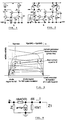
- Fig. 1 shows a basic circuit of a current comparator circuit realized according to the present invention using exclusively n-channel devices.
- the primary function of the circuit is that of discriminating which of the two currents I1 and I2 is the highest.
- the two currents I1 and I2 are, respectively, forced through the two branches of the circuit where one branch comprises the transistor M1 and the other branch comprises the transistor M2.
- the two complementary output nodes, designated "out” and 2 respectively, alternatively assume a "high” voltage level and a "low” voltage level in function of the result of a comparison between the two currents I1 and I2.
- a fundamental aspect of the circuit of this invention is the use of a stage that is substantially of the "source-follower" type, which in the example shown in Fig. 5, is constituted by the third transistor M4 and by the respective bias current generator Ibias.
- one or the other of the two transistors M1 and M2 is configured as a diode by the state assumed by the transistor M4. In this way a current mirror is realized in practice, which actually "copies" the lowest of the two currents on the branch through which the highest current is being forced.
- Equation 1 highlights that for a certain drain current, the voltage Vgs must become very high when the voltage Vds approaches zero, while according to equation 2, the voltage Vds may assume whichever value for a fixed value of the Vgs voltage.
- the circuit is capable of exploiting these correlations for attaining in practice only two stable conditions, as shown by way of an example by the following relationships:
- the transistor M2 is practically diode-configured, thus causing the mirroring of the current I2 on the transistor M1 (in fact, during this phase the transistor M4 behaves as source-follower).
- the transistor M1 that is diode-configured by the transistor M4 and therefore it causes the mirroring of the current I1 on the transistor M2.
- FIG. 3 A complete evolution of the output DC characteristic of MOS transistors is shown in Fig. 3.
- the transistor M2 is originally configured as a diode and the voltage (Vout) on the node "out" evolves through the points 1, 2 and 3 indicated on the characteristics up to a point where the increasing of the current I1 brings the system to the operating point indicated by the letter a .
- the output voltage Vout on the node "out” will also increase evolving along the linear region of the output characteristics of the MOS transistor M7, accompanied by a further increase of the Vgs voltage.
- the potential of the complementary node 2 of the circuit evolves in an exactly opposite way, only the end voltages reached by the nodes "out" and 2 are slightly different. More exactly, the final voltage on node 2 will be given by the Vgs voltage of the transistor M2 plus the Vgs M2 voltage.
- the impedance Z1 of the output node "out” may be calculated, according to the equations 3 and 4 below, where the resistance r ds4 represents the drain-source resistance of the transistor M4 and therefore the feedback resistance of the transistor M1 which is a function of the voltage V2 of node 2.
- the transistor M4 when I1 ⁇ I2, the transistor M4 exhibits a very low r ds4 by virtue of its high Vgs. Conversely, the resistance r ds6 is low because the transistor M6 is functioning in a linear region.
- the drain-source resistance of all the MOS transistors involved is high and the speed of the circuit is controlled by the time constant ⁇ 2 because it becomes more and more independent of the Vgs of the transistor M4.
- the time constant ⁇ 2 assumes a constant value when the voltage V1 reaches the saturation value V dsat , as shown in Fig. 3 by the intersection point a .
- This expression contains a pole and a zero.
- the zero's frequency is rather low whereas the frequency of the pole is by two to three decades higher.
- the drain-source resistance of the transistor M4 maintains an important role. It controls the transfer function and is dependent on the voltage Vgs M4 . In other words, it is strongly nonlinear.
- Scope of a first simulation is that of testing equation 9 and particularly the effect of the parameter r ds4 on the speed and precision characteristics.
- Fig. 5 shows the transient diagrams for different values of the bias current "ibi".
- the rise-time remains within the interval of 30 to 40 nanoseconds (n).
- the maximum speed of 30n is obtained with the highest value of "ibi".
- the circuit has an intrinsic slew-rate determined by the capacitance of the output node "out" which does not appear in equation 9 and depends from the input ramp.
- the separation between the different curves is of about 100ns, in agreement with the theoretical value of 125 ⁇ s. This value is obtained by employing a ramp generator having a gradient of 4A/s and the current value of "ibi".
- Fig. 6 depicts the diagrams of the trailing front transient analysis.
- the delays in this case are more pronounced because the current is lower than during the leading front transient. It is however important to note that no problem of switching-back is manifested. Such a problem is practically inexistent because even if the current I1 became zero, the output voltage can assume only the same null value.
- the impulse rise-time was reduced to 5ns with drain voltages of the transistor M6 and M8 reduced to 2V in order to simulate the worst case.
- the parasitic capacitance C2 has an important role in determining the response characteristics of the circuit. This capacitance does not have a major effect during switching, because the value of the drain source r ds4 resistance is so high that the output node "out" is completely isolated from the capacitance C3.
- the evolution of the voltage Vout of the "out” node is controlled by the slew-rate characteristics and not by the time constant. For this reason, the effect on the capacitance C3 should manifest itself during the first part of the transient, before the turning point of the switching.
- the capacitive load on the node 2 slows-down the functioning of the circuit.
- the load capacitance of the node 2 slows down the evolution of the voltage on the node 2, according to equation 8, and, in the limit, the above mentioned compensation becomes insufficient leading to the consequent switching off of the transistor M4.
- the circuit requires a period of time relatively long for regaining its functionality.
- bias current ibi the lower is the likelihood that such an effect has to take place, ensuring a conduction state of all the circuit transistors.
- An alternative way of compensating such a current injection could be that of adding a capacitance of an appropriate value between the nodes 2 and 3 of the circuit.
- Fig. 9 shows an embodiment of the circuit with p-channel MOS transistors rather than with n-channel transistors as in the example analyzed.
- Fig. 10 shows an alternative embodiment of the circuit of the invention with cascoded p-channel transistors.
- cascoded p-channel transistors Of course, a similar complementary scheme would employ cascoded n-channel transistors.
- FIG. 11 shows a configuration of the circuit of the invention according to a complementary architecture, using both p-channel and n-channel transistors.
Landscapes
- Engineering & Computer Science (AREA)
- Physics & Mathematics (AREA)
- Microelectronics & Electronic Packaging (AREA)
- Nonlinear Science (AREA)
- Electromagnetism (AREA)
- General Physics & Mathematics (AREA)
- Radar, Positioning & Navigation (AREA)
- Automation & Control Theory (AREA)
- Power Engineering (AREA)
- Amplifiers (AREA)
- Manipulation Of Pulses (AREA)
Abstract

Description
- The present invention relates to integrated circuits of signal processing and in particular to current comparators.
- Current comparator circuits are ubiquitous components of many analog systems including data converters and similar front-end signal processing applications. The smallest size of devices, high speed and low consumption constitute the basic requisites of any new project of this type.
- The articles:
- "Novel approach to high speed CMOS current comparators", by H. Träff, Electronics Letters, January 30, 1992, Vol. 28, No. 3;
- "Fast CMOS multilevel current comparator", by H. Gustat, Electronics Letters, April 1, 1993, Vol. 29, No. 7; and
- "High performance CMOS current comparator", by A.T.K. Tang and C. Toumazou, Electronics Letters, January 6, 1994, Vol. 30, No. 1,
- The comparison between two currents is made by forcing the currents to be compared through the two branches of a differential (unbalance) stage circuit so as to be able to discriminate the highest (or lowest) input current by monitoring the respective voltage levels of two nodes, respectively of one and the other branch of the unbalance circuit. Usually, while one of the nodes swings to voltage close to the supply voltage, the other node drops down to a potential close to the common ground potential of the circuit. A dedicated buffer stage or several stages in cascode provide a logic signal that is representative of the result of the comparison between the two input currents, forced through the respective branches of the comparator circuit.
- Forcing the currents to be compared through the respective branches of the comparator circuit implies an absorption of these currents from a supply rail and therefore an attendant consumption which will be more or less high depending on the level of the input currents to be compared.
- In many instances, the absorption and therefore the consumption depends substantially from the level of the highest current being compared which may indeed be a preestablished reference current with which to compare a certain current signal.
- It has now been found and constitutes the object of the present invention, a method and a respective circuit arrangement capable of markedly limiting the absorption of current by a current comparator circuit. The invention consists in limiting the absorption of current through the branch of the comparator circuit along which is forced the highest current to the value of the lowest current which is in turn forced through the other branch of the comparator circuit. This condition is obtained without interfering in any way on other characteristics of switching speed and sensitivity of the comparator circuit.
- This twofold function of the circuit: that is of comparing and at the same time limiting the current absorption, is implemented with an extremely simple circuit that requires an exceptionally reduced number of components, basically only three transistors, thus offering advantages also in terms of the overall economy of integration.
- Fundamentally the invention consists in discriminating the level of two currents while limiting the current in the branch of the unbalanced circuit through which is being forced the highest of the two currents to the value of the other (lowest) current which flows in the other branch of the unbalanced circuit. In practice, the circuit of the invention is able to accomplish the required comparison through operating at a current level that is limited to the value of the lowest current, without requiring the use of any switch or other digitally controlled device.
- The output or sensing node of the branch through which is forced the "lowest" current assumes a relatively "low" potential, whereas the other output or sensing node, that is the "output" node of the branch through which is forced the "highest" current assumes a relatively "high" potential. In other words, the logic configuration provided by the comparator circuit is coherent with the relative level of the compared currents.
- An important aspect of the circuit of this invention is the fact that it is composed of a particularly reduced number of components, if compared to the number of components required for realizing known current comparator circuits with similar performances.
- The circuit of the invention can be designed in CMOS technology by either employing exclusively p-channel devices or by employing cascoded n-channel or p-channel devices, or in a complementary form employing devices of both types of conductivity.
- Essentially, the circuit of the invention uses a source-follower stage that can, for example, be constituted of by a single MOS transistor, whose state or electrical behavior is determined by the logic configuration assumed by the two complementary output nodes of the respective branches of the current comparator circuit. Such a stage or device is capable of assuming an operating state that effectively limits the current in the branch of the circuit through which the highest current is being forced to a value equivalent to the value of the lowest current that is being forced through the other branch of the comparator circuit.
- In the case of a stage realized with a single MOS transistor, it is advantageously exploited the capacity of such device of assuming different operating states (in a so-called linear zone or in a saturation zone) in function of the difference of potential of the two (complementary) output nodes of the comparator circuit. This mechanism eventually produces a configuration of a current mirror circuit that mirrors the lowest current on the branch through which the highest current is being forced, while ensuring a stable switching of the comparator circuit.
- The various aspects, relative advantages and operating features of the circuit of this invention will be even more easily understood through the following description of some important embodiments and by referring to the enclosed figures, wherein:
- Figure 1 is a basic scheme of a current comparator circuit realized according to the present invention;
- Figure 2 shows an alternative embodiment of the comparator circuit of the present invention;
- Figure 3 shows the functioning diagrams of the basic circuit of the invention;
- Figure 4 shows an equivalent electric scheme for small signals of the pair of transistors M4 and M1 of the basic circuit of this invention;
- Figure 5 shows diagrams of the response characteristic for different current levels obtained by simulation;
- Figure 6 shows the trailing fronts for different current levels obtained by simulation;
- Figure 7 shows the switchings rise-time;
- Figure 8 shows the effect of the capacitance C3;
- Figure 9 depicts a circuit of the invention realized with p-channel devices;
- Figure 10 is a circuit of the invention realized with cascoded p-channel devices;
- Figure 11 shows an embodiment of the circuit of the invention according to a complementary architecture.
- Fig. 1 shows a basic circuit of a current comparator circuit realized according to the present invention using exclusively n-channel devices.
- The primary function of the circuit is that of discriminating which of the two currents I1 and I2 is the highest. The two currents I1 and I2 are, respectively, forced through the two branches of the circuit where one branch comprises the transistor M1 and the other branch comprises the transistor M2. The two complementary output nodes, designated "out" and 2, respectively, alternatively assume a "high" voltage level and a "low" voltage level in function of the result of a comparison between the two currents I1 and I2.
- A fundamental aspect of the circuit of this invention is the use of a stage that is substantially of the "source-follower" type, which in the example shown in Fig. 5, is constituted by the third transistor M4 and by the respective bias current generator Ibias.
- In practice, depending on the result of the comparison between the two currents I1 and I2 and of the consequent eventual circuit switching, one or the other of the two transistors M1 and M2 is configured as a diode by the state assumed by the transistor M4. In this way a current mirror is realized in practice, which actually "copies" the lowest of the two currents on the branch through which the highest current is being forced.
- In the case of the circuit shown in Fig. 1, this behavior is obtained by exploiting the output characteristics of the MOS transistor M4, in a linear zone and in a saturation zone, respectively.
- It is well known that the output current of an MOS device follows the following physical laws:


- By fixing the drain current value, it is possible to verify how the respective voltages Vgs and Vds behave. In a linear zone of the operating characteristics, these voltages have a mutual influence on each other whereas in a saturation zone of the operating characteristics, the current is controlled by the voltage Vgs and only secondarily by the voltage Vds.
Equation 1 highlights that for a certain drain current, the voltage Vgs must become very high when the voltage Vds approaches zero, while according toequation 2, the voltage Vds may assume whichever value for a fixed value of the Vgs voltage. - By referring to the basic scheme of Fig. 1, the circuit is capable of exploiting these correlations for attaining in practice only two stable conditions, as shown by way of an example by the following relationships:
- a) I1 > I2 V(out) ≅ 5V V(2) ≅ 0V
- b) I1 < I2 V(out) ≅ 0V V(2) ≅ 5V
- c) I1 = I2 unstable.
- During a phase a) the transistor M2 is practically diode-configured, thus causing the mirroring of the current I2 on the transistor M1 (in fact, during this phase the transistor M4 behaves as source-follower). During a phase b) it is the transistor M1 that is diode-configured by the transistor M4 and therefore it causes the mirroring of the current I1 on the transistor M2.
- In order to enable a complete scan of the working characteristics of the basic circuit of the invention, a test circuit whose electric scheme is depicted in Fig. 2 has been formulated.
- A complete evolution of the output DC characteristic of MOS transistors is shown in Fig. 3. By starting a test run of the circuit of Fig. 2 from a condition whereby I1<I2, the transistor M2 is originally configured as a diode and the voltage (Vout) on the node "out" evolves through the
points - By assuming that the two MOS transistors M1 and M2 are of the same size, the operating point a will be reached when the current I1 equals the current I2 (I1=I2). In this condition, the voltage Vgs of the transistors M1 and M2 cannot increase further.
- As a consequence, the output voltage (Vout) must shift along the output characteristic of the transistor M1 in the order to verify the condition

point 4 for reaching the new point of stability indicated by the letter b. - If the current I1 continues to increase, the output voltage Vout on the node "out" will also increase evolving along the linear region of the output characteristics of the MOS transistor M7, accompanied by a further increase of the Vgs voltage.
- The potential of the
complementary node 2 of the circuit evolves in an exactly opposite way, only the end voltages reached by the nodes "out" and 2 are slightly different. More exactly, the final voltage onnode 2 will be given by the Vgs voltage of the transistor M2 plus the VgsM2 voltage. - It is possible to evaluate the transfer function, that is the relationship between the input current I1 and the output voltage on the
node 2, of the circuit of Fig. 2, through an analysis for small signals, bearing in mind that this simplification does not exactly reflect the real operating conditions of the circuit. The analysis anyway capable of identifying the necessary elements for trimming the circuit toward the required speed and resolution characteristics. - Firstly, it is important to establish the impedance Z1 of the output node "out". The equivalent circuit for small signals of the transistor pair M4 and M1, is shown in Fig. 4, wherein Z represents the complex impedance between the common gate of transistors M1 and M2 and ground.
- Once a given input current i through the drain d of the transistor M4 is fixed, by calculating the derivative of the relation between said current i and the drain voltage Vd4, the impedance Z1 of the output node "out" may be calculated, according to the
equations node 2.
- A simpler model for the impedance Z may be obtained by closely observing the diagram of Fig. 2. The capacitance C3 can be considered representative of the impedance Z, consequently

equation 4, we obtain the following explicit solution for Z1:
- Obviously, a more significant mathematical relation is the link between the input current I1 and the voltage V2 of the
circuit node 2. Indeed, this relation links the value of the resistance rds4 with I1 through the voltage V2. By referring to the circuit schemes of Fig. 2 and Fig. 4, the following relations may be derived.
- Observing the diagram of Fig. 2, a more significant expression for Z2 can be written as in the following equation 7:

- Substituting equation 7 into equation 6, we obtain the following expression for V2/I1:

node 2 of the circuits depicted in Figures 1 and 2. -
Equation 8 shows the existence of two poles, the dominant pole has a time constant given by:
- A second pole is determined by the parasitic capacitance C3, with a time constant given by:

- It is important to consider that both these time constants are strongly dependent on the bias conditions of the circuit, because the drain-source impedance of MOS transistors varies drastically during the circuit switching transients.
- For instance, when I1<I2, the transistor M4 exhibits a very low rds4 by virtue of its high Vgs. Conversely, the resistance rds6 is low because the transistor M6 is functioning in a linear region.
- During a transition I1=I2, the drain-source resistance of all the MOS transistors involved is high and the speed of the circuit is controlled by the time constant τ2 because it becomes more and more independent of the Vgs of the transistor M4. The time constant τ2 assumes a constant value when the voltage V1 reaches the saturation value Vdsat, as shown in Fig. 3 by the intersection point a.
- Another significant verification is the evolution of the output node "out".
- The equation that ties I1 with V1 is
equation 5, this equation is rewritten below as equation 9.
- This expression contains a pole and a zero. The zero's frequency is rather low whereas the frequency of the pole is by two to three decades higher. The drain-source resistance of the transistor M4 maintains an important role. It controls the transfer function and is dependent on the voltage VgsM4. In other words, it is strongly nonlinear.
- The following simulations refer to the test circuit scheme of Fig. 2. The following table shows the parameters used for this evaluation:

- Scope of a first simulation is that of testing equation 9 and particularly the effect of the parameter rds4 on the speed and precision characteristics.
- Fig. 5 shows the transient diagrams for different values of the bias current "ibi". The rise-time remains within the interval of 30 to 40 nanoseconds (n). Of course, the maximum speed of 30n is obtained with the highest value of "ibi".
- The circuit has an intrinsic slew-rate determined by the capacitance of the output node "out" which does not appear in equation 9 and depends from the input ramp.
- The separation between the different curves is of about 100ns, in agreement with the theoretical value of 125µs. This value is obtained by employing a ramp generator having a gradient of 4A/s and the current value of "ibi".
- Fig. 6 depicts the diagrams of the trailing front transient analysis. The delays in this case are more pronounced because the current is lower than during the leading front transient. It is however important to note that no problem of switching-back is manifested. Such a problem is practically inexistent because even if the current I1 became zero, the output voltage can assume only the same null value.
- Of course, there exists a limit for the response speed of the circuit, at which the circuit becomes incapable of discriminating the currents. With the aim of determining such a limit, a simulation was carried out according to the following parameters and conditions:

- The impulse rise-time was reduced to 5ns with drain voltages of the transistor M6 and M8 reduced to 2V in order to simulate the worst case.
- The result of this simulation is shown in the diagram of Fig. 7 wherefrom it can be observed that the maximum transient speed for a current variation ΔIM9=40µA is 16ns.
- As demonstrated by the AC analysis, the parasitic capacitance C2 has an important role in determining the response characteristics of the circuit. This capacitance does not have a major effect during switching, because the value of the drain source rds4 resistance is so high that the output node "out" is completely isolated from the capacitance C3. The evolution of the voltage Vout of the "out" node is controlled by the slew-rate characteristics and not by the time constant. For this reason, the effect on the capacitance C3 should manifest itself during the first part of the transient, before the turning point of the switching.
- This is confirmed by the simulation results shown in Fig. 8. The effect of the capacitance C3 can be considered as a delay factor in switching, because the voltage on the
node 3 cannot any longer follow the ramp speed for ever increasing values of the capacitance C3. A further simple and intuitive interpretation can be made by considering the overall current balance on the output node "out". - The simulations demonstrate that the characteristics of the leading transient tend to get closer to each other for relatively high values of C3; the limit being given by missing the transition for C3 tending to infinity.
- The capacitive load on the
node 2 slows-down the functioning of the circuit. - A lower "ibi", current has the effect of impelling the transistors M4, M1 and M2 toward an OFF-state. Indeed, the coupling capacitance between the drain and the gate of M1 injects current into the
node 3 and switches off the transistor M4, thus precluding the mirroring of the current of M2 on M1. The following equations define the OFF-state condition for the transistor M4:
- Due to the fact that the switching of the complementary nodes "out" and 2, in the absence of a capacitance CP2, have similar time constants, the two drain-gate capacitances of the transistors M2 and M1 share the charge injected into
node 3 thus preventing the switching off of the transistor M4. - In conclusion, the load capacitance of the node 2 (CP2) slows down the evolution of the voltage on the
node 2, according toequation 8, and, in the limit, the above mentioned compensation becomes insufficient leading to the consequent switching off of the transistor M4. In this case, the circuit requires a period of time relatively long for regaining its functionality. - Of course, the higher is the bias current ibi, the lower is the likelihood that such an effect has to take place, ensuring a conduction state of all the circuit transistors. An alternative way of compensating such a current injection could be that of adding a capacitance of an appropriate value between the
nodes - Of course, the circuit of the invention can be realized in different ways. Fig. 9 shows an embodiment of the circuit with p-channel MOS transistors rather than with n-channel transistors as in the example analyzed.
- Fig. 10 shows an alternative embodiment of the circuit of the invention with cascoded p-channel transistors. Of course, a similar complementary scheme would employ cascoded n-channel transistors.
- Finally Fig. 11 shows a configuration of the circuit of the invention according to a complementary architecture, using both p-channel and n-channel transistors.
Claims (8)
- Current comparator circuit capable of producing a logic configuration of two complementary nodes, respectively of a first and of a second branch of the circuit, in function of the comparison between a first current forced through said first branch and a second current forced through said second branch of the circuit, characterized in that it comprisesmeans responsive to the logic configuration of said complementary nodes and assuming a state capable of limiting the current in the branch through which is forced the highest current to the value of the current forced through the other branch of the circuit.
- The current comparator circuit as defined in claim 1, characterized in that said means consist of at least a transistor having a control terminal coupled to one of said nodes and current terminals coupled to the other of said nodes and to a common control node, respectively, of a pair of transistors of said first and of said second branch, respectively, of the circuit and a bias current generator connected between a common supply node of the circuit and said common control node.
- The current comparator circuit according to claim 2, characterized in that said means comprise a pair of transistors cross-coupled to the two circuit branches.
- The current comparator circuit according to any of the claims 1 and 2, characterized in that it is realized with p-channel MOS transistors.
- The current comparator circuit according to any of the claims 1 and 2, characterized in that it is realized with n-channel MOS transistors.
- The current comparator circuit according to any of the claims 1 and 2, characterized in that it is realized with cascoded p-channel MOS transistors.
- The current comparator circuit according to any of the claims 1 and 2, characterized in that it is realized with cascoded n-channel MOS transistors.
- A method for limiting the absorption of current of a current comparator circuit capable of producing a logic configuration of two complementary nodes of a first branch and of a second branch, respectively, of the circuit in function of the comparison between a first current forced through said first branch and a second current forced through said second branch, characterized in that it comprisesdiscriminating the lowest between said two currents;mirroring said discriminated lowest current on the circuit branch into which the highest current is being forced.
Priority Applications (3)
| Application Number | Priority Date | Filing Date | Title |
|---|---|---|---|
| EP95830420A EP0768760B1 (en) | 1995-10-09 | 1995-10-09 | Current comparator |
| DE69507033T DE69507033T2 (en) | 1995-10-09 | 1995-10-09 | Current comparator |
| US08/728,396 US5770954A (en) | 1995-10-09 | 1996-10-09 | Current comparator with intrinsic limitation of absorption to the lowest current level |
Applications Claiming Priority (1)
| Application Number | Priority Date | Filing Date | Title |
|---|---|---|---|
| EP95830420A EP0768760B1 (en) | 1995-10-09 | 1995-10-09 | Current comparator |
Publications (2)
| Publication Number | Publication Date |
|---|---|
| EP0768760A1 true EP0768760A1 (en) | 1997-04-16 |
| EP0768760B1 EP0768760B1 (en) | 1998-12-30 |
Family
ID=8222028
Family Applications (1)
| Application Number | Title | Priority Date | Filing Date |
|---|---|---|---|
| EP95830420A Expired - Lifetime EP0768760B1 (en) | 1995-10-09 | 1995-10-09 | Current comparator |
Country Status (3)
| Country | Link |
|---|---|
| US (1) | US5770954A (en) |
| EP (1) | EP0768760B1 (en) |
| DE (1) | DE69507033T2 (en) |
Cited By (3)
| Publication number | Priority date | Publication date | Assignee | Title |
|---|---|---|---|---|
| EP0932094A1 (en) * | 1998-01-26 | 1999-07-28 | Alcatel | Low-noise impulse current generation apparatus |
| WO2007118540A1 (en) * | 2006-04-07 | 2007-10-25 | Atmel Germany Gmbh | Fast cmos current mirror |
| CN106406419A (en) * | 2016-10-11 | 2017-02-15 | 北京航空航天大学 | Low-sensitivity low-voltage current mirror |
Families Citing this family (4)
| Publication number | Priority date | Publication date | Assignee | Title |
|---|---|---|---|---|
| JP3716574B2 (en) * | 1997-10-07 | 2005-11-16 | 株式会社ニコン | Method of predicting durability of optical member against excimer laser irradiation and method of selecting quartz glass optical member |
| US10186942B2 (en) * | 2015-01-14 | 2019-01-22 | Dialog Semiconductor (Uk) Limited | Methods and apparatus for discharging a node of an electrical circuit |
| US12040785B2 (en) * | 2021-09-24 | 2024-07-16 | Qualcomm Incorporated | Robust transistor circuitry |
| US11977403B2 (en) * | 2022-01-13 | 2024-05-07 | Texas Instruments Incorporated | Multi-segment FET gate enhancement detection |
Citations (5)
| Publication number | Priority date | Publication date | Assignee | Title |
|---|---|---|---|---|
| GB2058504A (en) * | 1979-09-18 | 1981-04-08 | Rca Corp | Amlifiers with non-linear component current amplifiers |
| DE3035471A1 (en) * | 1979-09-21 | 1981-04-09 | Pioneer Electronic Corp., Tokyo | AMPLIFIER CIRCUIT |
| EP0349954A2 (en) * | 1988-07-05 | 1990-01-10 | Motorola, Inc. | Voltage clamped differential to single ended converter circuit |
| US5136184A (en) * | 1991-05-24 | 1992-08-04 | Analog Devices, Incorporated | Fast-acting current comparator |
| US5142696A (en) * | 1991-04-16 | 1992-08-25 | Motorola, Inc. | Current mirror having increased output swing |
Family Cites Families (5)
| Publication number | Priority date | Publication date | Assignee | Title |
|---|---|---|---|---|
| US4069460A (en) * | 1976-09-30 | 1978-01-17 | National Semiconductor Corporation | Current comparator circuit |
| US4554468A (en) * | 1983-07-01 | 1985-11-19 | Motorola, Inc. | Latching comparator with hysteresis |
| JP2882163B2 (en) * | 1992-02-26 | 1999-04-12 | 日本電気株式会社 | Comparator |
| TW239190B (en) * | 1993-04-30 | 1995-01-21 | Philips Electronics Nv | |
| US5349286A (en) * | 1993-06-18 | 1994-09-20 | Texas Instruments Incorporated | Compensation for low gain bipolar transistors in voltage and current reference circuits |
-
1995
- 1995-10-09 EP EP95830420A patent/EP0768760B1/en not_active Expired - Lifetime
- 1995-10-09 DE DE69507033T patent/DE69507033T2/en not_active Expired - Fee Related
-
1996
- 1996-10-09 US US08/728,396 patent/US5770954A/en not_active Expired - Lifetime
Patent Citations (5)
| Publication number | Priority date | Publication date | Assignee | Title |
|---|---|---|---|---|
| GB2058504A (en) * | 1979-09-18 | 1981-04-08 | Rca Corp | Amlifiers with non-linear component current amplifiers |
| DE3035471A1 (en) * | 1979-09-21 | 1981-04-09 | Pioneer Electronic Corp., Tokyo | AMPLIFIER CIRCUIT |
| EP0349954A2 (en) * | 1988-07-05 | 1990-01-10 | Motorola, Inc. | Voltage clamped differential to single ended converter circuit |
| US5142696A (en) * | 1991-04-16 | 1992-08-25 | Motorola, Inc. | Current mirror having increased output swing |
| US5136184A (en) * | 1991-05-24 | 1992-08-04 | Analog Devices, Incorporated | Fast-acting current comparator |
Cited By (6)
| Publication number | Priority date | Publication date | Assignee | Title |
|---|---|---|---|---|
| EP0932094A1 (en) * | 1998-01-26 | 1999-07-28 | Alcatel | Low-noise impulse current generation apparatus |
| FR2774232A1 (en) * | 1998-01-26 | 1999-07-30 | Alsthom Cge Alcatel | DEVICE FOR GENERATING LOW NOISE CURRENT PULSES, PHASE COMPARATOR, SYNTHESIZER AND USE THEREOF |
| WO2007118540A1 (en) * | 2006-04-07 | 2007-10-25 | Atmel Germany Gmbh | Fast cmos current mirror |
| US7466202B2 (en) | 2006-04-07 | 2008-12-16 | Atmel Germany Gmbh | High-speed CMOS current mirror |
| CN106406419A (en) * | 2016-10-11 | 2017-02-15 | 北京航空航天大学 | Low-sensitivity low-voltage current mirror |
| CN106406419B (en) * | 2016-10-11 | 2018-02-16 | 北京航空航天大学 | A kind of low sensitivity low-voltage current mirror |
Also Published As
| Publication number | Publication date |
|---|---|
| DE69507033D1 (en) | 1999-02-11 |
| DE69507033T2 (en) | 1999-05-12 |
| EP0768760B1 (en) | 1998-12-30 |
| US5770954A (en) | 1998-06-23 |
Similar Documents
| Publication | Publication Date | Title |
|---|---|---|
| KR100304813B1 (en) | Negative Resistance Circuit and Schmitt Trigger Circuit Using It | |
| KR960005360B1 (en) | Circuit arrangement for processing sampled analogue electrical signal | |
| US6014042A (en) | Phase detector using switched capacitors | |
| US5909127A (en) | Circuits with dynamically biased active loads | |
| US5289054A (en) | Fast electronic comparator | |
| EP0138823B1 (en) | A current source circuit having reduced error | |
| US4410813A (en) | High speed CMOS comparator circuit | |
| KR900000993B1 (en) | The comparator circuit with the improved output characteristics | |
| EP0768760B1 (en) | Current comparator | |
| US4751405A (en) | Externally programmable, process and temperature insensitive threshold receiver circuit | |
| EP0872850B1 (en) | High-precision analog reading circuit for memory arrays, in particular flash analog memory arrays | |
| KR100574968B1 (en) | The OP-Amplifier with offset cancellation circuit | |
| WO2000005814A1 (en) | Differential comparator with stable switching threshold | |
| US5714894A (en) | Current comparator arrangement | |
| US5583425A (en) | Voltage comparator with controlled output current proportional to difference voltage | |
| US4818897A (en) | Fast one way amplifier stage | |
| US6501303B1 (en) | Semiconductor integrated circuit | |
| GB2283626A (en) | Driver for MOS sampling switch | |
| US4871931A (en) | Logic circuit resistant to errors due to supply fluctuations | |
| US6538496B1 (en) | Low voltage, high impedance current mirrors | |
| US4438388A (en) | Single stage operational amplifier voltage reference | |
| US5910744A (en) | Variable delaying circuit having a nearly linear delay characteristic | |
| CN114039560B (en) | Operational amplifier and output stage circuit thereof | |
| US6888401B1 (en) | Current mode current sense circuits and methods | |
| KR0121102B1 (en) | Constant voltage device |
Legal Events
| Date | Code | Title | Description |
|---|---|---|---|
| PUAI | Public reference made under article 153(3) epc to a published international application that has entered the european phase |
Free format text: ORIGINAL CODE: 0009012 |
|
| AK | Designated contracting states |
Kind code of ref document: A1 Designated state(s): DE FR GB IT |
|
| 17P | Request for examination filed |
Effective date: 19970721 |
|
| 17Q | First examination report despatched |
Effective date: 19970826 |
|
| GRAG | Despatch of communication of intention to grant |
Free format text: ORIGINAL CODE: EPIDOS AGRA |
|
| GRAG | Despatch of communication of intention to grant |
Free format text: ORIGINAL CODE: EPIDOS AGRA |
|
| GRAH | Despatch of communication of intention to grant a patent |
Free format text: ORIGINAL CODE: EPIDOS IGRA |
|
| RAP3 | Party data changed (applicant data changed or rights of an application transferred) |
Owner name: STMICROELECTRONICS S.R.L. |
|
| GRAH | Despatch of communication of intention to grant a patent |
Free format text: ORIGINAL CODE: EPIDOS IGRA |
|
| GRAA | (expected) grant |
Free format text: ORIGINAL CODE: 0009210 |
|
| AK | Designated contracting states |
Kind code of ref document: B1 Designated state(s): DE FR GB IT |
|
| REF | Corresponds to: |
Ref document number: 69507033 Country of ref document: DE Date of ref document: 19990211 |
|
| ITF | It: translation for a ep patent filed | ||
| ET | Fr: translation filed | ||
| PLBE | No opposition filed within time limit |
Free format text: ORIGINAL CODE: 0009261 |
|
| STAA | Information on the status of an ep patent application or granted ep patent |
Free format text: STATUS: NO OPPOSITION FILED WITHIN TIME LIMIT |
|
| 26N | No opposition filed | ||
| REG | Reference to a national code |
Ref country code: GB Ref legal event code: IF02 |
|
| PGFP | Annual fee paid to national office [announced via postgrant information from national office to epo] |
Ref country code: DE Payment date: 20041007 Year of fee payment: 10 |
|
| PG25 | Lapsed in a contracting state [announced via postgrant information from national office to epo] |
Ref country code: IT Free format text: LAPSE BECAUSE OF NON-PAYMENT OF DUE FEES;WARNING: LAPSES OF ITALIAN PATENTS WITH EFFECTIVE DATE BEFORE 2007 MAY HAVE OCCURRED AT ANY TIME BEFORE 2007. THE CORRECT EFFECTIVE DATE MAY BE DIFFERENT FROM THE ONE RECORDED. Effective date: 20051009 |
|
| PG25 | Lapsed in a contracting state [announced via postgrant information from national office to epo] |
Ref country code: DE Free format text: LAPSE BECAUSE OF NON-PAYMENT OF DUE FEES Effective date: 20060503 |
|
| PGFP | Annual fee paid to national office [announced via postgrant information from national office to epo] |
Ref country code: GB Payment date: 20130923 Year of fee payment: 19 |
|
| PGFP | Annual fee paid to national office [announced via postgrant information from national office to epo] |
Ref country code: FR Payment date: 20131028 Year of fee payment: 19 |
|
| GBPC | Gb: european patent ceased through non-payment of renewal fee |
Effective date: 20141009 |
|
| PG25 | Lapsed in a contracting state [announced via postgrant information from national office to epo] |
Ref country code: GB Free format text: LAPSE BECAUSE OF NON-PAYMENT OF DUE FEES Effective date: 20141009 |
|
| REG | Reference to a national code |
Ref country code: FR Ref legal event code: ST Effective date: 20150630 |
|
| PG25 | Lapsed in a contracting state [announced via postgrant information from national office to epo] |
Ref country code: FR Free format text: LAPSE BECAUSE OF NON-PAYMENT OF DUE FEES Effective date: 20141031 |