EP0767984B1 - Apparatus for recharging a battery - Google Patents
Apparatus for recharging a battery Download PDFInfo
- Publication number
- EP0767984B1 EP0767984B1 EP96906885A EP96906885A EP0767984B1 EP 0767984 B1 EP0767984 B1 EP 0767984B1 EP 96906885 A EP96906885 A EP 96906885A EP 96906885 A EP96906885 A EP 96906885A EP 0767984 B1 EP0767984 B1 EP 0767984B1
- Authority
- EP
- European Patent Office
- Prior art keywords
- battery
- ferromagnetic body
- electrical
- coil
- recharging
- Prior art date
- Legal status (The legal status is an assumption and is not a legal conclusion. Google has not performed a legal analysis and makes no representation as to the accuracy of the status listed.)
- Expired - Lifetime
Links
Images
Classifications
-
- H—ELECTRICITY
- H01—ELECTRIC ELEMENTS
- H01M—PROCESSES OR MEANS, e.g. BATTERIES, FOR THE DIRECT CONVERSION OF CHEMICAL ENERGY INTO ELECTRICAL ENERGY
- H01M10/00—Secondary cells; Manufacture thereof
- H01M10/42—Methods or arrangements for servicing or maintenance of secondary cells or secondary half-cells
- H01M10/46—Accumulators structurally combined with charging apparatus
-
- H—ELECTRICITY
- H02—GENERATION; CONVERSION OR DISTRIBUTION OF ELECTRIC POWER
- H02J—ELECTRIC POWER NETWORKS; CIRCUIT ARRANGEMENTS OR SYSTEMS FOR SUPPLYING OR DISTRIBUTING ELECTRIC POWER; SYSTEMS FOR STORING ELECTRIC ENERGY
- H02J7/00—Circuit arrangements for charging or discharging batteries or for supplying loads from batteries
- H02J7/90—Regulation of charging or discharging current or voltage
- H02J7/971—Regulation of charging or discharging current or voltage the charge cycle being controlled or terminated in response to non-electric parameters
-
- Y—GENERAL TAGGING OF NEW TECHNOLOGICAL DEVELOPMENTS; GENERAL TAGGING OF CROSS-SECTIONAL TECHNOLOGIES SPANNING OVER SEVERAL SECTIONS OF THE IPC; TECHNICAL SUBJECTS COVERED BY FORMER USPC CROSS-REFERENCE ART COLLECTIONS [XRACs] AND DIGESTS
- Y02—TECHNOLOGIES OR APPLICATIONS FOR MITIGATION OR ADAPTATION AGAINST CLIMATE CHANGE
- Y02E—REDUCTION OF GREENHOUSE GAS [GHG] EMISSIONS, RELATED TO ENERGY GENERATION, TRANSMISSION OR DISTRIBUTION
- Y02E60/00—Enabling technologies; Technologies with a potential or indirect contribution to GHG emissions mitigation
- Y02E60/10—Energy storage using batteries
Definitions
- the invention relates to an apparatus for recharging a battery, comprising a compartment into which the battery can be placed so that its electrical terminals are in contact with a pair of electrodes, said electrodes being connectable to corresponding poles of a controllable source of electrical energy.
- the invention also relates to a method of recharging a battery, in which changes in a given physical parameter are electronically monitored and exploited as an indicator of the accumulated quantity of electrical charge in the battery.
- battery is here intended to refer to either single cells or battery packs, and refers specifically to secondary (i.e. rechargeable) batteries.
- the mechanical strain in a battery is monitored as a function of charging time, whilst simultaneously measuring the quantity of charge supplied to the battery.
- the measured strain at any given time then allows the corresponding charge value to be deduced.
- the electrical voltage and/or current supplied to the battery during charging can, if so desired, be automatically tailored to particular requirements. For example, it is possible to automatically interrupt charging when the battery is 90% charged, or to slow down the charging procedure as charge saturation is approached.
- the inventive apparatus exploits the insight that, when subjected to mechanical stress, a ferromagnetic body demonstrates a change in magnetic permeability ( ⁇ ) as a result of magnetostriction effects. This phenomenon is elucidated in more detail by S. Chikazumi in Physics of Magnetism, John Wiley & Sons (1964); see chapter 8, and particularly section 8.4. If, therefore, the ferromagnetic body is positioned so as to experience a mechanical force as a result of expansion of the battery during charging, then such expansion will lead to a change in the value of ⁇ , which, in turn, can be monitored electrically.
- the electrical means for monitoring ⁇ comprise a coil of conductive material which surrounds at least a portion of the ferromagnetic body and which is connected to an electrical circuit for measuring the self-inductance (L) of the coil, which circuit comprises an electrical oscillator.
- a coil need only comprise a single loop, but a multiple-loop coil is preferable, since it has a larger inductance (assuming other parameters, such as the loop area, to be equal).
- the coil is connected across an AC voltage source, and L is then measured by further incorporating the coil in one leg of a Wheatstone bridge.
- L is then measured by further incorporating the coil in one leg of a Wheatstone bridge.
- the value of ⁇ can be indirectly monitored by measuring the inductance of the second coil (mutual inductance).
- the ferromagnetic body is a closed magnetic circuit, so as to conserve magnetic flux and optimise the sensitivity of induction measurements.
- the body may simply take the form of a ring.
- a further embodiment of the inventive apparatus can be characterised in that these means are embodied to generate an output signal which is dependent on ⁇ , and that this signal serves as an input signal to regulate the controllable source of electrical energy.
- a preferential embodiment of the apparatus according to the invention is characterised in that the ferromagnetic body comprises ferrite material, e.g. MnZn ferrite.
- ferrite material e.g. MnZn ferrite.
- Such materials have a relatively high value of ⁇ (at room temperature), and are commercially available in various forms, including rings.
- Other materials which can be applied in the ferromagnetic body include, for example, NiFe alloys, FeNiCo alloys, Sendust, etc.
- inventive apparatus is also suitable for detecting over-discharging of a battery, since this is also accompanied by internal gas generation and attendant expansion of the battery. In such a scenario, the measured expansion of the battery beyond a certain point can be used as a signal to terminate further discharging.
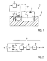
- FIG. 1 shows an apparatus 1 in accordance with the present invention.
- This apparatus 1 comprises a compartment 3 into which a battery 5 can be placed.
- the battery 5 is thus positioned that its terminals are in contact with a pair of electrodes 7, 9.
- These electrodes 7, 9 are in turn connected to a source 11 of electrical energy, which can be switched with the aid of a switch 13.
- a ring 15 of ferromagnetic material which is located between the electrode 7 and a plate 17.
- Elastic means 19 are located between the plate 17 and a wall of the compartment 3. These elastic means 19 are preferably relatively rigid, so that both the ring 15 and the battery 5 are tightly pressed against the plate 17.
- a coil 21 of insulated copper wire is wound around at least part of the ring 15, and is further connected to electrical means 23.
- the coil 21 forms part of an electrical oscillator circuit. This circuit can be used to measure the self-inductance L of the coil 21, which is in turn dependent upon the permeability ⁇ of the ferromagnetic material in the ring 15.
- the switch 13 In order to charge the battery 5, the switch 13 must be closed. As charging approaches completion, the pressure and temperature within the battery 5 tend to rise relatively sharply, causing it to expand slightly. As a result of this expansion, pressure is exercised on the ring 15, leading to a change in the value of ⁇ via magnetostriction.
- a relatively sharp change in L can therefore be employed as an indicator that the charging procedure is approaching its completion.
- the means 23 can be connected to the switch 13 via a signal carrier 25; dependent on the measured value of L, an appropriate signal from the means 23 can then be used to open the switch 13 automatically.
- the coil 21 in Figure 1 is connected across an oscillator 22, in parallel with a pair of series-connected capacitors 24a, 24b which are saddled about ground, thereby forming a resonance circuit.
- the oscillator 22 is further connected to a frequency-to-voltage converter 26, whose output signal is passed to an output 210 via a low-pass filter 28.
- the value of the measured voltage V at the output 210 may be passed to a comparator (not depicted), where it can be compared with a reference voltage value V o .
- V V o
Landscapes
- Engineering & Computer Science (AREA)
- Power Engineering (AREA)
- Manufacturing & Machinery (AREA)
- Chemical & Material Sciences (AREA)
- Chemical Kinetics & Catalysis (AREA)
- Electrochemistry (AREA)
- General Chemical & Material Sciences (AREA)
- Charge And Discharge Circuits For Batteries Or The Like (AREA)
- Secondary Cells (AREA)
Abstract
Description
Claims (6)
- Apparatus for recharging a battery (5), comprising a compartment (3) into which the battery (5) can be placed so that its electrical terminals are in contact with a pair of electrodes (7, 9), said electrodes (7, 9) being connectable to corresponding poles of a controllable source (11) of electrical energy, characterised in that the compartment (3) comprises a ferromagnetic body (15) which is positioned so as to be subjected to mechanical stress in response to mechanical deformation of the battery (5), and that the apparatus comprises electrical means (23) for monitoring the magnetic permeability of the ferromagnetic body (15).
- Apparatus according to Claim 1, characterised in that the electrical means (23) comprise a coil (21) of conductive material which surrounds at least a portion of the ferromagnetic body (15) and which is connected to an electrical circuit for measuring the self-inductance of the coil (21), which circuit comprises an electrical oscillator (22).
- Apparatus according to Claim 1 or 2, characterised in that the electrical means (23) are embodied to generate an output signal which is dependent on the magnetic permeability of the ferromagnetic body (15), and that this signal serves as an input signal to regulate the controllable source (11) of electrical energy.
- Apparatus according any of the Claims 1-3, characterised in that the ferromagnetic body (15) is a closed magnetic circuit.
- Apparatus according to any of the Claims 1-4, characterised in that the ferromagnetic body (15) comprises ferrite material.
- Method of recharging a battery, in which changes in a given physical parameter are electronically monitored and exploited as an indicator of the accumulated quantity of electrical charge in the battery (5), characterised in that the physical quantity is the magnetic permeability of a ferromagnetic body (15), which is monitored by measuring the electrical inductance of a coil (21) surrounding at least a portion of the ferromagnetic body (15), and which is caused to change by magnetostrictive effects arising from mechanical stress of the ferromagnetic body (15) in response to mechanical deformation of the battery (5) during charging.
Priority Applications (1)
| Application Number | Priority Date | Filing Date | Title |
|---|---|---|---|
| EP96906885A EP0767984B1 (en) | 1995-04-28 | 1996-04-10 | Apparatus for recharging a battery |
Applications Claiming Priority (4)
| Application Number | Priority Date | Filing Date | Title |
|---|---|---|---|
| EP95201110 | 1995-04-28 | ||
| EP95201110 | 1995-04-28 | ||
| EP96906885A EP0767984B1 (en) | 1995-04-28 | 1996-04-10 | Apparatus for recharging a battery |
| PCT/IB1996/000293 WO1996034445A1 (en) | 1995-04-28 | 1996-04-10 | Apparatus for recharging a battery |
Publications (2)
| Publication Number | Publication Date |
|---|---|
| EP0767984A1 EP0767984A1 (en) | 1997-04-16 |
| EP0767984B1 true EP0767984B1 (en) | 2000-09-20 |
Family
ID=8220237
Family Applications (1)
| Application Number | Title | Priority Date | Filing Date |
|---|---|---|---|
| EP96906885A Expired - Lifetime EP0767984B1 (en) | 1995-04-28 | 1996-04-10 | Apparatus for recharging a battery |
Country Status (5)
| Country | Link |
|---|---|
| US (1) | US5680029A (en) |
| EP (1) | EP0767984B1 (en) |
| JP (1) | JPH10502767A (en) |
| DE (1) | DE69610388T2 (en) |
| WO (1) | WO1996034445A1 (en) |
Cited By (1)
| Publication number | Priority date | Publication date | Assignee | Title |
|---|---|---|---|---|
| WO2006077519A1 (en) * | 2005-01-20 | 2006-07-27 | Koninklijke Philips Electronics N.V. | Arrangement and method for monitoring pressure within a battery cell |
Families Citing this family (19)
| Publication number | Priority date | Publication date | Assignee | Title |
|---|---|---|---|---|
| CN1256796A (en) * | 1998-03-05 | 2000-06-14 | 皇家菲利浦电子有限公司 | Magnetostrictive stress sensor |
| CN101529276B (en) | 2006-09-08 | 2013-03-20 | 雪佛龙美国公司 | Telemetry device and method for monitoring drilling |
| US7863907B2 (en) * | 2007-02-06 | 2011-01-04 | Chevron U.S.A. Inc. | Temperature and pressure transducer |
| US7810993B2 (en) * | 2007-02-06 | 2010-10-12 | Chevron U.S.A. Inc. | Temperature sensor having a rotational response to the environment |
| US8106791B2 (en) * | 2007-04-13 | 2012-01-31 | Chevron U.S.A. Inc. | System and method for receiving and decoding electromagnetic transmissions within a well |
| DE102007024908A1 (en) * | 2007-05-29 | 2008-12-04 | Siemens Ag | Tunable inductor and use of the device |
| US7841234B2 (en) * | 2007-07-30 | 2010-11-30 | Chevron U.S.A. Inc. | System and method for sensing pressure using an inductive element |
| US7636052B2 (en) | 2007-12-21 | 2009-12-22 | Chevron U.S.A. Inc. | Apparatus and method for monitoring acoustic energy in a borehole |
| US9547104B2 (en) * | 2007-09-04 | 2017-01-17 | Chevron U.S.A. Inc. | Downhole sensor interrogation employing coaxial cable |
| US8353677B2 (en) | 2009-10-05 | 2013-01-15 | Chevron U.S.A. Inc. | System and method for sensing a liquid level |
| US10488286B2 (en) * | 2009-11-30 | 2019-11-26 | Chevron U.S.A. Inc. | System and method for measurement incorporating a crystal oscillator |
| US8575936B2 (en) | 2009-11-30 | 2013-11-05 | Chevron U.S.A. Inc. | Packer fluid and system and method for remote sensing |
| US8560127B2 (en) | 2011-01-13 | 2013-10-15 | Honeywell International Inc. | HVAC control with comfort/economy management |
| KR101817457B1 (en) * | 2014-03-31 | 2018-01-10 | 도요 고무 고교 가부시키가이샤 | Deformation-detecting sensor for sealed secondary battery |
| WO2015151331A1 (en) * | 2014-03-31 | 2015-10-08 | 東洋ゴム工業株式会社 | Deformation-detecting sensor for sealed secondary battery |
| JP6265847B2 (en) * | 2014-06-27 | 2018-01-24 | 東洋ゴム工業株式会社 | Deformation detection sensor for sealed secondary battery, sealed secondary battery, and deformation detection method for sealed secondary battery |
| JP6186339B2 (en) * | 2014-06-27 | 2017-08-23 | 東洋ゴム工業株式会社 | Sealed secondary battery monitoring sensor, sealed secondary battery, and sealed secondary battery monitoring method |
| US10802459B2 (en) | 2015-04-27 | 2020-10-13 | Ademco Inc. | Geo-fencing with advanced intelligent recovery |
| KR102415271B1 (en) | 2017-09-22 | 2022-07-01 | 삼성전자 주식회사 | Method and electronic device for detecting a battery swelling |
Family Cites Families (8)
| Publication number | Priority date | Publication date | Assignee | Title |
|---|---|---|---|---|
| US4371272A (en) * | 1980-08-29 | 1983-02-01 | Aisin Seiki Company, Limited | Thermodetector |
| US4379816A (en) * | 1980-09-22 | 1983-04-12 | General Electric Company | Indicator of full charge for secondary cell or battery thereof |
| US4689544A (en) * | 1985-10-17 | 1987-08-25 | Hughes Aircraft Company | Control of the charging of pressurized gas-metal electrical storage cells |
| JPS63268445A (en) * | 1987-04-24 | 1988-11-07 | Nec Home Electronics Ltd | Quick charging method of nickel-cadmium secondary battery |
| JPH05121103A (en) * | 1991-10-25 | 1993-05-18 | Fujitsu Ltd | Secondary battery charging method |
| JPH05326027A (en) * | 1992-05-22 | 1993-12-10 | Honda Motor Co Ltd | Charge control method for secondary battery |
| US5438249A (en) * | 1993-06-08 | 1995-08-01 | Valence Technology, Inc. | Method of state-of-charge indication by measuring the thickness of a battery |
| US5567541A (en) * | 1995-03-21 | 1996-10-22 | Lockheed Idaho Technologies Company | Method and apparatus for measuring the state of charge in a battery based on volume of battery components |
-
1996
- 1996-04-10 EP EP96906885A patent/EP0767984B1/en not_active Expired - Lifetime
- 1996-04-10 JP JP8532303A patent/JPH10502767A/en not_active Abandoned
- 1996-04-10 WO PCT/IB1996/000293 patent/WO1996034445A1/en not_active Ceased
- 1996-04-10 DE DE69610388T patent/DE69610388T2/en not_active Expired - Fee Related
- 1996-04-26 US US08/639,994 patent/US5680029A/en not_active Expired - Fee Related
Cited By (2)
| Publication number | Priority date | Publication date | Assignee | Title |
|---|---|---|---|---|
| WO2006077519A1 (en) * | 2005-01-20 | 2006-07-27 | Koninklijke Philips Electronics N.V. | Arrangement and method for monitoring pressure within a battery cell |
| CN100533845C (en) * | 2005-01-20 | 2009-08-26 | 皇家飞利浦电子股份有限公司 | Arrangement and method for monitoring pressure within a battery cell |
Also Published As
| Publication number | Publication date |
|---|---|
| DE69610388T2 (en) | 2001-03-29 |
| WO1996034445A1 (en) | 1996-10-31 |
| EP0767984A1 (en) | 1997-04-16 |
| JPH10502767A (en) | 1998-03-10 |
| DE69610388D1 (en) | 2000-10-26 |
| US5680029A (en) | 1997-10-21 |
Similar Documents
| Publication | Publication Date | Title |
|---|---|---|
| EP0767984B1 (en) | Apparatus for recharging a battery | |
| CA2103156C (en) | Quick charger and quick charge method of nickel-cadmium battery | |
| JP5560290B2 (en) | Apparatus and method for monitoring state of charge, LFP battery including battery state of charge sensor | |
| KR102688064B1 (en) | Method for abnormality detection, system for detecting abnormality, and energy storage system | |
| US4684869A (en) | Electronic clinical thermometer | |
| KR101188808B1 (en) | Wireless charging apparatus for mobile | |
| US8797020B2 (en) | Closed-loop fluxgate current sensor | |
| JP2008529213A (en) | Apparatus and method for monitoring pressure in battery cell | |
| US5714868A (en) | Battery pack and charger arrangement which intermittently monitors battery temperature during recharging and a method thereof | |
| JPS5942538B2 (en) | Devices and systems for indicating and controlling the state of charge of secondary batteries | |
| CN105556324B (en) | Method, analytical equipment and measuring system for monitoring battery | |
| EP0767986B1 (en) | Battery recharging apparatus and method | |
| KR102485762B1 (en) | Magneto-mechano-electric generator with magnetic flux concentrator | |
| EP3997465B1 (en) | Sensing apparatus and sensing method | |
| RU202068U1 (en) | HAND-HELD METAL DETECTOR WITH WIRELESS POWER SUPPLY | |
| JP3346821B2 (en) | Charging device | |
| JP3416854B2 (en) | Rechargeable electrical equipment | |
| SU959189A1 (en) | Method of monitoring the state of chemical power source | |
| Gallien et al. | State of charge determination of LiFePO 4 batteries using an external applied magnetic field | |
| TW201607201A (en) | Wireless power transmission device | |
| JPH02121279A (en) | Life evaluation device for sealed lead-acid batteries | |
| SU1669349A1 (en) | Tester of state of storage cell with flat electrodes of lamellar structure and case made nonconductive nonmagnetic material | |
| JPS62123924A (en) | Discrimination circuit of secondary battery | |
| JPH0686473A (en) | Apparatus and method for charging | |
| JPH02152170A (en) | Life judging method for sealed lead-acid battery |
Legal Events
| Date | Code | Title | Description |
|---|---|---|---|
| PUAI | Public reference made under article 153(3) epc to a published international application that has entered the european phase |
Free format text: ORIGINAL CODE: 0009012 |
|
| AK | Designated contracting states |
Kind code of ref document: A1 Designated state(s): DE FR GB |
|
| 17P | Request for examination filed |
Effective date: 19970502 |
|
| 17Q | First examination report despatched |
Effective date: 19981229 |
|
| GRAG | Despatch of communication of intention to grant |
Free format text: ORIGINAL CODE: EPIDOS AGRA |
|
| GRAG | Despatch of communication of intention to grant |
Free format text: ORIGINAL CODE: EPIDOS AGRA |
|
| GRAH | Despatch of communication of intention to grant a patent |
Free format text: ORIGINAL CODE: EPIDOS IGRA |
|
| GRAH | Despatch of communication of intention to grant a patent |
Free format text: ORIGINAL CODE: EPIDOS IGRA |
|
| GRAA | (expected) grant |
Free format text: ORIGINAL CODE: 0009210 |
|
| AK | Designated contracting states |
Kind code of ref document: B1 Designated state(s): DE FR GB |
|
| REF | Corresponds to: |
Ref document number: 69610388 Country of ref document: DE Date of ref document: 20001026 |
|
| ET | Fr: translation filed | ||
| PLBE | No opposition filed within time limit |
Free format text: ORIGINAL CODE: 0009261 |
|
| STAA | Information on the status of an ep patent application or granted ep patent |
Free format text: STATUS: NO OPPOSITION FILED WITHIN TIME LIMIT |
|
| 26N | No opposition filed | ||
| REG | Reference to a national code |
Ref country code: GB Ref legal event code: IF02 |
|
| REG | Reference to a national code |
Ref country code: GB Ref legal event code: 746 Effective date: 20021025 |
|
| REG | Reference to a national code |
Ref country code: FR Ref legal event code: D6 |
|
| PGFP | Annual fee paid to national office [announced via postgrant information from national office to epo] |
Ref country code: GB Payment date: 20050428 Year of fee payment: 10 Ref country code: FR Payment date: 20050428 Year of fee payment: 10 |
|
| PGFP | Annual fee paid to national office [announced via postgrant information from national office to epo] |
Ref country code: DE Payment date: 20050621 Year of fee payment: 10 |
|
| PG25 | Lapsed in a contracting state [announced via postgrant information from national office to epo] |
Ref country code: GB Free format text: LAPSE BECAUSE OF NON-PAYMENT OF DUE FEES Effective date: 20060410 |
|
| PG25 | Lapsed in a contracting state [announced via postgrant information from national office to epo] |
Ref country code: DE Free format text: LAPSE BECAUSE OF NON-PAYMENT OF DUE FEES Effective date: 20061101 |
|
| GBPC | Gb: european patent ceased through non-payment of renewal fee |
Effective date: 20060410 |
|
| REG | Reference to a national code |
Ref country code: FR Ref legal event code: ST Effective date: 20061230 |
|
| PG25 | Lapsed in a contracting state [announced via postgrant information from national office to epo] |
Ref country code: FR Free format text: LAPSE BECAUSE OF NON-PAYMENT OF DUE FEES Effective date: 20060502 |