EP0767967B1 - High output stationary x-ray target - Google Patents
High output stationary x-ray target Download PDFInfo
- Publication number
- EP0767967B1 EP0767967B1 EP96911083A EP96911083A EP0767967B1 EP 0767967 B1 EP0767967 B1 EP 0767967B1 EP 96911083 A EP96911083 A EP 96911083A EP 96911083 A EP96911083 A EP 96911083A EP 0767967 B1 EP0767967 B1 EP 0767967B1
- Authority
- EP
- European Patent Office
- Prior art keywords
- button
- substrate
- target
- ray
- section
- Prior art date
- Legal status (The legal status is an assumption and is not a legal conclusion. Google has not performed a legal analysis and makes no representation as to the accuracy of the status listed.)
- Expired - Lifetime
Links
- 239000000758 substrate Substances 0.000 claims description 37
- 238000001816 cooling Methods 0.000 claims description 9
- 238000004519 manufacturing process Methods 0.000 claims description 7
- 239000000463 material Substances 0.000 claims description 6
- 238000010894 electron beam technology Methods 0.000 claims description 2
- 239000002826 coolant Substances 0.000 description 12
- 238000013461 design Methods 0.000 description 12
- 238000004458 analytical method Methods 0.000 description 10
- 238000000034 method Methods 0.000 description 7
- 230000008569 process Effects 0.000 description 5
- 239000007788 liquid Substances 0.000 description 4
- 238000005229 chemical vapour deposition Methods 0.000 description 3
- 238000010438 heat treatment Methods 0.000 description 3
- 230000007246 mechanism Effects 0.000 description 3
- 230000009467 reduction Effects 0.000 description 3
- 239000007787 solid Substances 0.000 description 3
- 239000010935 stainless steel Substances 0.000 description 3
- 229910001220 stainless steel Inorganic materials 0.000 description 3
- XLYOFNOQVPJJNP-UHFFFAOYSA-N water Substances O XLYOFNOQVPJJNP-UHFFFAOYSA-N 0.000 description 3
- RYGMFSIKBFXOCR-UHFFFAOYSA-N Copper Chemical compound [Cu] RYGMFSIKBFXOCR-UHFFFAOYSA-N 0.000 description 2
- 238000009835 boiling Methods 0.000 description 2
- 229910052802 copper Inorganic materials 0.000 description 2
- 239000010949 copper Substances 0.000 description 2
- 230000001419 dependent effect Effects 0.000 description 2
- 239000012530 fluid Substances 0.000 description 2
- 238000012360 testing method Methods 0.000 description 2
- 229910045601 alloy Inorganic materials 0.000 description 1
- 239000000956 alloy Substances 0.000 description 1
- 239000010405 anode material Substances 0.000 description 1
- 230000005540 biological transmission Effects 0.000 description 1
- 239000006227 byproduct Substances 0.000 description 1
- 238000004891 communication Methods 0.000 description 1
- 230000001627 detrimental effect Effects 0.000 description 1
- 238000009826 distribution Methods 0.000 description 1
- 230000007774 longterm Effects 0.000 description 1
- 230000000873 masking effect Effects 0.000 description 1
- 238000012986 modification Methods 0.000 description 1
- 230000004048 modification Effects 0.000 description 1
- 230000002028 premature Effects 0.000 description 1
- 230000004044 response Effects 0.000 description 1
- 230000007480 spreading Effects 0.000 description 1
- 238000003892 spreading Methods 0.000 description 1
- 239000013077 target material Substances 0.000 description 1
- 238000012546 transfer Methods 0.000 description 1
Images




Classifications
-
- H—ELECTRICITY
- H01—ELECTRIC ELEMENTS
- H01J—ELECTRIC DISCHARGE TUBES OR DISCHARGE LAMPS
- H01J35/00—X-ray tubes
- H01J35/02—Details
- H01J35/04—Electrodes ; Mutual position thereof; Constructional adaptations therefor
- H01J35/08—Anodes; Anti cathodes
- H01J35/12—Cooling non-rotary anodes
-
- H—ELECTRICITY
- H01—ELECTRIC ELEMENTS
- H01J—ELECTRIC DISCHARGE TUBES OR DISCHARGE LAMPS
- H01J2235/00—X-ray tubes
- H01J2235/12—Cooling
- H01J2235/1204—Cooling of the anode
-
- H—ELECTRICITY
- H01—ELECTRIC ELEMENTS
- H01J—ELECTRIC DISCHARGE TUBES OR DISCHARGE LAMPS
- H01J2235/00—X-ray tubes
- H01J2235/12—Cooling
- H01J2235/1225—Cooling characterised by method
- H01J2235/1262—Circulating fluids
Definitions
- the present invention is directed to liquid cooled anode X-ray generating devices, and in particular to stationary anode X-ray devices having an anode target plate and support structure of unique design to reduce the stresses generated in the high Z anode material and interface stresses produced as a result of the high temperature created during X-ray generation.
- the high Z button of the target is either: (1) bonded directly to a low Z, water cooled substrate, typically copper or some alloy thereof; or (2) bonded to a support at the periphery of the button.
- the button thickness chosen for a particular electron energy is insufficient to completely stop the X-ray producing electrons, and the low Z substrate, whether heat sink or not, serves the secondary purpose of beam stop, thereby preventing the transmission of contaminating electrons. From the physics point of view it is this appropriate combination of high Z button and low Z substrate which enables the production of useful X-rays.
- the present invention provides a stationary X-ray target of unique design according to claim 1, which enhances cooling while minimizing stress in the high Z button and low Z substrate.
- the operating life of the target is thus improved.
- the high Z anode button has a central X-ray producing section which is reduced in diameter, in conjunction with a thin lip which forms the interface with the supporting substrate; preferably the lip has a diameter approximately twice that of the central portion.
- a target so configured minimizes both the internal stresses in the high Z button material, as well as the interface stresses, created as a result of the heat generated during X-ray production.
- the present invention may also provides a flexible support structure to house the target anode and substrate, and allow the target anode to radially expand as it is heated, with minimal restriction; thereby preventing the creation of fatigue cracks in the internal walls of the support structure which could compromise the water-to-vacuum or air-to-vacuum integrity of the walls.
- the unique target geometry and support structure allows for long term, reliable X-ray production at target power levels and dose rates at least twice those currently in use.
- the geometry of the high Z button is altered, in response to the analysis of the failure modes and mechanisms, to reduce stress in these two critical regions.
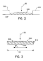
- a target button 10 is shown, having a stepped configuration. Stress in the X-ray producing section 20 is reduced by minimizing the overall thickness 25 of the button to that which is necessary for X-ray production, and reducing the diameter 27 of the X-ray producing region of the button by incorporating step interface 30. It is recognized by those skilled in the art that thickness 25 will be application dependent and is primarily based upon incident electron energy of the beam. Stress is likewise reduced at the interface 35 between the high Z button and the low Z substrate (not shown), by spreading the interface over a larger region through lip section 40, whose diameter extends beyond step 30 a distance such that the overall diameter of the button is approximately twice diameter 27 of the X-ray producing section.
- a target button so configured, when heated at its central location as a result of electron beam 50, will reduce both the high Z button and substrate interface stresses created as a result of said heating.
- similar geometric configuration may be obtained by providing masking elements 200 on substrate 220, and using a chemical vapor deposition (CVD) process, such as those well known in the art, to create region 230 of the dimensions herein described.
- CVD chemical vapor deposition
- an expansion gap 300 is created in a high Z button 310 such that diameter 23 is approximately twice that of diameter 27.
- FE finite element
- a solid continuum is subdivided into smaller subregions, or elements, which are connected along their boundaries and at their corners by points called nodes.
- the material properties of the solid and the governing relations for the specific type of analysis are considered by the code and expressed in terms of unknowns at the nodes.
- An assembly process which considers applied loads and boundary conditions results in a system of simultaneous equations, which when solved, yields an approximate behavior of the structure.
- a commercially available code is used for the analysis conducted. The code was checked by test and correlation of computed results with observed X-ray target behavior (Cook, Robert D. Concepts and Applications of Finite Element Analysis, John Wiley & Sons, 2nd ed. 1981 for a description of the Finite Element method).
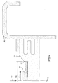
- the target was modeled as a 2-D axisymetric section. Material properties, heat loading from beam impact and convection cooling were added to complete the model. A typical FE mesh is shown in Fig. 4. Location of beam impact (50), water cooling (15) and axis of revolution (16) are also shown.
- the stepped button geometry was arrived at by recognizing and satisfying the following conditions: 1) reducing button diameter reduces the magnitude of stress in the button, and 2) increasing button diameter reduces the magnitude of stress in the substrate at button edge. Additionally, the full thickness of button is necessary only in the region of beam impact.
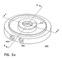
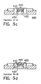
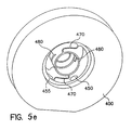
- FIG. 5 a-f another aspect of the present invention is a support structure 400 as shown in Figs. 5 a-f.
- Prior art designs have focused on radiological and thermal aspects of the support design, ignoring the flexibility of the support structure.
- Heating induced stresses are not restricted to the vicinity of beam impact in the button or in the substrate.
- Deformations resulting from elevated temperatures occur throughout the target structure. Therefore, if the structure is overly constrained high stress and thermal fatigue result. Fatigue cracks in the support structure and substrate can potentially propagate through a vacuum wall, creating vacuum leaks. Additionally, thermal fatigue of the high/low Z interface can result in loss of thermal contact and ultimate failure.
- Support structure 400 allows free expansion of the substrate during operation.
- a high Z button of the present invention is shown bonded to low Z substrate 430, such as copper.
- substrate 430 is of conventional design well known in the art, having integral coolant channels 440, whose location is optimized utilizing FE technique as provided herein to allow the water or other cooling media to flow as close as possible to the heated target without allowing the temperature of the inner walls of the channels to exceed the boiling point of the fluid.
- This substrate button assembly is then incorporated into flexible support structure 400.
- Structure 400 is preferably manufactured from a solid piece of SST (stainless steel), incorporating an integral coolant supply channel 450 and return channel 455, which are operably coupled to a pair of supply and return plenum chambers, designated as elements 460 and 465 respectively.
- SST stainless steel
- Stainless steel is preferred in view of its ability to be easily welded without the need for a separate weldable member, and the ability to minimize wall thickness for structural flexibility without sacrificing vacuum integrity.
- Supply plenum chamber 460 is separated from return plenum 465 by an arrangement of flexible baffles 470.
- Horizontal slots 480 shown in Fig.
- baffle elements 470 which separate the plenum supply chamber 460 from the return chamber 465, provide maximum flexibility and minimal restriction during radial expansion of the target as a result of heating during X-ray generation. Coolant supplied by channel 450 flows to slot 480 where it encounters substrate 430, and subsequently splits as it enters substrate coolant channel 440. Coolant flows equally around both sides of the heated section of the substrate, where it ultimately recombines for flow into return plenum chamber 465 via slot 480, for return through channel 455.
- Fig. 6a the plenum chambers are replaced by a cylinderical support 710, having cooling channels disposed therein.
- Support 710 upholds the high Z button/substrate combination, while supplying coolant directly to the substrate via manifold 720.
- Fig. 6b depicts an isolated view of manifold 720, with one manifold arm acting as a supply arm, being coupled to support 710 and in fluid communication therewith, with the other manifold arm likewise coupled to support 710, and acting as a return arm for coolant flow.
- coolant enters the supply arm of manifold 720, and splits upon entering support 710, flowing around either side of the cylinderical structure and then recombines within the return arm of manifold 720.
Landscapes
- X-Ray Techniques (AREA)
Description
Claims (5)
- A stationary target of an X-ray generating device for converting kinetic energy of a beam (50) of high energy electrons into X-rays, comprising an anode button (10) upon which the electron beam (50) is directed, formed of a high Z material, said button (10) having an X-ray producing section (20) and a lip section (40), characterized by said lip section (40) having a greater lateral extent than said X-ray producing section (20) and forming a stepped configuration therewith, and the X-ray producing section (20) being thicker than the lip section (40).
- The stationary target of claim 1, wherein a diameter of said lip section (40) is approximately twice exceeding a diameter of said X-ray producing section (20).
- The stationary target of claim 1 or 2, further comprising a substrate (430) formed of a low Z material, said substrate being attached to said lip section (40).
- The stationary target of claim 3, wherein said substrate (430) further comprises integral cooling channels (440).
- The stationary target of claim 1, 2, 3 or 4, further comprising a support structure (400) for housing said substrate (430) to provide minimum resistance to said anode button (10) when said anode button (10) expands during X-ray production.
Applications Claiming Priority (3)
| Application Number | Priority Date | Filing Date | Title |
|---|---|---|---|
| US43068295A | 1995-04-28 | 1995-04-28 | |
| US430682 | 1995-04-28 | ||
| PCT/IB1996/000438 WO1996034404A1 (en) | 1995-04-28 | 1996-04-16 | High output stationary x-ray target with flexible support structure |
Publications (3)
| Publication Number | Publication Date |
|---|---|
| EP0767967A1 EP0767967A1 (en) | 1997-04-16 |
| EP0767967A4 EP0767967A4 (en) | 1997-10-01 |
| EP0767967B1 true EP0767967B1 (en) | 2002-01-02 |
Family
ID=23708581
Family Applications (1)
| Application Number | Title | Priority Date | Filing Date |
|---|---|---|---|
| EP96911083A Expired - Lifetime EP0767967B1 (en) | 1995-04-28 | 1996-04-16 | High output stationary x-ray target |
Country Status (4)
| Country | Link |
|---|---|
| US (1) | US5680433A (en) |
| EP (1) | EP0767967B1 (en) |
| JP (1) | JPH10502769A (en) |
| WO (1) | WO1996034404A1 (en) |
Families Citing this family (28)
| Publication number | Priority date | Publication date | Assignee | Title |
|---|---|---|---|---|
| US6907106B1 (en) | 1998-08-24 | 2005-06-14 | Varian Medical Systems, Inc. | Method and apparatus for producing radioactive materials for medical treatment using x-rays produced by an electron accelerator |
| US7466799B2 (en) * | 2003-04-09 | 2008-12-16 | Varian Medical Systems, Inc. | X-ray tube having an internal radiation shield |
| NL1028481C2 (en) * | 2005-03-08 | 2006-09-11 | Univ Delft Tech | Micro X-ray source. |
| WO2008144425A2 (en) * | 2007-05-16 | 2008-11-27 | Passport Systems, Inc. | A thin walled tube radiator for bremsstrahlung at high electron beam intensities |
| US9305735B2 (en) | 2007-09-28 | 2016-04-05 | Brigham Young University | Reinforced polymer x-ray window |
| US8736138B2 (en) | 2007-09-28 | 2014-05-27 | Brigham Young University | Carbon nanotube MEMS assembly |
| US8498381B2 (en) | 2010-10-07 | 2013-07-30 | Moxtek, Inc. | Polymer layer on X-ray window |
| DE102008017153A1 (en) * | 2008-04-03 | 2009-11-12 | Siemens Aktiengesellschaft | radiation generator |
| US8247971B1 (en) | 2009-03-19 | 2012-08-21 | Moxtek, Inc. | Resistively heated small planar filament |
| US7831021B1 (en) | 2009-08-31 | 2010-11-09 | Varian Medical Systems, Inc. | Target assembly with electron and photon windows |
| US7983394B2 (en) * | 2009-12-17 | 2011-07-19 | Moxtek, Inc. | Multiple wavelength X-ray source |
| US8526574B2 (en) | 2010-09-24 | 2013-09-03 | Moxtek, Inc. | Capacitor AC power coupling across high DC voltage differential |
| US8995621B2 (en) | 2010-09-24 | 2015-03-31 | Moxtek, Inc. | Compact X-ray source |
| US8804910B1 (en) | 2011-01-24 | 2014-08-12 | Moxtek, Inc. | Reduced power consumption X-ray source |
| US8750458B1 (en) | 2011-02-17 | 2014-06-10 | Moxtek, Inc. | Cold electron number amplifier |
| US8929515B2 (en) | 2011-02-23 | 2015-01-06 | Moxtek, Inc. | Multiple-size support for X-ray window |
| US8792619B2 (en) | 2011-03-30 | 2014-07-29 | Moxtek, Inc. | X-ray tube with semiconductor coating |
| US9174412B2 (en) | 2011-05-16 | 2015-11-03 | Brigham Young University | High strength carbon fiber composite wafers for microfabrication |
| US8989354B2 (en) | 2011-05-16 | 2015-03-24 | Brigham Young University | Carbon composite support structure |
| US9076628B2 (en) | 2011-05-16 | 2015-07-07 | Brigham Young University | Variable radius taper x-ray window support structure |
| US8817950B2 (en) | 2011-12-22 | 2014-08-26 | Moxtek, Inc. | X-ray tube to power supply connector |
| US8761344B2 (en) | 2011-12-29 | 2014-06-24 | Moxtek, Inc. | Small x-ray tube with electron beam control optics |
| US9072154B2 (en) | 2012-12-21 | 2015-06-30 | Moxtek, Inc. | Grid voltage generation for x-ray tube |
| US9184020B2 (en) | 2013-03-04 | 2015-11-10 | Moxtek, Inc. | Tiltable or deflectable anode x-ray tube |
| US9177755B2 (en) | 2013-03-04 | 2015-11-03 | Moxtek, Inc. | Multi-target X-ray tube with stationary electron beam position |
| US9173623B2 (en) | 2013-04-19 | 2015-11-03 | Samuel Soonho Lee | X-ray tube and receiver inside mouth |
| CN107546090B (en) * | 2017-09-19 | 2024-04-05 | 同方威视技术股份有限公司 | X-ray conversion target |
| US11217355B2 (en) * | 2017-09-29 | 2022-01-04 | Uchicago Argonne, Llc | Compact assembly for production of medical isotopes via photonuclear reactions |
Family Cites Families (9)
| Publication number | Priority date | Publication date | Assignee | Title |
|---|---|---|---|---|
| NL297881A (en) * | 1962-09-15 | |||
| AT265449B (en) * | 1966-09-09 | 1968-10-10 | Plansee Metallwerk | Rotating anode for X-ray tubes |
| US3609432A (en) * | 1968-11-08 | 1971-09-28 | Rigaku Denki Co Ltd | Thin target x-ray tube with means for protecting the target |
| NL7115946A (en) * | 1971-11-19 | 1973-05-22 | ||
| NL7214642A (en) * | 1972-10-28 | 1974-05-01 | ||
| US3973156A (en) * | 1974-01-23 | 1976-08-03 | U.S. Philips Corporation | Anode disc for an X-ray tube comprising a rotary anode |
| JPS5682557A (en) * | 1979-12-10 | 1981-07-06 | Mitsubishi Electric Corp | Particle accelerator |
| GB2089109B (en) * | 1980-12-03 | 1985-05-15 | Machlett Lab Inc | X-rays targets and tubes |
| JPS57154756A (en) * | 1981-03-20 | 1982-09-24 | Toshiba Corp | Rotary anode for x-ray tube |
-
1996
- 1996-03-25 US US08/624,143 patent/US5680433A/en not_active Expired - Lifetime
- 1996-04-16 WO PCT/IB1996/000438 patent/WO1996034404A1/en not_active Ceased
- 1996-04-16 JP JP8532325A patent/JPH10502769A/en active Pending
- 1996-04-16 EP EP96911083A patent/EP0767967B1/en not_active Expired - Lifetime
Also Published As
| Publication number | Publication date |
|---|---|
| WO1996034404A1 (en) | 1996-10-31 |
| US5680433A (en) | 1997-10-21 |
| EP0767967A1 (en) | 1997-04-16 |
| JPH10502769A (en) | 1998-03-10 |
| EP0767967A4 (en) | 1997-10-01 |
Similar Documents
| Publication | Publication Date | Title |
|---|---|---|
| US5680433A (en) | High output stationary X-ray target with flexible support structure | |
| US6490340B1 (en) | X-ray generating apparatus | |
| US5069274A (en) | Spacecraft radiator system | |
| JPH11510955A (en) | X-ray generator having heat transfer device | |
| WO1995006952A1 (en) | X-ray tubes | |
| TWI810448B (en) | heat sink | |
| US8000450B2 (en) | Aperture shield incorporating refractory materials | |
| EP3457425B1 (en) | X-ray conversion target | |
| US7302044B2 (en) | X-ray generator tube comprising an orientable target carrier system | |
| US5995585A (en) | X-ray tube having electron collector | |
| US7410296B2 (en) | Electron absorption apparatus for an x-ray device | |
| JP5542855B2 (en) | X-ray tube device and X-ray tube | |
| JP2005135908A5 (en) | ||
| US8130910B2 (en) | Liquid-cooled aperture body in an x-ray tube | |
| CN115802577B (en) | High heat-carrying neutron target system | |
| JP4326300B2 (en) | Plasma CVD apparatus and electrode for plasma CVD apparatus | |
| CN214898323U (en) | X-ray tube | |
| IL180440A (en) | Compact source of a high-brightness x-ray beam | |
| US7668298B2 (en) | System and method for collecting backscattered electrons in an x-ray tube | |
| CN219288056U (en) | Beam window structure | |
| WO2007026612A1 (en) | X-ray tube | |
| Youchison et al. | Critical heat flux performance of hypervapotrons proposed for use in the ITER divertor vertical target | |
| US20060291607A1 (en) | Target apparatus | |
| EP2873086B1 (en) | Cooling arrangement for x-ray generator | |
| CN221079927U (en) | Copper-based high-heat-conductivity composite material conversion target and X-ray tube |
Legal Events
| Date | Code | Title | Description |
|---|---|---|---|
| PUAI | Public reference made under article 153(3) epc to a published international application that has entered the european phase |
Free format text: ORIGINAL CODE: 0009012 |
|
| 17P | Request for examination filed |
Effective date: 19961230 |
|
| AK | Designated contracting states |
Kind code of ref document: A1 Designated state(s): FR GB |
|
| A4 | Supplementary search report drawn up and despatched |
Effective date: 19970814 |
|
| AK | Designated contracting states |
Kind code of ref document: A4 Designated state(s): FR GB |
|
| 17Q | First examination report despatched |
Effective date: 19980828 |
|
| RAP1 | Party data changed (applicant data changed or rights of an application transferred) |
Owner name: VARIAN MEDICAL SYSTEMS, INC. |
|
| RTI1 | Title (correction) |
Free format text: HIGH OUTPUT STATIONARY X-RAY TARGET |
|
| GRAG | Despatch of communication of intention to grant |
Free format text: ORIGINAL CODE: EPIDOS AGRA |
|
| RTI1 | Title (correction) |
Free format text: HIGH OUTPUT STATIONARY X-RAY TARGET |
|
| GRAG | Despatch of communication of intention to grant |
Free format text: ORIGINAL CODE: EPIDOS AGRA |
|
| GRAH | Despatch of communication of intention to grant a patent |
Free format text: ORIGINAL CODE: EPIDOS IGRA |
|
| GRAH | Despatch of communication of intention to grant a patent |
Free format text: ORIGINAL CODE: EPIDOS IGRA |
|
| GRAA | (expected) grant |
Free format text: ORIGINAL CODE: 0009210 |
|
| REG | Reference to a national code |
Ref country code: GB Ref legal event code: IF02 |
|
| AK | Designated contracting states |
Kind code of ref document: B1 Designated state(s): FR GB |
|
| ET | Fr: translation filed | ||
| PLBE | No opposition filed within time limit |
Free format text: ORIGINAL CODE: 0009261 |
|
| STAA | Information on the status of an ep patent application or granted ep patent |
Free format text: STATUS: NO OPPOSITION FILED WITHIN TIME LIMIT |
|
| 26N | No opposition filed | ||
| REG | Reference to a national code |
Ref country code: GB Ref legal event code: 732E |
|
| REG | Reference to a national code |
Ref country code: FR Ref legal event code: TP |
|
| PGFP | Annual fee paid to national office [announced via postgrant information from national office to epo] |
Ref country code: FR Payment date: 20090417 Year of fee payment: 14 |
|
| REG | Reference to a national code |
Ref country code: FR Ref legal event code: ST Effective date: 20101230 |
|
| PGFP | Annual fee paid to national office [announced via postgrant information from national office to epo] |
Ref country code: GB Payment date: 20110426 Year of fee payment: 16 |
|
| PG25 | Lapsed in a contracting state [announced via postgrant information from national office to epo] |
Ref country code: FR Free format text: LAPSE BECAUSE OF NON-PAYMENT OF DUE FEES Effective date: 20100430 |
|
| GBPC | Gb: european patent ceased through non-payment of renewal fee |
Effective date: 20120416 |
|
| PG25 | Lapsed in a contracting state [announced via postgrant information from national office to epo] |
Ref country code: GB Free format text: LAPSE BECAUSE OF NON-PAYMENT OF DUE FEES Effective date: 20120416 |