EP0767952B1 - Light beam deflecting device - Google Patents
Light beam deflecting device Download PDFInfo
- Publication number
- EP0767952B1 EP0767952B1 EP96911909A EP96911909A EP0767952B1 EP 0767952 B1 EP0767952 B1 EP 0767952B1 EP 96911909 A EP96911909 A EP 96911909A EP 96911909 A EP96911909 A EP 96911909A EP 0767952 B1 EP0767952 B1 EP 0767952B1
- Authority
- EP
- European Patent Office
- Prior art keywords
- reflector
- light
- face
- sleeve
- optical axis
- Prior art date
- Legal status (The legal status is an assumption and is not a legal conclusion. Google has not performed a legal analysis and makes no representation as to the accuracy of the status listed.)
- Expired - Lifetime
Links
- 230000003287 optical effect Effects 0.000 claims description 16
- XAGFODPZIPBFFR-UHFFFAOYSA-N aluminium Chemical compound [Al] XAGFODPZIPBFFR-UHFFFAOYSA-N 0.000 claims description 2
- 229910052782 aluminium Inorganic materials 0.000 claims description 2
- 239000011248 coating agent Substances 0.000 claims description 2
- 238000000576 coating method Methods 0.000 claims description 2
- PCHJSUWPFVWCPO-UHFFFAOYSA-N gold Chemical compound [Au] PCHJSUWPFVWCPO-UHFFFAOYSA-N 0.000 claims description 2
- 239000010931 gold Substances 0.000 claims description 2
- 229910052737 gold Inorganic materials 0.000 claims description 2
- 230000005540 biological transmission Effects 0.000 claims 4
- 239000004411 aluminium Substances 0.000 claims 1
- 239000000463 material Substances 0.000 description 8
- 238000011109 contamination Methods 0.000 description 3
- 238000004519 manufacturing process Methods 0.000 description 2
- 238000004026 adhesive bonding Methods 0.000 description 1
- 201000009310 astigmatism Diseases 0.000 description 1
- 230000015572 biosynthetic process Effects 0.000 description 1
- 230000000295 complement effect Effects 0.000 description 1
- 238000011161 development Methods 0.000 description 1
- 230000018109 developmental process Effects 0.000 description 1
- 239000000428 dust Substances 0.000 description 1
- 230000005693 optoelectronics Effects 0.000 description 1
- 239000002245 particle Substances 0.000 description 1
- 230000001850 reproductive effect Effects 0.000 description 1
- 239000013585 weight reducing agent Substances 0.000 description 1
Images

Classifications
-
- G—PHYSICS
- G02—OPTICS
- G02B—OPTICAL ELEMENTS, SYSTEMS OR APPARATUS
- G02B7/00—Mountings, adjusting means, or light-tight connections, for optical elements
- G02B7/18—Mountings, adjusting means, or light-tight connections, for optical elements for prisms; for mirrors
- G02B7/182—Mountings, adjusting means, or light-tight connections, for optical elements for prisms; for mirrors for mirrors
- G02B7/1821—Mountings, adjusting means, or light-tight connections, for optical elements for prisms; for mirrors for mirrors for rotating or oscillating mirrors
-
- G—PHYSICS
- G02—OPTICS
- G02B—OPTICAL ELEMENTS, SYSTEMS OR APPARATUS
- G02B26/00—Optical devices or arrangements for the control of light using movable or deformable optical elements
- G02B26/08—Optical devices or arrangements for the control of light using movable or deformable optical elements for controlling the direction of light
- G02B26/10—Scanning systems
-
- G—PHYSICS
- G02—OPTICS
- G02B—OPTICAL ELEMENTS, SYSTEMS OR APPARATUS
- G02B27/00—Optical systems or apparatus not provided for by any of the groups G02B1/00 - G02B26/00, G02B30/00
- G02B27/0025—Optical systems or apparatus not provided for by any of the groups G02B1/00 - G02B26/00, G02B30/00 for optical correction, e.g. distorsion, aberration
- G02B27/0031—Optical systems or apparatus not provided for by any of the groups G02B1/00 - G02B26/00, G02B30/00 for optical correction, e.g. distorsion, aberration for scanning purposes
Definitions
- the invention relates to the field of electronic reproduction technology and relates to a light beam deflector in a scanner for document scanners or for recording devices.
- a scanner essentially has a light source, for example a laser light source, the generates a light beam by means of the rotating light beam deflecting device is periodically distracted by an object.
- a document scanner also called an input scanner
- one in one Scanning device generated light beam pixel and line by line over a to be scanned Template, and the one reflected or transmitted by the template Scanning light is converted into an image signal in an optoelectronic converter.
- a recording device also called a recorder, imagesetter or output scanner
- the light beam obtained in a scanning device is used for recording of information is modulated in intensity by an image signal and pixel by pixel and line by line passed over a light-sensitive material.
- the holder for the template or the recording material In the case of a flatbed device, the holder for the template or the recording material a flat surface over which the light beam pixel and line by line is guided, and which moves relative to the scanner.
- a Inner drum device is the holder for the template or for the recording material designed as a stationary half-shell or trough. The scanner moves parallel to the longitudinal axis of the bracket, and the light beam is perpendicular to the longitudinal axis radially over the template or the Recorded material led.
- An inner drum recorder is for example from EP-A-0 354 028 known.
- the light beam deflecting device is there as one transverse to the direction of light propagation arranged reflecting surface formed with a rotating Shaft is connected. With the help of the reflecting surface, the light beam turns on Recording material directed.
- Contamination can occur during operation of the recording device accumulate on the reflecting surface and it can be due to the Rotational axis asymmetrical design at high speeds air turbulence arise. This air turbulence leads to noise, cause additional dirt in the area of the reflection surface and impair the even rotation of the reflecting surface.
- a light beam deflection device with a Light entry surface and a light exit surface for the vertically deflected Light beam known from a rotatably mounted carrier prism and from a translucent deflection prism extending in the direction of an axis of rotation consists.
- the surface of the deflection prism adjacent to the carrier prism is designed as a reflection surface that runs transversely to the axis of rotation.
- the Deflection prism is glued to the carrier prism, and both prisms complement each other at least in regions to a symmetrical one with respect to the axis of rotation Unit.
- Disc-shaped cover elements are on the side of the unit arranged which protrude beyond the unit in the radial extent.
- a further light beam deflection device which of a transparent body designed as a spherical segment, which a Light entry surface, a reflection surface and a light exit surface and consists of a carrier body, which is also designed as a spherical segment, and which the reflection layer is glued to the transparent body.
- the one from the transparent body and the support body is formed by a unit Light entry surface rotatable vertical axis and has an at least in With respect to the axis, the outer contour is rotationally symmetrical.
- EP-A-0 475 399 is a further light beam deflecting device for one Inner drum imagesetter known in which the reflector is of a cylindrical Surrounded sleeve, which has a light entry opening for one at the front incident light beam and on the outer surface a light exit surface for the has the deflected light beam.
- the reflector is already protected by a sleeve, but can still Dust particles through the light entry surface or the light exit surface into the interior get and dirty the reflector.
- Light sources are preferred for exposing certain recording materials Laser light sources needed with higher light outputs.
- the light beam deflecting device must deflect a light beam of longer wavelength have a correspondingly large entrance aperture in order to, despite the larger wavelength of the light beam comparable pixel sizes and line widths to get on exposure.
- the object of the present invention is therefore to provide a focusing light beam deflection device to train such that they have a large entrance aperture for the has incident light beam to an emerging light beam with small Generate point size and still air turbulence and uneven running reduced and contamination of the mirror surfaces can be prevented.
- Fig. 1 shows a longitudinal section through the light beam deflection device according to the invention.
- a reflector (1) is connected to a support (2) which is rotatable mounted shaft (3) is coupled.
- the shaft (3) is guided in a holder (4).
- the reflector (1) is formed within a sleeve (5) that is rotationally symmetrical Housing arranged, which is connected to the carrier (2).
- the connection can be done with screws (6).
- the hollow cylindrical sleeve (5) has on the end facing away from the reflector (1) a light inlet opening (7) and a light exit opening (8) in the lateral surface.
- At least one lens is preferably located in the light entry opening (7) an achromatic (9) which is arranged symmetrically to an optical axis (10).
- the optical axis (10) simultaneously forms the axis of rotation for the light beam deflection device.
- the achromatic (9) can be displaced in the direction of the optical axis (10) for the purpose of adjustment and after adjustment in the final position in the sleeve (5), for example by gluing.
- the adjustment is made such that a reflected light beam (11) is focused on an object plane (12).
- the light exit opening (8) is closed by a transparent insert (13), the one flat inner light passage surface (14) and one flat outer light passage surface (15).
- the light passage surfaces (14; 15) are more preferred Aligned wedge-shaped to each other, with the outer light passage surface (15) parallel to the optical axis (10) or parallel to the surface line of the sleeve (5) is oriented.
- the angle between the wedge-shaped ones Light passage surfaces (14; 15) can be used depending on the respective reflection angle of the light beam (11) vary.
- the wedge-shaped, transparent insert (13) is glued into the light exit opening (8). By means of the wedge-shaped insert (13) an astigmatism correction can advantageously be carried out.
- Insert (13) on the outer contour of the sleeve (5) has the outer boundary of the insert (13) preferably on oblique flanks (16) so that the cross-sectional area of the insert (12) essentially trapezoidal in both dimensions is trained.
- the reflector (1) has a reflection surface oriented obliquely to the optical axis (10) (17) or mirror surface.
- the reflector (1) consists of, for example polished aluminum, and the reflection surface (17) has, for example, a gold coating on.
- the angle of inclination ( ⁇ ) of the reflection surface (17) relative to the optical Axis (10) can be, for example, in the range from 45 ° to 70 °. By doing In the illustrated embodiment, the angle of inclination ( ⁇ ) is, for example, 65 °.
- a resistant embodiment of the reflector (1) is achieved in that the reflector (1) has a substantially cylindrical basic shape, and the Reflection surface (17) is designed as an obliquely arranged cylindrical section.
- the light beam (11) generated in a stationary light source falls through the light entry opening (7) and the achromatic lens (9) onto the reflection surface (17) of the reflector (1).
- the light beam (11) deflected from the reflection surface (17) passes through the light exit opening (8) onto the object plane (12), on which, in the case that the light beam deflector is used in an imagesetter, too exposing recording material is fixed.
- the arrangement of the reflector (1) results in a sleeve-shaped housing advantageously a compact light beam deflecting device that is essentially one has rotationally symmetrical outer contour.
- the sleeve (5) is provided with a circumferential flange (18) in the bores (19) for the passage of the screws (6) are arranged.
- the screws (6) engage with external threads in the internal thread of the carrier (2).
- the carrier (2) receives an end piece of the shaft (3) in a recess (20).
- the carrier (2) has a centering pin (21) which is in a centering hole (22) of the reflector (1) is inserted, the centering hole (22) and the centering pin (21) extend symmetrically to the optical axis (10).
- the achromatic (9) is held by an insert (23) which is relative to the sleeve (5) in the direction of optical axis (10) for the purpose of focusing the light beam (11) is displaceable.
- the reflector (1) has weight compensation bores (24) in order to create an optical one Axis (10) symmetrical material distribution and at the same time a weight reduction to reach.
- the weight compensation bores (24) extend from the support (2) of the reflector (1) towards the reflection surface (17) without to penetrate them.
- weight compensation holes (24) are provided.
- a effective arrangement of the counterbalance holes (24) is produced by that they extend along the outer circumference of the reflector (1).
- Adjacent weight compensation bores (24) are space-saving Order reached.
- the light beam deflection device By using the light beam deflection device according to the invention, it is possible, an enlarged entrance aperture corresponding to the larger wavelength use and despite the larger wavelength comparable line widths and To generate pixel or point sizes.
- the light beam deflection device also used to deflect light rays of shorter wavelengths be, an improvement over the prior art also Smooth running and a reduction in the tendency to soiling can be achieved.
- the Light beam deflecting device also has the advantage that it is modular is built, whereby each building module individually with respect to the axis of rotation balanced and thus the production can be simplified.
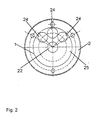
- Fig. 2 shows a top view of the reflector (1) the position of the counterbalance holes (24) relative to the center hole (22).
- the positioning of the counterbalance holes (24) is chosen such that both a high stability and a symmetrical weight distribution with respect to the optical axis (10) as the axis of rotation become.
- the reflector (1) is mounted on the support (2), over which a Cylinder gate (25) with the invisible reflection surface (17) rises.
Landscapes
- Physics & Mathematics (AREA)
- General Physics & Mathematics (AREA)
- Optics & Photonics (AREA)
- Mechanical Optical Scanning Systems (AREA)
- Facsimile Scanning Arrangements (AREA)
Description
Die Erfindung bezieht sich auf das Gebiet der elektronischen Reproduktionstechnik und betrifft eine Lichtstrahl-Ablenkvorrichtung in einer Abtasteinrichtung für Vorlagen-Abtastgeräte oder für Aufzeichnungsgeräte. Eine solche Abtasteinrichtung weist im wesentlichen eine Lichtquelle auf, beispielsweise eine Laserlichtquelle, die einen Lichtstrahl erzeugt, der mittels der rotierenden Lichtstrahl-Ablenkvorrichtung periodisch über ein Objekt abgelenkt wird.The invention relates to the field of electronic reproduction technology and relates to a light beam deflector in a scanner for document scanners or for recording devices. Such a scanner essentially has a light source, for example a laser light source, the generates a light beam by means of the rotating light beam deflecting device is periodically distracted by an object.
Bei einem Vorlagen-Abtastgerät, auch Eingabe-Scanner genannt, wird ein in einer Abtasteinrichtung erzeugter Lichtstrahl pixel- und zeilenweise über eine abzutastende Vorlage geführt, und das von der Vorlage reflektierte oder durchgelassene Abtastlicht in einem optoelektronischen Wandler in ein Bildsignal umgewandelt. Bei einem Aufzeichnungsgerät, auch Recorder, Belichter oder Ausgabe-Scanner genannt, wird der in einer Abtasteinrichtung gewonnene Lichtstrahl zur Aufzeichnung von Informationen durch ein Bildsignal intensitätsmoduliert und pixel- und zeilenweise über ein lichtempfindliches Aufzeichnungsmaterial geführt.In a document scanner, also called an input scanner, one in one Scanning device generated light beam pixel and line by line over a to be scanned Template, and the one reflected or transmitted by the template Scanning light is converted into an image signal in an optoelectronic converter. At a recording device, also called a recorder, imagesetter or output scanner, the light beam obtained in a scanning device is used for recording of information is modulated in intensity by an image signal and pixel by pixel and line by line passed over a light-sensitive material.
Im Falle eines Flachbett-Gerätes ist die Halterung für die Vorlage bzw. das Aufzeichnungsmaterial eine ebene Fläche, über die der Lichtstrahl pixel- und zeilenweise geführt wird, und die sich relativ zur Abtasteinrichtung bewegt. Im Falle eines Innentrommel-Gerätes ist die Halterung für die Vorlage bzw. für das Aufzeichnungsmaterial als stationäre Halbschale oder Mulde ausgebildet. Die Abtasteinrichtung bewegt sich parallel zur Längsachse der Halterung, und der Lichtstrahl wird senkrecht zur Längsachse radial über die Vorlage bzw. das Aufzeichnungsmaterial geführt.In the case of a flatbed device, the holder for the template or the recording material a flat surface over which the light beam pixel and line by line is guided, and which moves relative to the scanner. in case of a Inner drum device is the holder for the template or for the recording material designed as a stationary half-shell or trough. The scanner moves parallel to the longitudinal axis of the bracket, and the light beam is perpendicular to the longitudinal axis radially over the template or the Recorded material led.
Ein Innentrommel-Aufzeichnungsgerät ist beispielsweise aus der EP-A-0 354 028 bekannt. Die Lichtstrahl-Ablenkvorrichtung ist dort als eine quer zur Lichtausbreitungsrichtung angeordnete spiegelnde Fläche ausgebildet, die mit einer rotierenden Welle verbunden ist. Mit Hilfe der spiegelnden Fläche wird der Lichtstrahl auf ein Aufzeichnungsmaterial geleitet. An inner drum recorder is for example from EP-A-0 354 028 known. The light beam deflecting device is there as one transverse to the direction of light propagation arranged reflecting surface formed with a rotating Shaft is connected. With the help of the reflecting surface, the light beam turns on Recording material directed.
Während des Betriebes des Aufzeichnungsgerätes können sich Verunreinigungen an der spiegelnden Fläche ansammeln und es können aufgrund der bezüglich der Rotationsachse unsymmetrischen Gestaltung bei hohen Drehzahlen Luftturbulenzen entstehen. Diese Luftturbulenzen führen zu Geräuschbelästigungen, verursachen zusätzliche Verschmutzungen im Bereich der Reflexionsfläche und beeinträchtigen die gleichmäßige Rotation der spiegelnden Fläche.Contamination can occur during operation of the recording device accumulate on the reflecting surface and it can be due to the Rotational axis asymmetrical design at high speeds air turbulence arise. This air turbulence leads to noise, cause additional dirt in the area of the reflection surface and impair the even rotation of the reflecting surface.
Aus der DE-A-41 24 229 ist bereits eine Lichtstrahl-Ablenkvorrichtung mit einer Lichteintrittsfläche und einer Lichtaustrittsfläche für den senkrecht abgelenkten Lichtstrahl bekannt, die aus einem rotationsfähig gelagerten Trägerprisma und aus einem sich in Richtung einer Rotationsachse erstreckenden, lichtdurchläßigen Ablenkprisma besteht. Die an das Trägerprisma angrenzende Fläche des Ablenkprismas ist als Reflexionsfläche ausgebildet, die quer zur Rotationsachse verläuft. Das Ablenkprisma ist mit dem Trägerprisma verklebt, und beide Prismen ergänzen sich mindestens bereichsweise zu einer bezüglich der Rotationsachse symmetrischen Einheit. Seitlich der Einheit sind scheibenförmige Abdeckungselemente angeordnet, welche die Einheit in der radialen Ausdehnung überkragen.From DE-A-41 24 229 there is already a light beam deflection device with a Light entry surface and a light exit surface for the vertically deflected Light beam known from a rotatably mounted carrier prism and from a translucent deflection prism extending in the direction of an axis of rotation consists. The surface of the deflection prism adjacent to the carrier prism is designed as a reflection surface that runs transversely to the axis of rotation. The Deflection prism is glued to the carrier prism, and both prisms complement each other at least in regions to a symmetrical one with respect to the axis of rotation Unit. Disc-shaped cover elements are on the side of the unit arranged which protrude beyond the unit in the radial extent.
Bei dieser Lichtstrahl-Ablenkvorrichtung treten durch die Abdeckungselemente zwar nur geringe Luftturbulenzen, Verschmutzungen sowie Laufunruhe auf, die Herstellung ist aber vergleichsweise aufwendig, da die Abdeckungselemente genau gefertigt und an der Einheit präzise zentriert werden müssen.In this light beam deflecting device pass through the cover elements only slight air turbulence, pollution and uneven running, which Production is comparatively complex because the cover elements are accurate must be manufactured and precisely centered on the unit.
Aus der DE-A-41 30 977 ist eine weitere Lichtstrahl-Ablenkvorrichtung bekannt, die aus einem als Kugelsegment ausgebildeten, transparenten Körper, welcher eine Lichteintrittsfläche, eine Reflexionsfläche und eine Lichtaustrittsfläche aufweist und aus einem ebenfalls als Kugelsegment ausgebildeten Trägerkörper besteht, der an der Reflexionsschicht mit dem transparenten Körper verklebt ist. Die aus dem transparenten Körper und dem Trägerkörper gebildete Einheit ist um eine zur Lichteintrittsfläche senkrecht stehende Achse drehbar und weist eine zumindest in Bezug auf die Achse rotationssymmetrische Außenkontur auf. Durch die kugelförmige Ausbildung der Lichtstrahl-Ablenkvorrichtung kann diese mit einer relativ hohen Drehzahl rotieren, ohne daß wesentliche Luftturbulenzen und Laufgeräusche entstehen.From DE-A-41 30 977 a further light beam deflection device is known which of a transparent body designed as a spherical segment, which a Light entry surface, a reflection surface and a light exit surface and consists of a carrier body, which is also designed as a spherical segment, and which the reflection layer is glued to the transparent body. The one from the transparent body and the support body is formed by a unit Light entry surface rotatable vertical axis and has an at least in With respect to the axis, the outer contour is rotationally symmetrical. Through the spherical Formation of the light beam deflection device can be done with a relative rotate at high speed without significant air turbulence and running noise arise.
Aus der EP-A-0 475 399 nach der Anspruch 1 abgegrengt ist, ist eine weitere Lichtstrahl-Ablenkvorrichtung für einen
Innentrommel-Belichter bekannt, bei der der Reflektor von einer zylinderförmigen
Hülse umgeben ist, welche an der Stirnseite eine Lichteintrittsöffnung für einen
einfallenden Lichtstrahl und an der Mantelfläche eine Lichtaustrittsfläche für den an
dem Reflektor abgelenkten Lichtstrahl aufweist. Bei dieser Lichtstrahl-Ablenkvorrichtung
ist der Reflektor bereits durch eine Hülse geschützt, dennoch können
Staubpartikel durch die Lichteintrittsfläche oder die Lichtaustrittsfläche in das Innere
gelangen und den Reflektor verschmutzen.EP-A-0 475 399, according to which
Zur Belichtung bestimmter Aufzeichnungsmaterialien werden Lichtquellen, vorzugsweise Laserlichtquellen, mit höheren Lichtleistungen benötigt. Die benötigten Lichtleistungen können in der Praxis zur Zeit nur von Lichtquellen erzeugt werden, die Licht mit größerer Wellenlänge von beispielsweise 1064 nm erzeugen. Um einen Lichtstrahl größerer Wellenlänge abzulenken muß die Lichtstrahl-Ablenkvorrichtung eine entsprechend große Eintrittsapertur aufweisen, um trotz der größeren Wellenlänge des Lichtstrahls vergleichbare Pixelgrößen und Linienbreiten bei der Belichtung zu erhalten.Light sources are preferred for exposing certain recording materials Laser light sources needed with higher light outputs. The necessities In practice, light outputs can currently only be generated by light sources, which generate light with a longer wavelength of, for example, 1064 nm. Around The light beam deflecting device must deflect a light beam of longer wavelength have a correspondingly large entrance aperture in order to, despite the larger wavelength of the light beam comparable pixel sizes and line widths to get on exposure.
Die Vergrößerung der Eintrittsapertur bei einer Lichtstrahl-Ablenkvorrichtung hat jedoch eine Erhöhung der Laufgeräusche und der Laufunruhe zur Folge. Ein weiterer Nachteil besteht darin, daß die Luftturbulenzen die Spielgelflächen der Lichtstrahl-Ablenkvorrichtung verschmutzen, was zu optischen Verlusten und damit zu einer schlechteren Reproduktionsqualität führt.The enlargement of the entrance aperture in a light beam deflection device has however, an increase in running noise and uneven running result. Another The disadvantage is that the air turbulence is the playing surface of the light beam deflecting device pollute, leading to optical losses and thus poorer reproductive quality.
Aufgabe der vorliegenden Erfindung ist es daher, eine fokussierende Lichtstrahl-Ablenkvorrichtung derart auszubilden, daß sie eine große Eintrittsapertur für den einfallenden Lichtstrahl aufweist, um einen austretenden Lichtstrahl mit kleiner Punktgröße zu erzeugen und daß dennoch Luftturbulenzen und Laufunruhe vermindert sowie Verschmutzungen der Spiegelflächen verhindert werden. The object of the present invention is therefore to provide a focusing light beam deflection device to train such that they have a large entrance aperture for the has incident light beam to an emerging light beam with small Generate point size and still air turbulence and uneven running reduced and contamination of the mirror surfaces can be prevented.
Diese Aufgabe wird durch die Merkmale des Anspruchs 1 gelöst.This object is solved by the features of
Vorteilhafte Weiterbildungen und Ausgestaltungen sind in den Unteransprüchen angegeben.Advantageous further developments and refinements are in the subclaims specified.
Die Erfindung wird nachfolgend anhand der Fig. 1 und 2 näher erläutert.The invention is explained in more detail below with reference to FIGS. 1 and 2.
Es zeigen:
Fig. 1 zeigt einen Längsschnitt durch die erfindungsgemäße Lichtstrahlablenk-Vorrichtung. Ein Reflektor (1) ist mit einem Träger (2) verbunden, der an eine rotationsfähig gelagerte Welle (3) gekoppelt ist. Die Welle (3) wird in einer Halterung (4) geführt. Der Reflektor (1) ist innerhalb eines als rotationssymmetrische Hülse (5) ausgebildeten Gehäuses angeordnet, die mit dem Träger (2) verbunden ist. Die Verbindung kann über Schrauben (6) erfolgen. Die hohlzylinderförmige Hülse (5) weist an der dem Reflektor (1) abgewandten Stirnseite eine Lichteintrittsöffnung (7) und in der Mantelfläche eine Lichtaustrittsöffnung (8) auf.Fig. 1 shows a longitudinal section through the light beam deflection device according to the invention. A reflector (1) is connected to a support (2) which is rotatable mounted shaft (3) is coupled. The shaft (3) is guided in a holder (4). The reflector (1) is formed within a sleeve (5) that is rotationally symmetrical Housing arranged, which is connected to the carrier (2). The connection can be done with screws (6). The hollow cylindrical sleeve (5) has on the end facing away from the reflector (1) a light inlet opening (7) and a light exit opening (8) in the lateral surface.
In der Lichteintrittsöffnung (7) befindet sich mindestens eine Linse, vorzugsweise ein Achromat (9), der symmetrisch zu einer optischen Achse (10) angeordnet ist. Die optische Achse (10) bildet gleichzeitig die Rotationsachse für die Lichtstrahl-Ablenkvorrichtung.At least one lens is preferably located in the light entry opening (7) an achromatic (9) which is arranged symmetrically to an optical axis (10). The optical axis (10) simultaneously forms the axis of rotation for the light beam deflection device.
Der Achromat (9) ist in Richtung der optischen Achse (10) zwecks Justierung verschiebbar und kann nach der Justierung in der endgültigen Position in der Hülse (5), beispielsweise durch Klebung, fixiert werden. Die Justierung erfolgt derart, daß ein reflektierter Lichtstrahl (11) auf eine Objektebene (12) fokussiert wird.The achromatic (9) can be displaced in the direction of the optical axis (10) for the purpose of adjustment and after adjustment in the final position in the sleeve (5), for example by gluing. The adjustment is made such that a reflected light beam (11) is focused on an object plane (12).
Die Lichtaustrittsöffnung (8) ist von einem transparenten Einsatz (13) verschlossen, der eine plane innere Lichtdurchtrittsfläche (14) und eine plane äußere Lichtdurchtrittsfläche (15) aufweist. Die Lichtdurchtrittsflächen (14; 15) sind in bevorzugter Weise keilförmig zueinander ausgerichtet, wobei die äußere Lichtdurchtrittsfläche (15) parallel zu der optischen Achse (10) bzw. parallel zur Mantellinie der Hülse (5) orientiert ist. Der Winkel zwischen den keilförmig zueinander ausgerichteten Lichtdurchtrittsflächen (14; 15) kann in Abhängigkeit von dem jeweiligen Reflexionswinkel des Lichtstrahls (11) variieren. Der keilförmige, transparente Einsatz (13) ist in die Lichtaustrittsöffnung (8) eingeklebt. Mittels des keilförmigen Einsatzes (13) kann in vorteilhafter Weise eine Astigmatismus-Korrektur durchgeführt werden.The light exit opening (8) is closed by a transparent insert (13), the one flat inner light passage surface (14) and one flat outer light passage surface (15). The light passage surfaces (14; 15) are more preferred Aligned wedge-shaped to each other, with the outer light passage surface (15) parallel to the optical axis (10) or parallel to the surface line of the sleeve (5) is oriented. The angle between the wedge-shaped ones Light passage surfaces (14; 15) can be used depending on the respective reflection angle of the light beam (11) vary. The wedge-shaped, transparent insert (13) is glued into the light exit opening (8). By means of the wedge-shaped insert (13) an astigmatism correction can advantageously be carried out.
Zur Erhöhung der Stabilität der Vorrichtung sowie zur bestmöglichen Annäherung des Einsatzes (13) an die Außenkontur der Hülse (5) weist die außenseitige Begrenzung des Einsatzes (13) in bevorzugter Weise schräge Flanken (16) auf, so daß die Querschnittsfläche des Einsatzes (12) in beiden Ausdehnungen im wesentlichen trapezförmig ausgebildet ist.To increase the stability of the device and to best approximate the Insert (13) on the outer contour of the sleeve (5) has the outer boundary of the insert (13) preferably on oblique flanks (16) so that the cross-sectional area of the insert (12) essentially trapezoidal in both dimensions is trained.
Der Reflektor (1) weist eine schräg zur optischen Achse (10) orientierte Reflexionsfläche (17) oder Spiegelfläche auf. Der Reflektor (1) besteht beispielsweise aus poliertem Aluminium, und die Reflexionsfläche (17) weist beispielsweise eine Goldbeschichtung auf. Der Neigungswinkel (β) der Reflexionsfläche (17) relativ zur optischen Achse (10) kann beispielsweise im Bereich von 45° bis 70° liegen. In dem dargestellten Ausführungsbeispiel beträgt der Neigungswinkel (β) beispielsweise 65°. Eine widerstandsfähige Ausführungsform des Reflektors (1) wird dadurch erzielt, daß der Reflektor (1) eine im wesentlichen zylindrische Grundform aufweist, und die Reflexionsfläche (17) als schräg angeordneter Zylinderschnitt ausgebildet ist.The reflector (1) has a reflection surface oriented obliquely to the optical axis (10) (17) or mirror surface. The reflector (1) consists of, for example polished aluminum, and the reflection surface (17) has, for example, a gold coating on. The angle of inclination (β) of the reflection surface (17) relative to the optical Axis (10) can be, for example, in the range from 45 ° to 70 °. By doing In the illustrated embodiment, the angle of inclination (β) is, for example, 65 °. A resistant embodiment of the reflector (1) is achieved in that the reflector (1) has a substantially cylindrical basic shape, and the Reflection surface (17) is designed as an obliquely arranged cylindrical section.
Der in einer nicht dargestellten, stationären Lichtquelle erzeugte Lichtstrahl (11) fällt durch die Lichteintrittsöffnung (7) und den Achromaten (9) auf die Reflexionsfläche (17) des Reflektors (1). Der von der Reflxionsfläche (17) abgelenkte Lichtstrahl (11) gelangt durch die Lichtaustrittsöffnung (8) auf die Objektebene (12), auf der, im Fall, daß die Lichtstrahl-Ablenkvorrichtung in einem Belichter verwendet wird, ein zu belichtendes Aufzeichnungsmaterial fixiert ist.The light beam (11) generated in a stationary light source (not shown) falls through the light entry opening (7) and the achromatic lens (9) onto the reflection surface (17) of the reflector (1). The light beam (11) deflected from the reflection surface (17) passes through the light exit opening (8) onto the object plane (12), on which, in the case that the light beam deflector is used in an imagesetter, too exposing recording material is fixed.
Durch die Anordnung des Reflektors (1) in einem hülsenförmigen Gehäuse entsteht in vorteilhafter Weise eine kompakte Lichtstrahl-Ablenkvorrichtung, die eine im wesentlichen rotationssymmetrische Außenkontur aufweist. Dadurch, daß die Lichteintrittsöffnung (7) durch den Achromaten (9) und die Lichtaustrittsöffnung (8) durch den transparenten Einsatz (13) verschlossen sind, entsteht in bevorzugter Weise ein gekapselter Innenraum, der eine Verschmutzung der Reflexionsfläche (17) des Reflektors (1) verhindert.The arrangement of the reflector (1) results in a sleeve-shaped housing advantageously a compact light beam deflecting device that is essentially one has rotationally symmetrical outer contour. The fact that the light entry opening (7) through the achromatic lens (9) and the light exit opening (8) through the transparent insert (13) are closed, arises in a preferred manner encapsulated interior, which is a contamination of the reflection surface (17) of the reflector (1) prevented.
Die Hülse (5) ist mit einem umlaufenden Flansch (18) versehen, in dem Bohrungen (19) zur Hindurchführung der Schrauben (6) angeordnet sind. Die Schrauben (6) greifen mit Außengewinden in Innengewinde des Trägers (2) ein. Der Träger (2) nimmt in einer Ausnehmung (20) ein Endstück der Welle (3) auf. Zur Zentrierung des Reflektors (1) weist der Träger (2) einen Zentrierzapfen (21) auf, der in eine Zentrierbohrung (22) des Reflektors (1) eingeführt ist, Die Zentrierbohrung (22) und der Zentrierzapfen (21) erstrecken sich symmetrisch zur optischen Achse (10). Der Achromat (9) ist von einem Einsatz (23) gehaltert, der relativ zur Hülse (5) in Richtung der optischen Achse (10) zwecks Fokussierung des Lichtstrahles (11) verschieblich ist.The sleeve (5) is provided with a circumferential flange (18) in the bores (19) for the passage of the screws (6) are arranged. The screws (6) engage with external threads in the internal thread of the carrier (2). The carrier (2) receives an end piece of the shaft (3) in a recess (20). To center the Reflector (1), the carrier (2) has a centering pin (21) which is in a centering hole (22) of the reflector (1) is inserted, the centering hole (22) and the centering pin (21) extend symmetrically to the optical axis (10). The achromatic (9) is held by an insert (23) which is relative to the sleeve (5) in the direction of optical axis (10) for the purpose of focusing the light beam (11) is displaceable.
Der Reflektor (1) weist Gewichtsausgleichsbohrungen (24) auf, um eine zur optischen Achse (10) symmetrische Materialverteilung und gleichzeitig eine Gewichtsreduzierung zu erreichen. Die Gewichtsausgleichsbohrungen (24) erstrecken sich von dem Träger (2) des Reflektors (1) in Richtung auf die Reflexionsfläche (17), ohne diese jedoch zu durchdringen.The reflector (1) has weight compensation bores (24) in order to create an optical one Axis (10) symmetrical material distribution and at the same time a weight reduction to reach. The weight compensation bores (24) extend from the support (2) of the reflector (1) towards the reflection surface (17) without to penetrate them.
Eine Auswuchtung bei gleichzeitiger hoher mechanischer Stabilität kann dadurch erreicht werden, daß drei Gewichtsausgleichsbohrungen (24) vorgesehen sind. Eine effektive Anordnung der Gewichtsausgleichsbohrungen (24) wird dadurch hergestellt, daß sie sich entlang des äußeren Umfanges des Reflektors (1) erstrecken. Durch benachbart angeordnete Gewichtsausgleichsbohrungen (24) wird eine raumsparende Anordnung erreicht.This allows balancing with high mechanical stability can be achieved that three weight compensation holes (24) are provided. A effective arrangement of the counterbalance holes (24) is produced by that they extend along the outer circumference of the reflector (1). By Adjacent weight compensation bores (24) are space-saving Order reached.
Durch die Verwendung der erfindungsgemäßen Lichtstrahl-Ablenkvorrichtung ist es möglich, entsprechend der größeren Wellenlänge eine vergrößerte Eintrittsapertur einzusetzen und trotz der größeren Wellenlänge vergleichbare Linienbreiten und Pixel- bzw. Punktgrößen zu erzeugen. Grundsätzlich kann die Lichtstrahl-Ablenkvorrichtung auch zur Ablenkung von Lichtstrahlen geringerer Wellenlängen verwendet werden, wobei gegenüber dem Stand der Technik ebenfalls eine Verbesserung der Laufruhe und eine Reduzierung der Verschmutzungsneigung erreicht werden. Die Lichtstrahl-Ablenkvorrichtung hat darüberhinaus den Vorteil, daß sie modular aufgebaut ist, wodurch jedes Baumodul einzeln bezüglich der Rotationsachse ausgewuchtet und damit die Fertigung vereinfacht werden kann.By using the light beam deflection device according to the invention, it is possible, an enlarged entrance aperture corresponding to the larger wavelength use and despite the larger wavelength comparable line widths and To generate pixel or point sizes. Basically, the light beam deflection device also used to deflect light rays of shorter wavelengths be, an improvement over the prior art also Smooth running and a reduction in the tendency to soiling can be achieved. The Light beam deflecting device also has the advantage that it is modular is built, whereby each building module individually with respect to the axis of rotation balanced and thus the production can be simplified.
Fig. 2 zeigt in einer Aufsicht auf den Reflektor (1) die Lage der Gewichtsausgleichsbohrungen (24) relativ zur Zentrierbohrung (22). Es sind drei Gewichtsausgleichsbohrungen (24) vorgesehen, die sich auf einem Kreis um die Zentrierbohrung (22) erstrecken. Verbindungslinien des Mittelpunktes der Zentrierbohrung (22) mit den Mittelpunkten der außenliegenden Gewichtsausgleichsbohrungen (24) spannen einen Winkel von 90° auf. Die Positionierung der Gewichtsausgleichsbohrungen (24) ist derart gewählt, daß sowohl eine hohe Stabilität als auch eine symmetrische Gewichtsverteilung bezüglich der optischen Achse (10) als Rotationsachse erreicht werden. Der Reflektor (1) ist auf dem Träger (2) montiert, über den sich ein Zylinderanschnitt (25) mit der nicht sichtbaren Reflexionsfläche (17) erhebt.Fig. 2 shows a top view of the reflector (1) the position of the counterbalance holes (24) relative to the center hole (22). There are three counterbalance holes (24) provided, which are in a circle around the center hole (22) extend. Lines connecting the center of the center hole (22) with the Centers of the external counterbalance holes (24) span one Angle of 90 °. The positioning of the counterbalance holes (24) is chosen such that both a high stability and a symmetrical weight distribution with respect to the optical axis (10) as the axis of rotation become. The reflector (1) is mounted on the support (2), over which a Cylinder gate (25) with the invisible reflection surface (17) rises.
Claims (16)
- Device for deflecting a ray of light, consisting ofa carrier (2) borne rotatably about an optical axis,a reflector (1), mounted on the rotating carrier (2), with a reflecting face (17) orientated obliquely to the optical axis (10) anda sleeve (5), connected to the rotating carrier (2), surrounding the reflector (1) and having a light entry orifice (7) for an incoming light ray (11) on an end face remote from the reflector (1) and a light exit orifice (8) for the deflected light ray (11) in the exterior face, characterised in that,at least one lens (9), held by the sleeve (5), for focusing the incoming light ray (11) is arranged in the light entry orifice (7) anda transparent insert (13) is arranged in the light exit orifice (8).
- Device according to Claim 1, characterised in that the lens (9) is constructed as an achromatic lens.
- Device according to Claim 1 or 2, characterised in that the reflector (1) has a substantially cylindrical basic shape and the reflecting face (17) is constructed as an obliquely arranged cylindrical section.
- Device according to one of Claims 1 to 3, characterised in that the reflector (1) has at least one weight-compensating bore (24) in the region of a rear side facing away from the reflecting face (17).
- Device according to Claim 4, characterised in that three weight-compensating bores (24) are provided.
- Device according to Claim 4 or 5, characterised in that the weight-compensating bores (24) extend along an outer perimeter of the reflector (1).
- Device according to one of Claims 3 to 6, characterised in that the weight compensating bores (24) are arranged adjacent to one another.
- Device according to one of Claims 1 to 7, characterised in that the lens (9) is held in an insert (23) which is displaceable inside the sleeve (5). in the direction of the optical axis (10).
- Device according to one of Claims 1 to 8, characterised in that the reflecting face (17) of the reflector (1) is arranged inclined to the optical axis (10) in an angle range of 45° to 70°.
- Device according to one of Claims 1 to 9, characterised in thatthe transparent insert (13) has a flat inner light transmission face (14) directed into the inside of the sleeve (5) and a flat outer light transmission face (15) facing away from the inside,the light transmission faces (14; 15) are orientated in a wedge shape towards one another andthe outer light transmission face (15) is orientated parallel to the optical axis (10) or to the generatrix of the sleeve (5).
- Device according to Claim 10, characterised in that the wedge angle is chosen as a function of the angle of reflection of the light ray (11).
- Device according to one of Claims 1 to 11, characterised in that the outer delimitations of the cross-sectional face of the transparent insert (13) have oblique sides (16).
- Device according to one of Claims 1 to 12, characterised in that the cross-sectional face of the transparent insert (13) in both extensions is substantially trapezoidal in shape.
- Device according to one of Claims 1 to 13, characterised in that the reflector (1) substantially consists of aluminium and the reflecting face (17) has a gold coating.
- Device according to one of Claims 1 to 14, characterised in that the reflector (1) is glued to the carrier (2).
- Device according to one of Claims 1 to 15, characterised in that the insert (23) or the lens (9) is glued to the sleeve (5) in a radial direction.
Applications Claiming Priority (3)
| Application Number | Priority Date | Filing Date | Title |
|---|---|---|---|
| DE19515887 | 1995-04-29 | ||
| DE19515887A DE19515887A1 (en) | 1995-04-29 | 1995-04-29 | Beam deflector |
| PCT/DE1996/000708 WO1996035211A1 (en) | 1995-04-29 | 1996-04-24 | Light beam deflecting device |
Publications (2)
| Publication Number | Publication Date |
|---|---|
| EP0767952A1 EP0767952A1 (en) | 1997-04-16 |
| EP0767952B1 true EP0767952B1 (en) | 2001-07-04 |
Family
ID=7760752
Family Applications (1)
| Application Number | Title | Priority Date | Filing Date |
|---|---|---|---|
| EP96911909A Expired - Lifetime EP0767952B1 (en) | 1995-04-29 | 1996-04-24 | Light beam deflecting device |
Country Status (5)
| Country | Link |
|---|---|
| US (1) | US5877887A (en) |
| EP (1) | EP0767952B1 (en) |
| JP (1) | JP3105261B2 (en) |
| DE (2) | DE19515887A1 (en) |
| WO (1) | WO1996035211A1 (en) |
Families Citing this family (5)
| Publication number | Priority date | Publication date | Assignee | Title |
|---|---|---|---|---|
| US6127939A (en) | 1996-10-14 | 2000-10-03 | Vehicle Enhancement Systems, Inc. | Systems and methods for monitoring and controlling tractor/trailer vehicle systems |
| US5768001A (en) * | 1996-06-10 | 1998-06-16 | Agfa Division, Bayer Corp. | Rotating beam deflector having an integral wave front correction element |
| DE19820784C2 (en) * | 1998-03-21 | 2003-05-08 | Heidelberger Druckmasch Ag | Light beam deflection |
| EP0949524A1 (en) * | 1998-04-07 | 1999-10-13 | Fujifilm Electronic Imaging Limited | Rotatable mirror assembly |
| JP2006163321A (en) * | 2004-12-10 | 2006-06-22 | Fuji Photo Film Co Ltd | Light beam deflector |
Family Cites Families (11)
| Publication number | Priority date | Publication date | Assignee | Title |
|---|---|---|---|---|
| FR2058495A5 (en) * | 1969-09-11 | 1971-05-28 | France Etat | |
| US4560244A (en) * | 1984-06-25 | 1985-12-24 | Solavolt International | Apparatus and method for redirecting an incident beam |
| KR940002358B1 (en) * | 1990-04-03 | 1994-03-23 | 도오꾜오 덴끼 가부시끼가이샤 | Optical scanning system |
| JP2690591B2 (en) * | 1990-04-03 | 1997-12-10 | 株式会社テック | Optical scanning device |
| US5083138A (en) * | 1990-04-11 | 1992-01-21 | Xerox Corporation | Polygon scanner with predictable facet deformation characteristics |
| US5214528A (en) * | 1990-09-14 | 1993-05-25 | Konica Corporation | Optical beam scanning apparatus |
| US5274491A (en) * | 1991-05-13 | 1993-12-28 | Ncr Corporation | Dynamic laser diode aperture for optical scanners |
| US5223956A (en) * | 1992-03-30 | 1993-06-29 | Holotek Ltd. | Optical beam scanners for imaging applications |
| DE4206673A1 (en) * | 1992-02-28 | 1993-09-02 | Schneider Klaus | Illuminating system providing collimated light for exposure of photosensitive layer - has mirrors and lens system to direct parallel light beams to selected areas of, e.g. photolacquer coating of PCB |
| DE4235222C1 (en) * | 1992-10-13 | 1994-01-27 | Mannesmann Ag | Mirror head for a photo setting device |
| JP2742006B2 (en) * | 1993-09-22 | 1998-04-22 | 大日本スクリーン製造株式会社 | Cylindrical inner surface scanning device |
-
1995
- 1995-04-29 DE DE19515887A patent/DE19515887A1/en not_active Withdrawn
-
1996
- 1996-04-24 JP JP08532916A patent/JP3105261B2/en not_active Expired - Fee Related
- 1996-04-24 DE DE59607207T patent/DE59607207D1/en not_active Expired - Fee Related
- 1996-04-24 WO PCT/DE1996/000708 patent/WO1996035211A1/en active IP Right Grant
- 1996-04-24 US US08/750,893 patent/US5877887A/en not_active Expired - Fee Related
- 1996-04-24 EP EP96911909A patent/EP0767952B1/en not_active Expired - Lifetime
Also Published As
| Publication number | Publication date |
|---|---|
| JP3105261B2 (en) | 2000-10-30 |
| EP0767952A1 (en) | 1997-04-16 |
| DE19515887A1 (en) | 1996-10-31 |
| JPH09507928A (en) | 1997-08-12 |
| DE59607207D1 (en) | 2001-08-09 |
| US5877887A (en) | 1999-03-02 |
| WO1996035211A1 (en) | 1996-11-07 |
Similar Documents
| Publication | Publication Date | Title |
|---|---|---|
| DE3118458C2 (en) | Light receiving device | |
| EP0064736B1 (en) | Light pick-up device | |
| DE3207441C2 (en) | ||
| DE69112320T2 (en) | Optical scanning method and apparatus. | |
| DE69718549T2 (en) | Optical scanner | |
| DE2855830A1 (en) | OPTICAL SCANNING DEVICE | |
| DE3609669A1 (en) | OPTICAL READER | |
| DE69535371T2 (en) | Optical scanning device with a lens having aspheric surfaces on both sides | |
| DE69222598T2 (en) | Multi-beam optical scanner | |
| DE19703594A1 (en) | Scanning system for laser beam printer with laser power monitoring | |
| DE3238665A1 (en) | Optical scanning system | |
| EP0767952B1 (en) | Light beam deflecting device | |
| EP0223957B1 (en) | Optoelectronic scanning head | |
| DE69013694T2 (en) | Image reader. | |
| DE3048132C2 (en) | Automatic lens measuring device | |
| DE69011160T2 (en) | Optical scanning system. | |
| DE2825550A1 (en) | METHOD AND DEVICE FOR SCANNING AN OBJECT WITH A LASER BEAM | |
| DE19703606C2 (en) | Multi-beam scanner | |
| DE3151221C2 (en) | ||
| DE19703607A1 (en) | Radiation transfer unit e.g. for multi-beam scanner | |
| DE4132025A1 (en) | LIGHT BEAM DEFLECTOR | |
| DE69111842T2 (en) | Optical system for scanning with light rays. | |
| DE69210492T2 (en) | Optical unit for use in a laser beam printer | |
| EP0096089A1 (en) | Optical deflexion system | |
| DE4124229C2 (en) | Beam deflector |
Legal Events
| Date | Code | Title | Description |
|---|---|---|---|
| PUAI | Public reference made under article 153(3) epc to a published international application that has entered the european phase |
Free format text: ORIGINAL CODE: 0009012 |
|
| AK | Designated contracting states |
Kind code of ref document: A1 Designated state(s): DE FR GB IT |
|
| 17P | Request for examination filed |
Effective date: 19970507 |
|
| RAP1 | Party data changed (applicant data changed or rights of an application transferred) |
Owner name: HEIDELBERGER DRUCKMASCHINEN AKTIENGESELLSCHAFT |
|
| 17Q | First examination report despatched |
Effective date: 19991129 |
|
| GRAG | Despatch of communication of intention to grant |
Free format text: ORIGINAL CODE: EPIDOS AGRA |
|
| GRAG | Despatch of communication of intention to grant |
Free format text: ORIGINAL CODE: EPIDOS AGRA |
|
| GRAH | Despatch of communication of intention to grant a patent |
Free format text: ORIGINAL CODE: EPIDOS IGRA |
|
| GRAH | Despatch of communication of intention to grant a patent |
Free format text: ORIGINAL CODE: EPIDOS IGRA |
|
| GRAA | (expected) grant |
Free format text: ORIGINAL CODE: 0009210 |
|
| AK | Designated contracting states |
Kind code of ref document: B1 Designated state(s): DE FR GB IT |
|
| REF | Corresponds to: |
Ref document number: 59607207 Country of ref document: DE Date of ref document: 20010809 |
|
| ITF | It: translation for a ep patent filed | ||
| GBT | Gb: translation of ep patent filed (gb section 77(6)(a)/1977) |
Effective date: 20010920 |
|
| ET | Fr: translation filed | ||
| REG | Reference to a national code |
Ref country code: GB Ref legal event code: IF02 |
|
| PG25 | Lapsed in a contracting state [announced via postgrant information from national office to epo] |
Ref country code: GB Free format text: LAPSE BECAUSE OF NON-PAYMENT OF DUE FEES Effective date: 20020424 |
|
| PLBE | No opposition filed within time limit |
Free format text: ORIGINAL CODE: 0009261 |
|
| STAA | Information on the status of an ep patent application or granted ep patent |
Free format text: STATUS: NO OPPOSITION FILED WITHIN TIME LIMIT |
|
| 26N | No opposition filed | ||
| PG25 | Lapsed in a contracting state [announced via postgrant information from national office to epo] |
Ref country code: DE Free format text: LAPSE BECAUSE OF NON-PAYMENT OF DUE FEES Effective date: 20021101 |
|
| GBPC | Gb: european patent ceased through non-payment of renewal fee |
Effective date: 20020424 |
|
| PG25 | Lapsed in a contracting state [announced via postgrant information from national office to epo] |
Ref country code: FR Free format text: LAPSE BECAUSE OF NON-PAYMENT OF DUE FEES Effective date: 20021231 |
|
| REG | Reference to a national code |
Ref country code: FR Ref legal event code: ST |
|
| PG25 | Lapsed in a contracting state [announced via postgrant information from national office to epo] |
Ref country code: IT Free format text: LAPSE BECAUSE OF NON-PAYMENT OF DUE FEES;WARNING: LAPSES OF ITALIAN PATENTS WITH EFFECTIVE DATE BEFORE 2007 MAY HAVE OCCURRED AT ANY TIME BEFORE 2007. THE CORRECT EFFECTIVE DATE MAY BE DIFFERENT FROM THE ONE RECORDED. Effective date: 20050424 |