EP0767479A2 - Fuse element for slow-blow fuses - Google Patents
Fuse element for slow-blow fuses Download PDFInfo
- Publication number
- EP0767479A2 EP0767479A2 EP96307126A EP96307126A EP0767479A2 EP 0767479 A2 EP0767479 A2 EP 0767479A2 EP 96307126 A EP96307126 A EP 96307126A EP 96307126 A EP96307126 A EP 96307126A EP 0767479 A2 EP0767479 A2 EP 0767479A2
- Authority
- EP
- European Patent Office
- Prior art keywords
- fuse
- fuse element
- fused
- wings
- slow
- Prior art date
- Legal status (The legal status is an assumption and is not a legal conclusion. Google has not performed a legal analysis and makes no representation as to the accuracy of the status listed.)
- Granted
Links
Images


Classifications
-
- H—ELECTRICITY
- H01—ELECTRIC ELEMENTS
- H01H—ELECTRIC SWITCHES; RELAYS; SELECTORS; EMERGENCY PROTECTIVE DEVICES
- H01H85/00—Protective devices in which the current flows through a part of fusible material and this current is interrupted by displacement of the fusible material when this current becomes excessive
- H01H85/02—Details
- H01H85/04—Fuses, i.e. expendable parts of the protective device, e.g. cartridges
- H01H85/041—Fuses, i.e. expendable parts of the protective device, e.g. cartridges characterised by the type
-
- H—ELECTRICITY
- H01—ELECTRIC ELEMENTS
- H01H—ELECTRIC SWITCHES; RELAYS; SELECTORS; EMERGENCY PROTECTIVE DEVICES
- H01H85/00—Protective devices in which the current flows through a part of fusible material and this current is interrupted by displacement of the fusible material when this current becomes excessive
- H01H85/02—Details
- H01H85/04—Fuses, i.e. expendable parts of the protective device, e.g. cartridges
- H01H85/05—Component parts thereof
- H01H85/055—Fusible members
- H01H85/08—Fusible members characterised by the shape or form of the fusible member
-
- H—ELECTRICITY
- H01—ELECTRIC ELEMENTS
- H01H—ELECTRIC SWITCHES; RELAYS; SELECTORS; EMERGENCY PROTECTIVE DEVICES
- H01H85/00—Protective devices in which the current flows through a part of fusible material and this current is interrupted by displacement of the fusible material when this current becomes excessive
- H01H85/02—Details
- H01H85/04—Fuses, i.e. expendable parts of the protective device, e.g. cartridges
- H01H85/041—Fuses, i.e. expendable parts of the protective device, e.g. cartridges characterised by the type
- H01H85/0411—Miniature fuses
- H01H85/0415—Miniature fuses cartridge type
- H01H85/0417—Miniature fuses cartridge type with parallel side contacts
-
- H—ELECTRICITY
- H01—ELECTRIC ELEMENTS
- H01H—ELECTRIC SWITCHES; RELAYS; SELECTORS; EMERGENCY PROTECTIVE DEVICES
- H01H85/00—Protective devices in which the current flows through a part of fusible material and this current is interrupted by displacement of the fusible material when this current becomes excessive
- H01H85/0039—Means for influencing the rupture process of the fusible element
- H01H85/0047—Heating means
- H01H85/0052—Fusible element and series heating means or series heat dams
-
- H—ELECTRICITY
- H01—ELECTRIC ELEMENTS
- H01H—ELECTRIC SWITCHES; RELAYS; SELECTORS; EMERGENCY PROTECTIVE DEVICES
- H01H85/00—Protective devices in which the current flows through a part of fusible material and this current is interrupted by displacement of the fusible material when this current becomes excessive
- H01H85/02—Details
- H01H85/04—Fuses, i.e. expendable parts of the protective device, e.g. cartridges
- H01H85/041—Fuses, i.e. expendable parts of the protective device, e.g. cartridges characterised by the type
- H01H85/044—General constructions or structure of low voltage fuses, i.e. below 1000 V, or of fuses where the applicable voltage is not specified
- H01H85/0445—General constructions or structure of low voltage fuses, i.e. below 1000 V, or of fuses where the applicable voltage is not specified fast or slow type
Definitions
- the present invention relates to a fuse element for slow-blow fuses which are used mainly in vehicles for protecting load circuits from overcurrents.
- the slow-blow fuse mentioned in (2) above which is punched, as an integral member including the heat accumulating portions, out of a single flat copper sheet has not yet been put to practical use as far as the inventor knows.
- the heat accumulating portions 16 are located very close to the portion to be fused. They require a large width on both sides thereof and exhibit too high a heat accumulating function, thereby disabling the portion to be fused under certain conditions or exhibit undesirable fusing characteristics.
- the wrapping type heat accumulating body 16 shown in Figure 9B is compact but is difficult and slow to manufacture, since tedious procedures are required for wrapping.
- the connecting terminal for fuses mentioned in (3) above is configured to permit economical manufacture of fuses by careful use of material therefore.
- the fuse mentioned in (4) above is configured for the purpose of providing fuses which can be fused within a predetermined time for overcurrents in the high, medium or low regions.
- the slow-blow fuse according to the present invention attempts to overcome the problems posed by the various types of conventional fuses described above, while maintaining the merit of advantageous use of material provided by the terminal for fuses mentioned in (3) above.
- a fuse element for a slow-blow fuse including a pair of terminals
- a first fuse element for slow-blow fuses is punched out of a single electrically conductive sheet 10.
- a slender element portion 2 connects the ends of a pair of terminals 1A, 1B to each other.
- Wings 5 are connected by short narrow links or bridges to the element portions on both sides of a central portion to be fused 3.
- the bridges 4 are connected to the slender element portion 2 within a range of 1/6 to 1/4 of a total length of the element portions 2, from the portion to be fused.
- the wing 5 preferably has a volume of at least 5 mm 3 .
- one or more parts of the wings are bent over double so that the bent part is brought into contact with another part of the same wing. This provides a more three dimensional cubic shape. This bending may be repeated more than once.
- the wings 5 are preferably arranged symmetrically with regard to a center of the element portion 2.
- a fuse element formed as described above initially absorbs and accumulates heat in the wings during an overcurrent such that fusion of the portion 3 located centrally on the element portion provide the desired slow-blow characteristic.
- the characteristics of the slow-blow fuse can be easily adjusted by changing the location of the bridges or the volume of the wings.
- the fuse element according to the present invention can be formed simply by punching out and bending a single electrically conductive sheet using a press, thereby making it possible to reduce material costs, enhance productivity and provide stable slow-blow characteristics.
- FIG 1 is a perspective view of the fuse element 9 for slow-blow fuses according to the present invention.
- This fuse element is formed by punching out a single electrically conductive sheet 10 made of a copper alloy of Cu-Fe or Cu-Ni-Si. It comprises inside portions 11A, 11B forming female terminals 1A, 1B, spring sheets 12A, 12B, outside portions 13A, 13B, a slender element portion 2, bridges 4 and wings 5 which have an endothermic function. These parts are connected to one another as shown in Figure 2.
- the fuse element is then formed by bending the wings 5, forming the female terminals 1A, 1B by folding the inside portions 11A, 11B, the spring sheet portions 12A, 12B, the outside portions 13A, 13B and so on into prism-like forms and finally bending the element portion 2.
- Figure 2 shows a development illustrating the fuse element in a condition before it is formed.
- the reference numerals 11A and 11B represent the inside portions for forming the female terminals on the right and left sides of the element portion 2
- the reference numerals 12A and 12B designate the spring sheet portions shown below the inside portions 11A and 11B
- the reference numerals 13A and 13B denote the outside portions shown inwardly of the spring sheet portions 12A and 12B.
- the spring sheet portions 12A and 12B are formed so as to allow springs 14A and 14B to be cut and raised.
- reference numeral 2 represents a slender element portion extending from each of the inside portions 11A and 11B.
- a portion to be fused 3 is formed in the middle thereof.
- Wings 5 and 5 are disposed on both the right and left sides of the portion to be fused 3 by way of narrow bridges 4.
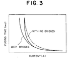
- bridges exhibit an effect that: a fuse element which has the bridges 4 is fused in a shorter time that a fuse element which had no bridges as shown in Figure 3 when they are subjected to a relatively low overcurrent though the fusing time remains as unchanged at relatively high overcurrents.
- the fuse element which has the bridges can be maintained at a higher current level than that of the fuse element which has no bridges and the same capacity as that of the fuse element having the bridges when no-fusing points of the two curves are coincided with each other as indicated by the two-dot chain line.
- a width and a length of the bridges can be selected according to the current region within which the slow-blow characteristic is to be obtained and the desired fusing time.
- the bridges have a width and a length which are comparable to the width of the slender element portion and preferably within twice the latter width.
- the portions of the fuse element according to the present invention described above are punched out of a single electrically conductive sheet 10 as shown in Figure 2 by using a press.
- the fuse element shown in Figure 1 is formed by tightly bending the wings 5 and 5 along the dashed lines shown in Figure 2, folding the female terminals 1A and 1B along the dashed lines into a prism-like form and finally bending the central portion of the slender element portion.
- the number of bends for the wings are not specifically limited but the wings may be bent threefold or fourfold.
- the fusing time is delayed, i.e. the fuse element is fused more slowly, by locating the bridges 4 provided for attaching the wings nearer the center of the element portion 2, but location of the bridges too close to the element portion 2 will pose a problem that the fuse element is not fused at the portion to be fused 3 located centrally between the element portions 2.
- Fuses generally have a transparent window provided in the center of the upper surface of the insulating housing to allow a visual check of the element portion. The visual check is no use if the fuse element is not fused at the portion to be fused 3 i.e. centrally between the element portions.
- the wide wings 5 and 5 are provided on both sides of the fusing element portion 3 by short narrow bridges 4.
- the distance measured from the center of the slender element portion 2 to the center of the bridge 4 lies within the range 1/6 to 1/4 of the total length of the element portion 2 and the wing 5 is configured to have volume of at least 5 mm 3 to provide the desired slow-blow characteristic and so that the fuse fails centrally on the element portion 2.
- Figure 4 is a graph showing influences on fuse performance due to the location of the wings 4, namely the relationship between fusing time at 200% overcurrent and the ratio of the distance from the center of the element portion 2 to the bridge 4 of the wing 5 relative to the total length of the element portion 2.
- the graph indicates a ratio of 0.26 for a fusing time of 5 seconds, which is the minimum within a range specified for fuses by JASO-D614 (5 to 100 seconds). It is necessary to located the bridge closer than this.
- the present invention uses a ratio not exceeding 1/4 (0.25) for affording a slight margin.
- a shorter distance it may be selected at any location on the graph.
- a ratio of not lower than 1/6 (0.17) is preferable since the fuse element may be fused at locations other than the fusing portion 3 below this value.
- Figure 5 shows influences on fuse performance due to volumes of the wings, namely the relationship between the fusing time for a 200% overcurrent and the volume of a wing.
- the graph indicates a volume of 4.5 mm 3 of the wing for 5 seconds which is the minimum within the range specified by JASO-D614. Therefore to meet the standard, the present invention provides a volume not less than 5 mm 3 , affording a slight margin.
- An upper limit for the wing volume is determined based on economical use of the material shown in Figure 2, balance after bending the spring portions and capacities of fuses. A value of approximately 10 mm 3 is chosen as an upper limit.
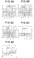
- FIGS. 6A, 6B, 6C, 6D and 6E Shown in Figures 6A, 6B, 6C, 6D and 6E are various arrangements for the bridges 4 and the wings 5 relative to the slender element portion 2. Dashed lines in the drawings indicate fold lines and a reference numeral 6 represents slits which are formed on the locations to be folded for facilitating folding and improving tightness of the wings, but are not always required.
- the fuse element it is preferable, as described above, to dispose the wings 5 symmetrically with regard to the center of the slender element portion 2 (the portion to be fused) in the longitudinal direction for proper heat transmission balance.
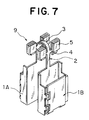
- Figure 7 is a perspective view showing a fuse element which is formed by bending the wings along the dashed lines shown in Figure 6A.
Abstract
Description
- The present invention relates to a fuse element for slow-blow fuses which are used mainly in vehicles for protecting load circuits from overcurrents.
- (1) Known slow-blow fuses typically have fuse elements as shown in Figure 8 wherein a thin sheet-
like element 2 is encapsulated, leaving aportion 3 to be fused, and fixed in anendothermic body 15 made of an inorganic material.Female terminals element 2. Theendothermic body 15 is accommodated in a space formed in a casing, and thefemale terminals
The slow-blow fused in the subject of Japanese Utility Model Application No. 1601984 (Utility Model Publication No. 59-41563). - (2) On the other hand, there is known a slow-blow fuse, shown in Figures 9A and 9B wherein portions to be fused 3 of a
fuse element 9 are formed integrally withheat accumulating portions 16 by using an electrically conductive metallic material. Electricallyconductive ends
The slow-blow fuse shown in Figure 9A, is an example which is obtained by press molding a flat sheet of copper so that a punched flat sheet has projectingheat accumulating portions 16. On the other hand the slow-blow fuse shown in Figure 9B is obtained by folding back the projecting portions shown in Figure 9A so as to form cubicheat accumulating portions 16 as disclosed in embodiments of Japanese Utility Model Publication No. 61-11258. - (3) Japanese Patent Application No. 7-6686 discloses punching out
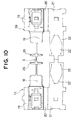
spring portions 22, which extend fromplates 21, along with a portion to be fused 3, approximately adjacent thereto. Economical use of materials is achieved by manufacturing a connecting terminal for fuses of this type by punching and shaping a pair of fuse connecting portions and the portion to be fused out of a single electrically conductive sheet. A pair of connectingportions spring portions 22 and abottom plate 18. The connectingportions side spring portion 22 which is folded so that it is surrounded by thebottom plates 18,side plates ceiling plates 21. The connecting portions are joined to each other by way of the portion to be fused 3 and heat dissipatingprotrusion portions 26, which are disposed on both sides of the portion to be fused 3 as shown in Figure 10. These members are to be punched out of an electrically conductive metal sheet and shaped. - (4) Japanese Patent Application No. 7-14494 discloses a fuse wherein a wrapping
portion 23 is disposed on ametallic fusible member 2 so as to wrap achip 24 made of a metal having a low fusion point. The fusible member is configured to have anarrow portion 25 having a small sectional area. Aheat dissipating plate 26 is disposed in the vicinity of thenarrow portion 25 as shown in Figure 11. - The slow-blow fuse mentioned in (1) above, in which the
element 2 and theendothermic body 15 made of inorganic material are produced as separate parts and require shaped grooves in the endothermic body and the element since these parts must be precisely coupled and cemented to each other. This requires advanced manufacturing technology since theelement 2 and theendothermic body 15 must be assembled with very high mechanical precision. Should the endothermic body not be fixed correctly to theelement 2, the slow-blow fuse will not provide the intended performance. - Accordingly, this slow-blow fuse is expensive to produce in terms of material cost and manufacturing cost.
- The slow-blow fuse mentioned in (2) above which is punched, as an integral member including the heat accumulating portions, out of a single flat copper sheet has not yet been put to practical use as far as the inventor knows. The
heat accumulating portions 16 are located very close to the portion to be fused. They require a large width on both sides thereof and exhibit too high a heat accumulating function, thereby disabling the portion to be fused under certain conditions or exhibit undesirable fusing characteristics. - The wrapping type
heat accumulating body 16 shown in Figure 9B is compact but is difficult and slow to manufacture, since tedious procedures are required for wrapping. - The connecting terminal for fuses mentioned in (4) above, in which the heat dissipating
protrusion portions wrapping portion 23, i.e. wrapping thechip 24 made of low fusion point metal in the heat dissipatingprotrusion portions 26 as shown in Figure 11. - Accordingly, the connecting terminal for fuses mentioned in (3) above is configured to permit economical manufacture of fuses by careful use of material therefore. In contrast, the fuse mentioned in (4) above is configured for the purpose of providing fuses which can be fused within a predetermined time for overcurrents in the high, medium or low regions.
- The slow-blow fuse according to the present invention attempts to overcome the problems posed by the various types of conventional fuses described above, while maintaining the merit of advantageous use of material provided by the terminal for fuses mentioned in (3) above.
- According to the present invention there is provided a fuse element for a slow-blow fuse, including a pair of terminals;
- a slender element portion connected to an end of each terminal, and a portion to be fused located centrally on the element portion; characterised in that
- at least one wing is formed on the element portion on each side of the central fusing portion, and
- said wings are connected to said slender element portion by short narrow bridges.
- A first fuse element for slow-blow fuses according to the present invention is punched out of a single electrically
conductive sheet 10. Aslender element portion 2 connects the ends of a pair ofterminals Wings 5 are connected by short narrow links or bridges to the element portions on both sides of a central portion to be fused 3. - Preferably the
bridges 4 are connected to theslender element portion 2 within a range of 1/6 to 1/4 of a total length of theelement portions 2, from the portion to be fused. - Further, the
wing 5 preferably has a volume of at least 5 mm3. Advantageously one or more parts of the wings are bent over double so that the bent part is brought into contact with another part of the same wing. This provides a more three dimensional cubic shape. This bending may be repeated more than once. - The
wings 5 are preferably arranged symmetrically with regard to a center of theelement portion 2. - A fuse element formed as described above, initially absorbs and accumulates heat in the wings during an overcurrent such that fusion of the
portion 3 located centrally on the element portion provide the desired slow-blow characteristic. - The characteristics of the slow-blow fuse can be easily adjusted by changing the location of the bridges or the volume of the wings.
- Further, the fuse element according to the present invention can be formed simply by punching out and bending a single electrically conductive sheet using a press, thereby making it possible to reduce material costs, enhance productivity and provide stable slow-blow characteristics.
- The present invention will be more clearly understood from the following description, given by way of example only, with reference to the accompanying drawings in which:
- Fig. 1 is a perspective view illustrating an embodiment of the fuse element according to the present invention;
- Fig. 2 is a development illustrating the fuse element shown in Figure 1 in a condition before it is formed;
- Fig. 3 is a graph illustrating the relationship between current and fusing time which varies dependent upon the use of the bridges;
- Fig. 4 is a graph illustrating influences on fuse performance due to the location of the bridges;
- Fig. 5 is a graph illustrating influences on fuse performance due to the volume of wings;
- each of Fig. 6A to 6E is a partial plan view illustrating various disposing modes for the bridges and the wings relative to the element portions according to the present invention;
- Fig. 7 is a perspective view illustrating another embodiment of the fuse element according to the present invention;
- Fig. 8 is a perspective view illustrating a conventional fuse element in a disassembled condition thereof;
- each of Figs. 9A and 9B is a partial perspective view illustrating another conventional fuse element;
- Fig. 10 is a development illustrating still another conventional fuse element in a condition before it is formed; and
- Fig. 11 is a partial perspective view illustrating further another conventional fuse element.
- Figure 1 is a perspective view of the
fuse element 9 for slow-blow fuses according to the present invention. This fuse element is formed by punching out a single electricallyconductive sheet 10 made of a copper alloy of Cu-Fe or Cu-Ni-Si. It comprises insideportions female terminals spring sheets outside portions slender element portion 2,bridges 4 andwings 5 which have an endothermic function. These parts are connected to one another as shown in Figure 2. The fuse element is then formed by bending thewings 5, forming thefemale terminals inside portions spring sheet portions outside portions element portion 2. - Figure 2 shows a development illustrating the fuse element in a condition before it is formed. In this drawing, the
reference numerals element portion 2, thereference numerals inside portions reference numerals spring sheet portions - The
spring sheet portions springs - In the drawing,
reference numeral 2 represents a slender element portion extending from each of theinside portions Wings narrow bridges 4. - These bridges exhibit an effect that: a fuse element which has the
bridges 4 is fused in a shorter time that a fuse element which had no bridges as shown in Figure 3 when they are subjected to a relatively low overcurrent though the fusing time remains as unchanged at relatively high overcurrents. - Accordingly, it will be understood that as a result of this slow-blow characteristic, the fuse element which has the bridges can be maintained at a higher current level than that of the fuse element which has no bridges and the same capacity as that of the fuse element having the bridges when no-fusing points of the two curves are coincided with each other as indicated by the two-dot chain line. A width and a length of the bridges can be selected according to the current region within which the slow-blow characteristic is to be obtained and the desired fusing time.
- It is desirable that the bridges have a width and a length which are comparable to the width of the slender element portion and preferably within twice the latter width.
- The portions of the fuse element according to the present invention described above are punched out of a single electrically
conductive sheet 10 as shown in Figure 2 by using a press. The fuse element shown in Figure 1 is formed by tightly bending thewings female terminals - The number of bends for the wings are not specifically limited but the wings may be bent threefold or fourfold.
- The fusing time is delayed, i.e. the fuse element is fused more slowly, by locating the
bridges 4 provided for attaching the wings nearer the center of theelement portion 2, but location of the bridges too close to theelement portion 2 will pose a problem that the fuse element is not fused at the portion to be fused 3 located centrally between theelement portions 2. - Fuses generally have a transparent window provided in the center of the upper surface of the insulating housing to allow a visual check of the element portion. The visual check is no use if the fuse element is not fused at the portion to be fused 3 i.e. centrally between the element portions.
- In the fuse element for slow-blow fuses according to the present invention, the
wide wings element portion 3 by shortnarrow bridges 4. The distance measured from the center of theslender element portion 2 to the center of thebridge 4 lies within therange 1/6 to 1/4 of the total length of theelement portion 2 and thewing 5 is configured to have volume of at least 5 mm3 to provide the desired slow-blow characteristic and so that the fuse fails centrally on theelement portion 2. - The numerical values set for the fuse element according to the present invention described above are selected for the reasons described below.
- Figure 4 is a graph showing influences on fuse performance due to the location of the
wings 4, namely the relationship between fusing time at 200% overcurrent and the ratio of the distance from the center of theelement portion 2 to thebridge 4 of thewing 5 relative to the total length of theelement portion 2. - The graph indicates a ratio of 0.26 for a fusing time of 5 seconds, which is the minimum within a range specified for fuses by JASO-D614 (5 to 100 seconds). It is necessary to located the bridge closer than this. The present invention uses a ratio not exceeding 1/4 (0.25) for affording a slight margin.
- As for a shorter distance, it may be selected at any location on the graph. A ratio of not lower than 1/6 (0.17) is preferable since the fuse element may be fused at locations other than the fusing
portion 3 below this value. - Figure 5 shows influences on fuse performance due to volumes of the wings, namely the relationship between the fusing time for a 200% overcurrent and the volume of a wing.
- The graph indicates a volume of 4.5 mm3 of the wing for 5 seconds which is the minimum within the range specified by JASO-D614. Therefore to meet the standard, the present invention provides a volume not less than 5 mm3, affording a slight margin.
- An upper limit for the wing volume is determined based on economical use of the material shown in Figure 2, balance after bending the spring portions and capacities of fuses. A value of approximately 10 mm3 is chosen as an upper limit.
- The data shown in the graphs of Figures 4 and 5 described above were obtained by carrying out experiments on fuse elements having a rating of 30A, i.e. fuse elements having an electrically
conductive sheet 10 which is 0.5 mm thick, anelement portion 2 which is 0.8 mm wide and has a total length of 40 mm, and bridges 4 which are 1 mm wide and 1 mm long. The conditions described above were specified on the basis of the experimental data obtained with a fuse element having a rating of 30A. Similar data was obtained by measurements effected at intervals of 10 A within a range of ratings from 10 A to 40A. - Various arrangements for the
wings 5 are conceivable for the fuse element according to the present invention. Arrangements for thebridges 4 and thewings 5 will be described below with reference to the accompanying drawings. - Shown in Figures 6A, 6B, 6C, 6D and 6E are various arrangements for the
bridges 4 and thewings 5 relative to theslender element portion 2. Dashed lines in the drawings indicate fold lines and areference numeral 6 represents slits which are formed on the locations to be folded for facilitating folding and improving tightness of the wings, but are not always required. - For the fuse element according to the present invention, it is preferable, as described above, to dispose the
wings 5 symmetrically with regard to the center of the slender element portion 2 (the portion to be fused) in the longitudinal direction for proper heat transmission balance. - Figure 7 is a perspective view showing a fuse element which is formed by bending the wings along the dashed lines shown in Figure 6A.
- While the present invention is described and shown with a single slender element member having a continuous cross-section with the portion to be fused located centrally thereon, it is also possible to provide the portion to be fused on a narrowed portion of the element member.
- Many widely different embodiments of the present invention may be constructed without departing from the scope of the present invention. It should be understood that the present invention is not limited to the specific embodiments described herein, except as defined in the appended claims.
Claims (9)
- A fuse element for a slow-blow fuse, including a pair of terminals (1A, 1B);a slender element portion (2) connected to an end of each terminal (1A, 1B), and a portion to be fused (3) located centrally on the element portion (2) ; characterised in thatat least one wing (5) is formed on the element portion (2) on each side of the central fusing portion (3), andsaid wings (5) are connected to said slender element portion (2) by short narrow bridges (4).
- A fuse element according to claim 1 punched out of a single electrically conductive sheet (10).
- A fuse element according to claim 1 or 2 wherein the distance from the portion to be fused to where the narrow bridges (4) are connected to said slender element portion (2) is in the range from 1/6 to 1/4 of the total length of said element portion (2).
- A fuse element according to any one of the preceding claims wherein the wings (5) are disposed symmetrically with regard to the portion to be fused (3).
- A fuse element according to any one of the preceding claims wherein one wing is formed on each side of the portion to be fused on the same side of the element portion.
- A fuse element according to any one of claims 1-4 wherein one wing is formed on each side of the portion to be fused on opposite sides of the element portion.
- A fuse element according to any one of claims 1 to 4, wherein, a pair of wings are formed on each side of the portions to be fused (3) on both sides of the element portion (2).
- A fuse element according to any one of the preceding claims, wherein each wing (5) has a volume of at least 5 mm3 and has a cubic form obtained by tightly bending the wings at least double.
- A fuse element according to claim 8, wherein said wings are provided with slits.
Applications Claiming Priority (3)
| Application Number | Priority Date | Filing Date | Title |
|---|---|---|---|
| JP27972395 | 1995-10-02 | ||
| JP27972395A JP3677569B2 (en) | 1995-10-02 | 1995-10-02 | Slow blow fuse fuse element |
| JP279723/95 | 1995-10-02 |
Publications (3)
| Publication Number | Publication Date |
|---|---|
| EP0767479A2 true EP0767479A2 (en) | 1997-04-09 |
| EP0767479A3 EP0767479A3 (en) | 1998-01-14 |
| EP0767479B1 EP0767479B1 (en) | 2001-03-14 |
Family
ID=17614987
Family Applications (1)
| Application Number | Title | Priority Date | Filing Date |
|---|---|---|---|
| EP96307126A Expired - Lifetime EP0767479B1 (en) | 1995-10-02 | 1996-09-27 | Fuse element for slow-blow fuses |
Country Status (6)
| Country | Link |
|---|---|
| US (1) | US5745024A (en) |
| EP (1) | EP0767479B1 (en) |
| JP (1) | JP3677569B2 (en) |
| KR (1) | KR100414009B1 (en) |
| CA (1) | CA2186821C (en) |
| DE (1) | DE69612054T2 (en) |
Families Citing this family (16)
| Publication number | Priority date | Publication date | Assignee | Title |
|---|---|---|---|---|
| JP2001076611A (en) * | 1999-09-06 | 2001-03-23 | Koa Corp | Circuit protective element |
| JP2001325875A (en) * | 2000-05-18 | 2001-11-22 | Yazaki Corp | Plug-in type fuse |
| JP4706613B2 (en) * | 2006-03-24 | 2011-06-22 | 住友電装株式会社 | Slow blow fuse fuse element, slow blow fuse and electrical junction box |
| US7595715B2 (en) * | 2007-09-27 | 2009-09-29 | Lear Corporation | High power case fuse |
| US8339235B2 (en) * | 2008-08-06 | 2012-12-25 | Beckert James J | Housing securing apparatus for electrical components, especially fuses |
| US20100060408A1 (en) * | 2008-09-09 | 2010-03-11 | Wen-Tsung Cheng | Fuse module with indicating capability |
| JP5681389B2 (en) * | 2009-06-10 | 2015-03-04 | 矢崎総業株式会社 | Fusible link |
| US8366497B2 (en) * | 2009-06-17 | 2013-02-05 | Lear Corporation | Power terminal |
| US7892050B2 (en) * | 2009-06-17 | 2011-02-22 | Lear Corporation | High power fuse terminal with scalability |
| US8951051B2 (en) | 2011-10-10 | 2015-02-10 | Lear Corporation | Connector having optimized tip |
| US9166322B2 (en) | 2013-02-08 | 2015-10-20 | Lear Corporation | Female electric terminal with gap between terminal beams |
| US9548553B2 (en) | 2013-03-15 | 2017-01-17 | Lear Corporation | Terminal with front end protection |
| US9190756B2 (en) | 2013-08-01 | 2015-11-17 | Lear Corporation | Electrical terminal assembly |
| US9142902B2 (en) | 2013-08-01 | 2015-09-22 | Lear Corporation | Electrical terminal assembly |
| US9711926B2 (en) * | 2013-11-19 | 2017-07-18 | Lear Corporation | Method of forming an interface for an electrical terminal |
| JP6314964B2 (en) * | 2015-12-03 | 2018-04-25 | トヨタ自動車株式会社 | connector |
Citations (5)
| Publication number | Priority date | Publication date | Assignee | Title |
|---|---|---|---|---|
| BE460202A (en) * | 1945-02-13 | |||
| DE497223C (en) * | 1926-09-05 | 1930-05-07 | Georg J Meyer Dr Ing | Fuse with closed fusible link for motor protection |
| WO1989003117A1 (en) * | 1987-09-30 | 1989-04-06 | Cooper Industries, Inc. | Cable fuse |
| EP0631294A2 (en) * | 1993-06-22 | 1994-12-28 | Yazaki Corporation | Fuse |
| EP0633592A1 (en) * | 1993-06-21 | 1995-01-11 | Yazaki Corporation | Connection terminal for fuse |
Family Cites Families (10)
| Publication number | Priority date | Publication date | Assignee | Title |
|---|---|---|---|---|
| JPS5941563A (en) * | 1982-09-02 | 1984-03-07 | 近畿工業株式会社 | Casting frame suitable for sash pre-attaching construction |
| JPS6111258A (en) * | 1984-06-27 | 1986-01-18 | Toshiba Corp | Wire dot printer |
| EP0228490A1 (en) * | 1985-12-24 | 1987-07-15 | Sumitomo Wiring Systems, Ltd. | Slow blow fuse |
| JPS62246219A (en) * | 1986-04-18 | 1987-10-27 | 矢崎総業株式会社 | Terminal with fuse |
| JPH0766734B2 (en) * | 1987-09-01 | 1995-07-19 | 矢崎総業株式会社 | Fuse manufacturing method |
| DE3909302A1 (en) * | 1988-03-23 | 1989-10-12 | Yazaki Corp | FUSE PROTECTION AND METHOD FOR PRODUCING THE SAME |
| US5373278A (en) * | 1991-01-16 | 1994-12-13 | Dav | Flat fuse for high rated currents |
| JP2624593B2 (en) * | 1991-12-12 | 1997-06-25 | 矢崎総業株式会社 | fuse |
| JP2552868Y2 (en) * | 1992-12-01 | 1997-10-29 | 矢崎総業株式会社 | Slow fuse |
| JP2745190B2 (en) * | 1993-08-27 | 1998-04-28 | 矢崎総業株式会社 | Slow fuse |
-
1995
- 1995-10-02 JP JP27972395A patent/JP3677569B2/en not_active Expired - Fee Related
-
1996
- 1996-09-26 US US08/721,330 patent/US5745024A/en not_active Expired - Fee Related
- 1996-09-27 EP EP96307126A patent/EP0767479B1/en not_active Expired - Lifetime
- 1996-09-27 DE DE69612054T patent/DE69612054T2/en not_active Expired - Fee Related
- 1996-09-30 CA CA002186821A patent/CA2186821C/en not_active Expired - Fee Related
- 1996-10-02 KR KR1019960043594A patent/KR100414009B1/en not_active IP Right Cessation
Patent Citations (5)
| Publication number | Priority date | Publication date | Assignee | Title |
|---|---|---|---|---|
| DE497223C (en) * | 1926-09-05 | 1930-05-07 | Georg J Meyer Dr Ing | Fuse with closed fusible link for motor protection |
| BE460202A (en) * | 1945-02-13 | |||
| WO1989003117A1 (en) * | 1987-09-30 | 1989-04-06 | Cooper Industries, Inc. | Cable fuse |
| EP0633592A1 (en) * | 1993-06-21 | 1995-01-11 | Yazaki Corporation | Connection terminal for fuse |
| EP0631294A2 (en) * | 1993-06-22 | 1994-12-28 | Yazaki Corporation | Fuse |
Also Published As
| Publication number | Publication date |
|---|---|
| JPH0997557A (en) | 1997-04-08 |
| KR100414009B1 (en) | 2004-04-13 |
| EP0767479B1 (en) | 2001-03-14 |
| DE69612054T2 (en) | 2001-09-13 |
| CA2186821A1 (en) | 1997-04-03 |
| CA2186821C (en) | 2000-03-21 |
| DE69612054D1 (en) | 2001-04-19 |
| US5745024A (en) | 1998-04-28 |
| EP0767479A3 (en) | 1998-01-14 |
| KR970023522A (en) | 1997-05-30 |
| JP3677569B2 (en) | 2005-08-03 |
Similar Documents
| Publication | Publication Date | Title |
|---|---|---|
| EP0767479B1 (en) | Fuse element for slow-blow fuses | |
| US5581225A (en) | One-piece female blade fuse with housing | |
| RU2198448C2 (en) | Fusible element of multiple-electrode type and fuse of multiple-electrode type (alternatives) | |
| CA1175871A (en) | Fuse assembly for a miniature plug-in fuse | |
| US6558198B2 (en) | Fuse device and fuse device connecting structure | |
| JP4104817B2 (en) | Blade type fuse | |
| JP2745188B2 (en) | Connection terminal for fuse | |
| JPH0644446B2 (en) | Plug-in fuse device | |
| US5945903A (en) | Resettable automotive circuit protection device with female terminals and PTC element | |
| US4434548A (en) | Method of manufacturing plug-in electrical fuses | |
| US5929740A (en) | One-piece female blade fuse with housing and improvements thereof | |
| US5802703A (en) | Method of forming a chain of fuse-links | |
| US5086285A (en) | Time-current characteristics variable chip fuse | |
| US4651119A (en) | Electric fuse heat dam element having stiffening ribs | |
| US5847635A (en) | Blade-type fuse element having a load portion | |
| JPH10283906A (en) | Circuit connector serving also as fuse | |
| JPS5848982B2 (en) | Fuse | |
| TW202133207A (en) | Current-limiting fuse | |
| US20230051371A1 (en) | Fuse and method for manufacturing fuse | |
| JPS6231466B2 (en) | ||
| JP3757298B2 (en) | Plug-in fuse female terminal | |
| JP2000030599A (en) | Multipolar fuse element | |
| JPS6245418Y2 (en) | ||
| KR930004698Y1 (en) | Subminiature fuse | |
| JPH0917323A (en) | Plug type fuse |
Legal Events
| Date | Code | Title | Description |
|---|---|---|---|
| PUAI | Public reference made under article 153(3) epc to a published international application that has entered the european phase |
Free format text: ORIGINAL CODE: 0009012 |
|
| AK | Designated contracting states |
Kind code of ref document: A2 Designated state(s): DE FR GB IT |
|
| PUAL | Search report despatched |
Free format text: ORIGINAL CODE: 0009013 |
|
| AK | Designated contracting states |
Kind code of ref document: A3 Designated state(s): DE FR GB IT |
|
| 17P | Request for examination filed |
Effective date: 19980707 |
|
| GRAG | Despatch of communication of intention to grant |
Free format text: ORIGINAL CODE: EPIDOS AGRA |
|
| 17Q | First examination report despatched |
Effective date: 20000523 |
|
| GRAG | Despatch of communication of intention to grant |
Free format text: ORIGINAL CODE: EPIDOS AGRA |
|
| GRAH | Despatch of communication of intention to grant a patent |
Free format text: ORIGINAL CODE: EPIDOS IGRA |
|
| GRAH | Despatch of communication of intention to grant a patent |
Free format text: ORIGINAL CODE: EPIDOS IGRA |
|
| RAP1 | Party data changed (applicant data changed or rights of an application transferred) |
Owner name: PACIFIC ENGINEERING CORPORATION |
|
| GRAA | (expected) grant |
Free format text: ORIGINAL CODE: 0009210 |
|
| AK | Designated contracting states |
Kind code of ref document: B1 Designated state(s): DE FR GB IT |
|
| REF | Corresponds to: |
Ref document number: 69612054 Country of ref document: DE Date of ref document: 20010419 |
|
| ITF | It: translation for a ep patent filed |
Owner name: ING. A. GIAMBROCONO & C. S.R.L. |
|
| ET | Fr: translation filed | ||
| REG | Reference to a national code |
Ref country code: GB Ref legal event code: IF02 |
|
| PLBE | No opposition filed within time limit |
Free format text: ORIGINAL CODE: 0009261 |
|
| STAA | Information on the status of an ep patent application or granted ep patent |
Free format text: STATUS: NO OPPOSITION FILED WITHIN TIME LIMIT |
|
| 26N | No opposition filed | ||
| PGFP | Annual fee paid to national office [announced via postgrant information from national office to epo] |
Ref country code: IT Payment date: 20080926 Year of fee payment: 13 Ref country code: FR Payment date: 20080915 Year of fee payment: 13 |
|
| PGFP | Annual fee paid to national office [announced via postgrant information from national office to epo] |
Ref country code: DE Payment date: 20081002 Year of fee payment: 13 |
|
| PGFP | Annual fee paid to national office [announced via postgrant information from national office to epo] |
Ref country code: GB Payment date: 20081001 Year of fee payment: 13 |
|
| GBPC | Gb: european patent ceased through non-payment of renewal fee |
Effective date: 20090927 |
|
| REG | Reference to a national code |
Ref country code: FR Ref legal event code: ST Effective date: 20100531 |
|
| PG25 | Lapsed in a contracting state [announced via postgrant information from national office to epo] |
Ref country code: FR Free format text: LAPSE BECAUSE OF NON-PAYMENT OF DUE FEES Effective date: 20090930 Ref country code: DE Free format text: LAPSE BECAUSE OF NON-PAYMENT OF DUE FEES Effective date: 20100401 |
|
| PG25 | Lapsed in a contracting state [announced via postgrant information from national office to epo] |
Ref country code: GB Free format text: LAPSE BECAUSE OF NON-PAYMENT OF DUE FEES Effective date: 20090927 |
|
| PG25 | Lapsed in a contracting state [announced via postgrant information from national office to epo] |
Ref country code: IT Free format text: LAPSE BECAUSE OF NON-PAYMENT OF DUE FEES Effective date: 20090927 |