EP0767324B1 - Method for influencing the tension in a drive belt - Google Patents
Method for influencing the tension in a drive belt Download PDFInfo
- Publication number
- EP0767324B1 EP0767324B1 EP96202702A EP96202702A EP0767324B1 EP 0767324 B1 EP0767324 B1 EP 0767324B1 EP 96202702 A EP96202702 A EP 96202702A EP 96202702 A EP96202702 A EP 96202702A EP 0767324 B1 EP0767324 B1 EP 0767324B1
- Authority
- EP
- European Patent Office
- Prior art keywords
- speed
- drive belt
- transmission
- belt
- pulley
- Prior art date
- Legal status (The legal status is an assumption and is not a legal conclusion. Google has not performed a legal analysis and makes no representation as to the accuracy of the status listed.)
- Expired - Lifetime
Links
- 238000000034 method Methods 0.000 title claims description 19
- 230000005540 biological transmission Effects 0.000 claims description 73
- 230000001133 acceleration Effects 0.000 description 4
- 230000002411 adverse Effects 0.000 description 2
- 238000010276 construction Methods 0.000 description 2
- 230000001419 dependent effect Effects 0.000 description 2
- 238000011161 development Methods 0.000 description 1
- 230000018109 developmental process Effects 0.000 description 1
- 230000002035 prolonged effect Effects 0.000 description 1
- 238000000926 separation method Methods 0.000 description 1
Images



Classifications
-
- F—MECHANICAL ENGINEERING; LIGHTING; HEATING; WEAPONS; BLASTING
- F16—ENGINEERING ELEMENTS AND UNITS; GENERAL MEASURES FOR PRODUCING AND MAINTAINING EFFECTIVE FUNCTIONING OF MACHINES OR INSTALLATIONS; THERMAL INSULATION IN GENERAL
- F16H—GEARING
- F16H37/00—Combinations of mechanical gearings, not provided for in groups F16H1/00 - F16H35/00
- F16H37/02—Combinations of mechanical gearings, not provided for in groups F16H1/00 - F16H35/00 comprising essentially only toothed or friction gearings
- F16H37/021—Combinations of mechanical gearings, not provided for in groups F16H1/00 - F16H35/00 comprising essentially only toothed or friction gearings toothed gearing combined with continuously variable friction gearing
-
- F—MECHANICAL ENGINEERING; LIGHTING; HEATING; WEAPONS; BLASTING
- F16—ENGINEERING ELEMENTS AND UNITS; GENERAL MEASURES FOR PRODUCING AND MAINTAINING EFFECTIVE FUNCTIONING OF MACHINES OR INSTALLATIONS; THERMAL INSULATION IN GENERAL
- F16H—GEARING
- F16H61/00—Control functions within control units of change-speed- or reversing-gearings for conveying rotary motion ; Control of exclusively fluid gearing, friction gearing, gearings with endless flexible members or other particular types of gearing
- F16H61/66—Control functions within control units of change-speed- or reversing-gearings for conveying rotary motion ; Control of exclusively fluid gearing, friction gearing, gearings with endless flexible members or other particular types of gearing specially adapted for continuously variable gearings
- F16H61/662—Control functions within control units of change-speed- or reversing-gearings for conveying rotary motion ; Control of exclusively fluid gearing, friction gearing, gearings with endless flexible members or other particular types of gearing specially adapted for continuously variable gearings with endless flexible members
- F16H61/66272—Control functions within control units of change-speed- or reversing-gearings for conveying rotary motion ; Control of exclusively fluid gearing, friction gearing, gearings with endless flexible members or other particular types of gearing specially adapted for continuously variable gearings with endless flexible members characterised by means for controlling the torque transmitting capability of the gearing
Definitions
- the invention relates to a method for influencing the tension in a drive belt in a continuously variable transmission.
- a continuously variable transmission with drive belt is disclosed, for example, in European Patent EP 0 436 974 and is used in motor vehicles in particular.
- a continuously variable transmission of this type essentially comprises two pulleys and a drive belt arranged between the pulleys. Each pulley has two discs, the drive belt being accommodated in a slit between the discs.
- the aim of the invention is to overcome the abovementioned drawbacks by optimum loading of the drive belt, to provide a high power density, high efficiency and a wide control range.
- the method according to the invention is characterised in that the tension in the drive belt is determined as a function of the speed of the drive belt and in that, for part, parts or the entire range of the possible input speeds of the transmission, the input speed of the transmission is increased and/or reduced to a desired speed range for the drive belt with an essentially relatively lower tension in the drive belt.
- the power can be transmitted by the drive belt even in the case of adverse input speeds without the tensions in the drive belt becoming unacceptedly high and without the transmission and the drive belt having to be of heavy-duty construction.
- the compactness, the power density, the efficiency and the control range are improved as a result.
- the input speed of the transmission is reduced or increased to the desired speed of the drive belt and, for part, parts or the entire range of the possible speeds of the drive belt, the speed of the drive belt is increased or reduced to the desired output speed of the transmission.
- the reduction or increase in the input speed to the desired speed of the drive belt is at least partially corrected by increasing or, respectively, reducing the speed of the drive belt again to the output speed of the transmission.
- the part, parts or the entire range of the input speed for which the speed is reduced or increased adjoins the part, parts or the entire range for which the speed of the drive belt is increased or reduced to the output speed.
- the factor for increasing the input speed of the transmission is preferably between 1.1 and 3.5, whilst the factor for reducing the input speed of the transmission preferably has a value of between 0.35 and 0.9.
- the input speed of the transmission can be adjustable as a function of the transmission ratio of the transmission.
- the invention also relates to a continuously variable transmission which can be operated in accordance with the method described.
- the continuously variable transmission 1 shown diagrammatically in Figure 1 is connected by means of an input shaft 5 to the output shaft 2 of a drive unit 3.
- the transmission 1 comprises two pulleys 6 and 9, which have discs 7, 8 and 10, 11, respectively, which are mounted on the input shaft 5 and, respectively, the output shaft 12.
- the discs 7 and 11 are axially movable, so that the radial position of the drive belt 13, located between the pulleys 6 and 9, and thus the transmission ratio of the transmission can be varied.
- Figure 2A shows a graphical representation of the load curve in which, for constant power, the tension S in the drive belt 13 is plotted on a the vertical axis as a function of the speed N in of the input shaft 5.
- Three load curves are shown for different transmission ratios. The transmission ratio with the lowest value (the highest acceleration) results in curve A, whilst curve C is obtained with an average transmission ratio. All curves have an intermediate region I of relatively low tensions and fringe regions II and III of relatively high tensions. In fringe region II the tension is determined in particular by the torque to be transmitted, whilst in fringe region III the tension is determined in particular by the centrifugal action on the belt.
- the degree to which the drive belt 13 is driven into the fringe regions II and III is partly dependent on the conditions under which the transmission is used, for example whether or not a motor vehicle is driven fast and/or accelerated fast, as well as on the nature of the drive unit 3.
- a motor vehicle is driven fast and/or accelerated fast
- region III will predominate.
- the fringe regions II and III delimit the compactness, the power density, the efficiency and the control range of the drive belt and the transmission.
- Figure 2B shows a variogram of a continuously variable transmission according to the prior art.
- the lines 30, 31, 32 and 33 enclose a field 34 with all possible combinations of the output speeds N out , plotted on the vertical axis, and the input speeds N in , plotted on the horizontal axis.
- the input speed N in is a measure for the engine speed
- the output speed N out is a measure for the speed of the motor vehicle.
- the transmission ratio of the continuously variable transmission is determined by the ratio between the input speed N in and the output speed N out at a given point in time, as is indicated, for example, in Figure 2B by the working point 35. Within the field 34, the transmission ratio can be adjusted to an infinite number of values.
- Line 31 indicates the limit of the maximum permitted output speed N out for the various transmission ratios, whilst line 32 gives the limit for the maximum permitted input speed N in for different transmission ratios.
- the location of line 32 in the variogram is determined by the maximum permitted speed of the engine, whilst the maximum speed of the vehicle determines the location of line 31.
- the transmission ratio which is given by line 36, represents the transmission ratios at which the motor vehicle can achieve the maximum vehicle speed V max with the limited maximum input speed N in, max .
- This working point of maximum primary speed and maximum vehicle speed is indicated by the reference numeral (37).
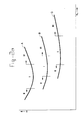
- FIG. 3A again shows that the tensions in the drive belt 13 have been determined, this time as a function of the speed N belt of the drive belt 13.
- the speed N belt of the drive belt has been separated from the input speed N in of the transmission.
- the separation has taken place in particular for the sub-regions X-X 1 and Y-Y 1 .
- the input speed N in has been increased to the higher speed range N belt1 -N belt2 of the drive belt.
- the input speed N in has been reduced to the lower speed range N belt3 - N belt4 .
- the input speed N in can be increased or reduced over the entire range, by which means an essentially relatively lower tension in the drive belt is likewise obtained.
- the input speed N in in combination with a low-revving diesel engine as the drive element 3, good results are obtained if the input speed N in is increased over the entire range.
- a high-revving engine as drive element 3 an advantageous result can once again be obtained according to the invention by reducing the input speed N in over the entire range. In all. cases the result is that the transmission acquires a higher power density and better efficiency as well as a wider control range and often can be more compact.
- the various features can be achieved in practice by, for example, using an accelerating and/or decelerating step, for example by incorporating a gear wheel group in the transmission in the drive direction before the pulley 6, 9/drive belt 13 combination.
- Said accelerating or decelerating steps are preferably adjustable.
- the acceleration or deceleration of the input speed N in of the transmission can also be obtained by controlling this with the output speed of the drive element 3.
- the tension in the drive belt 13 is partly dependent on the transmission ratio A, B and C at that point in time. Therefore, according to the invention, the increase or reduction in the input speed of the transmission can be adjusted as a function of the transmission ratio of the transmission.
- Figure 4 shows a variogram which largely corresponds to that in Figure 2B.
- an accelerating step has been inserted between the input: shaft 5 of the transmission 1 and the pulley 6.
- This has, for example, the result that the input speed N in1 of the transmission is translated into a speed N prim1 of pulley 6, which speed is a measure for the speed of the drive belt.
- N prim1 of pulley 6 which speed is a measure for the speed of the drive belt.
- N sec1 of the secondary pulley 9 results in a speed N sec1 of the secondary pulley 9.
- the speed N in1 would have resulted in an output speed of the transmission with a magnitude of N out1 .
- this speed would therefore be a speed of the magnitude of N sec1 .
- the transmission 1 So as not to influence the functioning of the transmission 1 as a whole by the use of the method of the invention, it can, according to the invention, be desirable to employ a decelerating step, for example once again a gear wheel step, after the pulley 9, which decelerating step reduces the speed N sec1 back to the output speed N out1 which would have been obtained without the use of the method according to the invention.
- a decelerating step for example once again a gear wheel step, after the pulley 9, which decelerating step reduces the speed N sec1 back to the output speed N out1 which would have been obtained without the use of the method according to the invention.
- the accelerating and, respectively, decelerating (sub-) ranges of the input speed of the transmission link up with the decelerating and, respectively, accelerating (sub-)ranges of the output speed.
Landscapes
- Engineering & Computer Science (AREA)
- General Engineering & Computer Science (AREA)
- Mechanical Engineering (AREA)
- Control Of Transmission Device (AREA)
- Transmissions By Endless Flexible Members (AREA)
- Devices For Conveying Motion By Means Of Endless Flexible Members (AREA)
- Transmission Devices (AREA)
Description
- The invention relates to a method for influencing the tension in a drive belt in a continuously variable transmission.
- Such a continuously variable transmission with drive belt is disclosed, for example, in European Patent EP 0 436 974 and is used in motor vehicles in particular. A continuously variable transmission of this type essentially comprises two pulleys and a drive belt arranged between the pulleys. Each pulley has two discs, the drive belt being accommodated in a slit between the discs. By changing the radial position of the drive belt between the pulleys, an infinite number of transmission ratios can be obtained within a certain control range. The radial position of the drive belt in the pulleys can be changed in that at least one disc of each pulley is axially movable.
- It is known from European Patent 0 436 974 that, when a torque converter is used, a temporary increase in the tension of the drive belt to above a certain fatigue value is acceptable when driving away the motor vehicle. However, the tension in the drive belt cannot be increased to above the fatigue value, and certainly not to above the breaking point, over the entire range of input speeds of the transmission and for a prolonged period. The transmission and drive belt must therefore also be of sufficiently heavy-duty construction to be able to transmit the full power even in the case of the most adverse input speeds of the transmission. The compactness, the power density, the efficiency and the control range are limited as a result.
- The aim of the invention is to overcome the abovementioned drawbacks by optimum loading of the drive belt, to provide a high power density, high efficiency and a wide control range.
- The method according to the invention is characterised in that the tension in the drive belt is determined as a function of the speed of the drive belt and in that, for part, parts or the entire range of the possible input speeds of the transmission, the input speed of the transmission is increased and/or reduced to a desired speed range for the drive belt with an essentially relatively lower tension in the drive belt. In this way the power can be transmitted by the drive belt even in the case of adverse input speeds without the tensions in the drive belt becoming unacceptedly high and without the transmission and the drive belt having to be of heavy-duty construction. The compactness, the power density, the efficiency and the control range are improved as a result.
- According to further developments of the invention, the input speed of the transmission is reduced or increased to the desired speed of the drive belt and, for part, parts or the entire range of the possible speeds of the drive belt, the speed of the drive belt is increased or reduced to the desired output speed of the transmission. What is achieved in this way is that the reduction or increase in the input speed to the desired speed of the drive belt is at least partially corrected by increasing or, respectively, reducing the speed of the drive belt again to the output speed of the transmission. According to the invention the part, parts or the entire range of the input speed for which the speed is reduced or increased adjoins the part, parts or the entire range for which the speed of the drive belt is increased or reduced to the output speed. In this way, although the tensions in the drive belt are limited, the relationship between the input and output speeds of the transmission remains unchanged, certainly if the same factor is used for the input speed and for the speed of the drive belt. The factor for increasing the input speed of the transmission is preferably between 1.1 and 3.5, whilst the factor for reducing the input speed of the transmission preferably has a value of between 0.35 and 0.9.
- According to the invention the input speed of the transmission can be adjustable as a function of the transmission ratio of the transmission.
- The invention also relates to a continuously variable transmission which can be operated in accordance with the method described.
- The invention will be explained with reference to a drawing. In the drawing:
- Figure 1
- shows, diagrammatically, a continuously variable transmission according to the prior art;
- Figure 2A
- shows tension curves for a drive belt as a function of the speed;
- Figure 2B
- shows a variogram of a transmission according to the prior art;
- Figure 3A
- shows tension curves for a drive belt operated in accordance with the method according to the invention;
- Figure 3B
- shows tension curves for a drive belt operated in accordance with the method according to the invention, as a function of the speed; and
- Figure 4
- shows a variogram of a continuously variable transmission operated in accordance with the method according to the invention.
- The continuously
variable transmission 1 shown diagrammatically in Figure 1 is connected by means of an input shaft 5 to theoutput shaft 2 of adrive unit 3. Thetransmission 1 comprises twopulleys 6 and 9, which havediscs discs 7 and 11 are axially movable, so that the radial position of thedrive belt 13, located between thepulleys 6 and 9, and thus the transmission ratio of the transmission can be varied. - Figure 2A shows a graphical representation of the load curve in which, for constant power, the tension S in the
drive belt 13 is plotted on a the vertical axis as a function of the speed Nin of the input shaft 5. Three load curves are shown for different transmission ratios. The transmission ratio with the lowest value (the highest acceleration) results in curve A, whilst curve C is obtained with an average transmission ratio. All curves have an intermediate region I of relatively low tensions and fringe regions II and III of relatively high tensions. In fringe region II the tension is determined in particular by the torque to be transmitted, whilst in fringe region III the tension is determined in particular by the centrifugal action on the belt. The degree to which thedrive belt 13 is driven into the fringe regions II and III is partly dependent on the conditions under which the transmission is used, for example whether or not a motor vehicle is driven fast and/or accelerated fast, as well as on the nature of thedrive unit 3. For a diesel engine the low-speed region II will predominate, whilst for a high-revving petrol engine, region III will predominate. Because the fatigue strength and the breaking strength of the belt may, in principle, not be exceeded, the fringe regions II and III delimit the compactness, the power density, the efficiency and the control range of the drive belt and the transmission. - Figure 2B shows a variogram of a continuously variable transmission according to the prior art. The
lines field 34 with all possible combinations of the output speeds Nout, plotted on the vertical axis, and the input speeds Nin, plotted on the horizontal axis. The input speed Nin is a measure for the engine speed, whilst the output speed Nout is a measure for the speed of the motor vehicle. The transmission ratio of the continuously variable transmission is determined by the ratio between the input speed Nin and the output speed Nout at a given point in time, as is indicated, for example, in Figure 2B by theworking point 35. Within thefield 34, the transmission ratio can be adjusted to an infinite number of values. -
Line 30 gives the lowest transmission ratio (= the highest acceleration) andline 33 the highest transmission ratio (= the lowest acceleration).Line 31 indicates the limit of the maximum permitted output speed Nout for the various transmission ratios, whilstline 32 gives the limit for the maximum permitted input speed Nin for different transmission ratios. - Frequently the location of
line 32 in the variogram is determined by the maximum permitted speed of the engine, whilst the maximum speed of the vehicle determines the location ofline 31. - The transmission ratio, which is given by
line 36, represents the transmission ratios at which the motor vehicle can achieve the maximum vehicle speed Vmax with the limited maximum input speed Nin, max. This working point of maximum primary speed and maximum vehicle speed is indicated by the reference numeral (37). - Figure 3A again shows that the tensions in the
drive belt 13 have been determined, this time as a function of the speed Nbelt of thedrive belt 13. Here the speed Nbelt of the drive belt has been separated from the input speed Nin of the transmission. In this case the separation has taken place in particular for the sub-regions X-X1 and Y-Y1. For the sub-region X-X1 the input speed Nin has been increased to the higher speed range Nbelt1-Nbelt2 of the drive belt. For the sub-region Y-Y1 the input speed Nin has been reduced to the lower speed range Nbelt3 - Nbelt4. It will be clear that as a result of this method thedrive belt 13 is driven over a narrower speed range Nbelt with an essentially relatively lower tension in the drive belt. - Incidentally, it is not necessary according to the invention to increase or to reduce the input speed Nin of the transmission for multiple sub-regions. Thus, depending on the specific application conditions, the input speed Nin can be increased or reduced over the entire range, by which means an essentially relatively lower tension in the drive belt is likewise obtained. For example, in combination with a low-revving diesel engine as the
drive element 3, good results are obtained if the input speed Nin is increased over the entire range. On the other hand, in combination with a high-revving engine asdrive element 3, an advantageous result can once again be obtained according to the invention by reducing the input speed Nin over the entire range. In all. cases the result is that the transmission acquires a higher power density and better efficiency as well as a wider control range and often can be more compact. - Particularly suitable factors by which to increase the input speed have been found to lie between 1.1 and 3.5, whilst for a reduction in speed the factor lies between 0.35 and 0.9.
- Incidentally, the various features can be achieved in practice by, for example, using an accelerating and/or decelerating step, for example by incorporating a gear wheel group in the transmission in the drive direction before the
pulley 6, 9/drive belt 13 combination. Said accelerating or decelerating steps are preferably adjustable. The acceleration or deceleration of the input speed Nin of the transmission can also be obtained by controlling this with the output speed of thedrive element 3. As is indicated in Figure 3A, the tension in thedrive belt 13 is partly dependent on the transmission ratio A, B and C at that point in time. Therefore, according to the invention, the increase or reduction in the input speed of the transmission can be adjusted as a function of the transmission ratio of the transmission. This is shown in Figure 3B for the transmission ratio B for which regions Z-Z1 and Z11-Z111, respectively, of the input speed Nin are, respectively, increased and reduced. It will be clear that, for adjustment as a function of the transmission ratio, these sub-ranges are in a different location for, for example, transmission ratio A from Figure 3A than for transmission ratio B. - Figure 4 shows a variogram which largely corresponds to that in Figure 2B. In this case, however, an accelerating step has been inserted between the input: shaft 5 of the
transmission 1 and the pulley 6. This has, for example, the result that the input speed Nin1 of the transmission is translated into a speed Nprim1 of pulley 6, which speed is a measure for the speed of the drive belt. This, in turn, results in a speed Nsec1 of thesecondary pulley 9. Without the accelerating step, the speed Nin1 would have resulted in an output speed of the transmission with a magnitude of Nout1. With the accelerating step, this speed would therefore be a speed of the magnitude of Nsec1. So as not to influence the functioning of thetransmission 1 as a whole by the use of the method of the invention, it can, according to the invention, be desirable to employ a decelerating step, for example once again a gear wheel step, after thepulley 9, which decelerating step reduces the speed Nsec1 back to the output speed Nout1 which would have been obtained without the use of the method according to the invention. In the case of a reduction in the speed at the input of the transmission, it can, of course, be desirable to increase the speed again at the output. Preferably, the accelerating and, respectively, decelerating (sub-)ranges of the input speed of the transmission link up with the decelerating and, respectively, accelerating (sub-)ranges of the output speed. In this way, although the tensions in the drive belt are reduced no difference is found at the input and output of the transmission compared with those for a conventionally driven continuously variable transmission. Because of the correlation between torque and speed of the transmission, it is specified here that within the inventive concept and within the scope of protection torque can also be read in place of speed.
Claims (9)
- Method for influencing the tension (S) in a drive belt (13) of a continuously variable transmission (1) having an input shaft (5) capable of rotating at an input speed (Nin) and connected with a first pulley (6) and an output shaft (12) capable of rotating at an output speed (Nout) and connected with a second pulley (9), characterised in that, the tension (S) in the drive belt (13) is determined as a function of the speed of the drive belt (Nbelt), for constant power and in that for part, parts or the entire range of possible input speeds of the transmission (1) the speed of the drive belt (Nbelt) is increased or reduced to a desired speed range by increasing or reducing the speed of the first pulley (6) with respect to the input speed (Min), to lower the tension (S) in the drive belt (13).
- Method according to claim 1, characterised in that the speed of the drive belt (Nbelt) is reduced to the desired speed of the drive belt, by reducing the speed of the first pulley (6) with respect to the input speed (Nin), and in that for part, parts or the entire range of the possible speeds of the drive belt (Nbelt), the speed of the output shaft (Nout) is increased to the desired output speed of the transmission with respect to the speed of the second pulley (9).
- Method according to claim 1, characterised in that the speed of the drive belt (Nbelt) is increased to the desired speed of the drive belt, by increasing the speed of the first pulley (6) with respect to the input speed (Nin), and in that for part, parts or the entire range of the possible speeds of the drive belt (Nbelt), the speed of the output shaft (Nout) is reduced to the desired output speed of the transmission with respect to the speed of the second pulley (9).
- Method according to one of the preceding claims, characterised in that for the part, parts or the entire range of possible input speeds (Nin) of the transmission (1) for which the speed of the drive belt (Nbelt) has been increased or reduced to the desired speed of the drive belt, by increasing or reducing the speed of the first pulley (6) with respect to the input speed (Nin), the speed of the output shaft (Nout) is reduced or, respectively, increased to the desired output speed of with respect to the speed of the second pulley (9).
- Method according to one of the claims 2, 3 or 4, characterised in that the reduction or increase of the speed of the drive belt (Nbelt) to a desired speed range by increasing or reducing the speed of the first pulley (6) with respect to the input speed (Nin) and the subsequent increase or, respectively reduction of the speed of the output shaft (Nout) to the desired output speed of the transmission with respect to the speed of the second pulley (9) takes place by an approximately equal factor.
- Method according to claim 5, characterised in that the increase of the speed of the drive belt (Nbelt) to a desired speed range by reducing the speed of the first pulley (6) with respect to the input speed (Nin) preferably takes place by a factor between 1.1 and 3.5.
- Method according to claim 5, characterised in that the reduction of the speed of the drive belt (Nbelt) to a desired speed range by increasing the speed of the first pulley (6) with respect to the input speed (Nin) preferably takes place by a factor between 0.35 and 0.9.
- Method according to one of the claims 2, 3 or 4, characterised in that the reduction or increase of the speed of the drive belt (Nbelt) to a desired speed range by increasing or reducing the speed of the first pulley (6) with respect to the input speed (Nin) is adjusted as a function of the transmission ratio of the transmission (1).
- Continuously variable transmission (1) which can be operated in accordance with the method of one of the preceding claims.
Applications Claiming Priority (2)
| Application Number | Priority Date | Filing Date | Title |
|---|---|---|---|
| NL1001345 | 1995-10-05 | ||
| NL1001345A NL1001345C2 (en) | 1995-10-05 | 1995-10-05 | Method for influencing the tension in a drive belt. |
Publications (2)
| Publication Number | Publication Date |
|---|---|
| EP0767324A1 EP0767324A1 (en) | 1997-04-09 |
| EP0767324B1 true EP0767324B1 (en) | 2001-09-05 |
Family
ID=19761665
Family Applications (1)
| Application Number | Title | Priority Date | Filing Date |
|---|---|---|---|
| EP96202702A Expired - Lifetime EP0767324B1 (en) | 1995-10-05 | 1996-09-26 | Method for influencing the tension in a drive belt |
Country Status (5)
| Country | Link |
|---|---|
| US (1) | US5683318A (en) |
| EP (1) | EP0767324B1 (en) |
| JP (2) | JP4181230B2 (en) |
| DE (1) | DE69614956T2 (en) |
| NL (1) | NL1001345C2 (en) |
Families Citing this family (6)
| Publication number | Priority date | Publication date | Assignee | Title |
|---|---|---|---|---|
| US6099424A (en) * | 1998-12-30 | 2000-08-08 | Hamilton Sundstrand Corporation | Continuously variable transmission with control arrangement and method for recovering from transmission belt slipping |
| DE60102030T2 (en) | 2000-05-03 | 2004-12-02 | Van Doorne's Transmissie B.V. | Infinitely variable transmission with a variable gear ratio coverage |
| EP1152171B1 (en) * | 2000-05-03 | 2004-02-18 | Van Doorne's Transmissie B.V. | A continuously variable transmission having a variable transmission ratio coverage |
| US8585413B2 (en) * | 2011-05-18 | 2013-11-19 | Sandia Corporation | Rotary electrical contact device and method for providing current to and/or from a rotating member |
| US10971876B1 (en) * | 2019-05-23 | 2021-04-06 | National Technology & Engineering Solutions Of Sandia, Llc | Belt structures for rotary electrical contact device |
| US11031744B1 (en) * | 2019-05-23 | 2021-06-08 | National Technology & Engineering Solutions Of Sandia, Llc | Belt structures for rotary electrical contact device |
Family Cites Families (10)
| Publication number | Priority date | Publication date | Assignee | Title |
|---|---|---|---|---|
| EP0004412A1 (en) * | 1978-01-21 | 1979-10-03 | GKN Transmissions Limited | Continuously variable transmission mechanisms |
| US4458318A (en) * | 1981-04-24 | 1984-07-03 | Borg-Warner Corporation | Control arrangement for a variable pulley transmission |
| NL8200564A (en) * | 1982-02-15 | 1983-01-03 | Doornes Transmissie Bv | TRANSMISSION, ESPECIALLY FOR A MOTOR VEHICLE. |
| NL8205048A (en) * | 1982-12-30 | 1984-07-16 | Doornes Transmissie Bv | Steplessly variable vehicle e.g. motorcycle transmission - has gearwheel on input shaft meshing with internally-toothed one on primary shaft |
| EP0157050A1 (en) * | 1983-12-23 | 1985-10-09 | Borg-Warner Corporation | Multi-pass continuously variable transmission |
| JPH0621639B2 (en) * | 1985-03-26 | 1994-03-23 | トヨタ自動車株式会社 | Hydraulic control system for belt type continuously variable transmission |
| US4718308A (en) * | 1985-03-29 | 1988-01-12 | Borg-Warner Automotive, Inc. | Hydraulic control system for continuously variable transmission |
| US4731044A (en) * | 1985-12-18 | 1988-03-15 | Borg-Warner Automotive, Inc. | Tension sensor and control arrangement for a continuously variable transmission |
| JP2661346B2 (en) * | 1989-09-18 | 1997-10-08 | トヨタ自動車株式会社 | Hydraulic control device for continuously variable transmission for vehicles |
| NL9000075A (en) * | 1990-01-11 | 1991-08-01 | Doornes Transmissie Bv | METHOD FOR CONTROLLING THE VOLTAGE IN A CONTINUOUSLY VARIABLE TRANSMISSION. |
-
1995
- 1995-10-05 NL NL1001345A patent/NL1001345C2/en not_active IP Right Cessation
-
1996
- 1996-09-26 DE DE69614956T patent/DE69614956T2/en not_active Expired - Fee Related
- 1996-09-26 EP EP96202702A patent/EP0767324B1/en not_active Expired - Lifetime
- 1996-09-27 US US08/723,984 patent/US5683318A/en not_active Expired - Lifetime
- 1996-10-07 JP JP26566696A patent/JP4181230B2/en not_active Expired - Lifetime
-
2005
- 2005-10-06 JP JP2005293131A patent/JP2006071106A/en active Pending
Also Published As
| Publication number | Publication date |
|---|---|
| JP4181230B2 (en) | 2008-11-12 |
| NL1001345C2 (en) | 1997-04-08 |
| DE69614956D1 (en) | 2001-10-11 |
| DE69614956T2 (en) | 2002-04-11 |
| JPH09158999A (en) | 1997-06-17 |
| US5683318A (en) | 1997-11-04 |
| JP2006071106A (en) | 2006-03-16 |
| EP0767324A1 (en) | 1997-04-09 |
Similar Documents
| Publication | Publication Date | Title |
|---|---|---|
| EP1529988B1 (en) | Control apparatus for continuously variable transmission of vehicle | |
| KR100644735B1 (en) | Transmission ratio control device of continuously variable transmission and its method | |
| US4658360A (en) | Method and apparatus for controlling continuously variable transmission for vehicle | |
| EP0043184B1 (en) | Control systems for continuously variable ratio transmissions | |
| US4704683A (en) | Device for performing control during acceleration continuously variable transmission system for vehicle | |
| EP0787927A2 (en) | Continuously variable transmission | |
| CA2177383A1 (en) | Continuously variable transmission capable of torque control | |
| JP4693819B2 (en) | Continuous transmission | |
| US4653005A (en) | Method and apparatus for controlling continuously variable transmission for vehicle | |
| KR100555114B1 (en) | Drive device with torque-limiting means. | |
| KR100301916B1 (en) | Continuously variable transmission | |
| US5683318A (en) | Method for influencing the tension in a drive belt | |
| US4653004A (en) | Method and apparatus for controlling continuously variable transmission for vehicle | |
| JP3017502B2 (en) | Continuously variable transmission with torque converter | |
| JP3103886B2 (en) | Method for controlling the tension of the drive belt of a continuously variable transmission | |
| US5173084A (en) | Self-clamping assist for "V" belt continuously variable transmissions | |
| JP3863575B2 (en) | Method for controlling gear ratio in continuously variable transmission system | |
| JP3752924B2 (en) | Gearless shock reduction device for continuously variable transmission | |
| JP3292970B2 (en) | Control device for continuously variable transmission | |
| EP1728011B1 (en) | Control method for a continuously variable transmission | |
| JP2870760B2 (en) | Transmission control device for continuously variable transmission | |
| KR20010053506A (en) | Continuous-variation transmission for vehicles | |
| JPS61200034A (en) | Controlling device for stepless speed change gear | |
| EP1152171B1 (en) | A continuously variable transmission having a variable transmission ratio coverage | |
| KR20030050758A (en) | Continuously variable transmission |
Legal Events
| Date | Code | Title | Description |
|---|---|---|---|
| PUAI | Public reference made under article 153(3) epc to a published international application that has entered the european phase |
Free format text: ORIGINAL CODE: 0009012 |
|
| AK | Designated contracting states |
Kind code of ref document: A1 Designated state(s): BE DE FR GB IT NL |
|
| 17P | Request for examination filed |
Effective date: 19970826 |
|
| D17P | Request for examination filed (deleted) | ||
| 17Q | First examination report despatched |
Effective date: 19990308 |
|
| GRAG | Despatch of communication of intention to grant |
Free format text: ORIGINAL CODE: EPIDOS AGRA |
|
| GRAG | Despatch of communication of intention to grant |
Free format text: ORIGINAL CODE: EPIDOS AGRA |
|
| GRAH | Despatch of communication of intention to grant a patent |
Free format text: ORIGINAL CODE: EPIDOS IGRA |
|
| GRAH | Despatch of communication of intention to grant a patent |
Free format text: ORIGINAL CODE: EPIDOS IGRA |
|
| GRAA | (expected) grant |
Free format text: ORIGINAL CODE: 0009210 |
|
| AK | Designated contracting states |
Kind code of ref document: B1 Designated state(s): BE DE FR GB IT NL |
|
| REF | Corresponds to: |
Ref document number: 69614956 Country of ref document: DE Date of ref document: 20011011 |
|
| REG | Reference to a national code |
Ref country code: GB Ref legal event code: IF02 |
|
| ET | Fr: translation filed | ||
| PLBE | No opposition filed within time limit |
Free format text: ORIGINAL CODE: 0009261 |
|
| STAA | Information on the status of an ep patent application or granted ep patent |
Free format text: STATUS: NO OPPOSITION FILED WITHIN TIME LIMIT |
|
| 26N | No opposition filed | ||
| REG | Reference to a national code |
Ref country code: DE Ref legal event code: R084 Ref document number: 69614956 Country of ref document: DE Effective date: 20110530 Ref country code: DE Ref legal event code: R084 Ref document number: 69614956 Country of ref document: DE Effective date: 20110620 |
|
| REG | Reference to a national code |
Ref country code: DE Ref legal event code: R409 Ref document number: 69614956 Country of ref document: DE Ref country code: DE Ref legal event code: R119 Ref document number: 69614956 Country of ref document: DE |
|
| REG | Reference to a national code |
Ref country code: DE Ref legal event code: R409 Ref document number: 69614956 Country of ref document: DE |
|
| PGFP | Annual fee paid to national office [announced via postgrant information from national office to epo] |
Ref country code: GB Payment date: 20140923 Year of fee payment: 19 |
|
| PGFP | Annual fee paid to national office [announced via postgrant information from national office to epo] |
Ref country code: IT Payment date: 20140925 Year of fee payment: 19 |
|
| PGFP | Annual fee paid to national office [announced via postgrant information from national office to epo] |
Ref country code: FR Payment date: 20140917 Year of fee payment: 19 Ref country code: DE Payment date: 20141126 Year of fee payment: 19 |
|
| PGFP | Annual fee paid to national office [announced via postgrant information from national office to epo] |
Ref country code: NL Payment date: 20140922 Year of fee payment: 19 |
|
| PGFP | Annual fee paid to national office [announced via postgrant information from national office to epo] |
Ref country code: BE Payment date: 20140917 Year of fee payment: 19 |
|
| REG | Reference to a national code |
Ref country code: DE Ref legal event code: R119 Ref document number: 69614956 Country of ref document: DE |
|
| PG25 | Lapsed in a contracting state [announced via postgrant information from national office to epo] |
Ref country code: IT Free format text: LAPSE BECAUSE OF NON-PAYMENT OF DUE FEES Effective date: 20150926 |
|
| GBPC | Gb: european patent ceased through non-payment of renewal fee |
Effective date: 20150926 |
|
| REG | Reference to a national code |
Ref country code: NL Ref legal event code: MM Effective date: 20151001 |
|
| REG | Reference to a national code |
Ref country code: FR Ref legal event code: ST Effective date: 20160531 |
|
| PG25 | Lapsed in a contracting state [announced via postgrant information from national office to epo] |
Ref country code: DE Free format text: LAPSE BECAUSE OF NON-PAYMENT OF DUE FEES Effective date: 20160401 Ref country code: GB Free format text: LAPSE BECAUSE OF NON-PAYMENT OF DUE FEES Effective date: 20150926 |
|
| PG25 | Lapsed in a contracting state [announced via postgrant information from national office to epo] |
Ref country code: FR Free format text: LAPSE BECAUSE OF NON-PAYMENT OF DUE FEES Effective date: 20150930 Ref country code: NL Free format text: LAPSE BECAUSE OF NON-PAYMENT OF DUE FEES Effective date: 20151001 |
|
| PG25 | Lapsed in a contracting state [announced via postgrant information from national office to epo] |
Ref country code: BE Free format text: LAPSE BECAUSE OF NON-PAYMENT OF DUE FEES Effective date: 20150930 |