EP0766838B1 - Optical fiber connector having enhanced assembly means - Google Patents
Optical fiber connector having enhanced assembly means Download PDFInfo
- Publication number
- EP0766838B1 EP0766838B1 EP95918318A EP95918318A EP0766838B1 EP 0766838 B1 EP0766838 B1 EP 0766838B1 EP 95918318 A EP95918318 A EP 95918318A EP 95918318 A EP95918318 A EP 95918318A EP 0766838 B1 EP0766838 B1 EP 0766838B1
- Authority
- EP
- European Patent Office
- Prior art keywords
- cable attachment
- ferrule
- attachment body
- retention
- connector
- Prior art date
- Legal status (The legal status is an assumption and is not a legal conclusion. Google has not performed a legal analysis and makes no representation as to the accuracy of the status listed.)
- Expired - Lifetime
Links
Images


Classifications
-
- G—PHYSICS
- G02—OPTICS
- G02B—OPTICAL ELEMENTS, SYSTEMS OR APPARATUS
- G02B6/00—Light guides; Structural details of arrangements comprising light guides and other optical elements, e.g. couplings
- G02B6/24—Coupling light guides
- G02B6/36—Mechanical coupling means
- G02B6/38—Mechanical coupling means having fibre to fibre mating means
- G02B6/3807—Dismountable connectors, i.e. comprising plugs
- G02B6/3833—Details of mounting fibres in ferrules; Assembly methods; Manufacture
- G02B6/3834—Means for centering or aligning the light guide within the ferrule
- G02B6/3843—Means for centering or aligning the light guide within the ferrule with auxiliary facilities for movably aligning or adjusting the fibre within its ferrule, e.g. measuring position or eccentricity
-
- G—PHYSICS
- G02—OPTICS
- G02B—OPTICAL ELEMENTS, SYSTEMS OR APPARATUS
- G02B6/00—Light guides; Structural details of arrangements comprising light guides and other optical elements, e.g. couplings
- G02B6/24—Coupling light guides
- G02B6/36—Mechanical coupling means
- G02B6/38—Mechanical coupling means having fibre to fibre mating means
- G02B6/3807—Dismountable connectors, i.e. comprising plugs
- G02B6/3869—Mounting ferrules to connector body, i.e. plugs
-
- G—PHYSICS
- G02—OPTICS
- G02B—OPTICAL ELEMENTS, SYSTEMS OR APPARATUS
- G02B6/00—Light guides; Structural details of arrangements comprising light guides and other optical elements, e.g. couplings
- G02B6/24—Coupling light guides
- G02B6/36—Mechanical coupling means
- G02B6/38—Mechanical coupling means having fibre to fibre mating means
- G02B6/3807—Dismountable connectors, i.e. comprising plugs
- G02B6/3887—Anchoring optical cables to connector housings, e.g. strain relief features
- G02B6/3888—Protection from over-extension or over-compression
-
- G—PHYSICS
- G02—OPTICS
- G02B—OPTICAL ELEMENTS, SYSTEMS OR APPARATUS
- G02B6/00—Light guides; Structural details of arrangements comprising light guides and other optical elements, e.g. couplings
- G02B6/24—Coupling light guides
- G02B6/36—Mechanical coupling means
- G02B6/38—Mechanical coupling means having fibre to fibre mating means
- G02B6/3807—Dismountable connectors, i.e. comprising plugs
- G02B6/389—Dismountable connectors, i.e. comprising plugs characterised by the method of fastening connecting plugs and sockets, e.g. screw- or nut-lock, snap-in, bayonet type
- G02B6/3893—Push-pull type, e.g. snap-in, push-on
-
- G—PHYSICS
- G02—OPTICS
- G02B—OPTICAL ELEMENTS, SYSTEMS OR APPARATUS
- G02B6/00—Light guides; Structural details of arrangements comprising light guides and other optical elements, e.g. couplings
- G02B6/24—Coupling light guides
- G02B6/36—Mechanical coupling means
- G02B6/38—Mechanical coupling means having fibre to fibre mating means
- G02B6/3807—Dismountable connectors, i.e. comprising plugs
- G02B6/389—Dismountable connectors, i.e. comprising plugs characterised by the method of fastening connecting plugs and sockets, e.g. screw- or nut-lock, snap-in, bayonet type
- G02B6/3894—Screw-lock type
Definitions
- the present invention relates to an optical fibre connector and, more particularly, to optical fibre connectors having improved assembly features.
- SC push-pull
- the connector includes a cable retention member for securely retaining a fibre optic cable to which a plug frame is connectable which plug frame determines the connector as being a push-pull connector.
- An optical fibre of the cable extends through a central bore in and terminates at a leading face of a ferrule which is rotationally restrained by engaging splines extending into a central bore of the plug frame.
- the ferrule is held in engagement with the splines by a spring which is urged towards the ferrule by bearing on the cable retention member. Polishing of the end of the fibre and measurement of its eccentricity relative to other parts of the connector can accordingly only be performed once the plug frame has been connected to the cable retention member. With such a connector it is not possible to hold a particular length of cable in stock, the ends of which have been polished and measured for eccentricity, and to each end of which either a push-pull (SC) or screw fit (FC) connector can be installed.
- SC push-pull
- FC screw fit
- a further prior art connector (on which the preamble of claim 1 is based) is described in Patent US 5,321,784.
- the connector includes a body with an internal through passage into which an annular flange projects.
- a ferrule, with an internal bore, for receipt of a fibre optic cable is retained in the passage against the force of a compression spring by means of an engagement flange which projects outwardly from a main part of the ferrule and which engages the annular flange of the body. This engagement does not resist rotation of the ferrule with respect to the body.
- Such rotational restraint may be provided by separate engagement of the ferrule with the body.
- FC connectors have threaded rear bodies that captivate a ferrule within a plug body, and simultaneously captivate the plug body and ferrule within the FC coupling nut. While threaded engagement provides a secure ferrule and plug body captivation, the rotational action required for assembly is time consuming and is often done manually. Axial assembly is more efficient manually and is adapted more easily to automated assembly than the threading operation. It is desirable, therefore, to have an FC coupling nut, that can be assembled axially and in a single motion.
- a tuned fibre optic connector usually has lower insertion loss than untuned counterparts. All connector styles, therefore, benefit from a tunable capability.
- the rise in popularity of angle polish connectors also renders tunability beneficial.
- An angled positive contact ferrule is terminated and tuned prior to polishing the angle onto the ferrule.
- the handling of the polishing and tuning operations may cause disassembly of the connector parts. There is a need, therefore, for a rugged subassembly that can withstand the handling of the polishing, tuning, and angle polish of the operations.
- the present invention provides an optical fibre connector assembly which can be easily and axially assembled and provides a positive means for aligning the optical fibre to minimize transverse off-set loss.
- the receptor member preferably retainably engages the cable attachment body in one of a finite plurality of possible rotational orientations.
- the plug body comprises opposing cantilever latch members, biased outwardly.
- the latch members have a retention shoulder and a latch hook defining a recess therebetween.
- An FC coupling nut has an internal retention diameter received by said recess.
- a ferrule, spring, and cable retention member may be handled as a unit that resists disassembly during polishing, tuning, and final assembly operations.
- a plug body comprises latch members that cooperate with a retention diameter on an FC coupling nut.
- ferrule assembly is captivated within a plug body in one of a plurality of fixed rotational positions.
- ferrule subassembly and plug body are axially assembled to the FC coupling nut.
- FC connector is assembled using primarily axial motions, the assembly motions, therefore, lending themselves to efficient assembly and automation.
- a fibre optic connector may be tuned to reduce transverse offset loss.
- ferrule assembly resists rotation relative to the plug body.
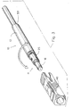
- the optical fibre connector 10 has a ferrule assembly 11 which, at one end is connected to a fibre optic cable with a tubular crimp ring 12 and a tubular cable boot 13, and at the opposite end, is connected to a receptor member.
- the assembly 11 includes a ferrule 15 which has an alignment portion 16 adjoining a base 17.
- the alignment portion 16 is joined end to end with the base 17 along a longitudinal axis.
- a longitudinal bore 18 extends through the alignment portion 16 and the base 17 along the longitudinal axis.
- the optical fibre is received in the longitudinal bore 18.
- the tabs 19 are formed circumferentially around the ferrule 15 and extend outwardly therefrom substantially perpendicularly to the longitudinal axis.
- a coiled compression spring 20 having a center opening 21 is disposed with the base 17 being received in the opening 21 in the compression spring 20 such that the coiled compression spring 20 is around the base 17.
- the ferrule 15 with the compression spring 20 is received in a cable attachment body 25.
- the cable attachment body 25 has a first end 26 oriented toward the ferrule 15 and a second, opposite end 27 oriented toward the crimp ring 12 and cable boot 13.
- a longitudinal bore 28 is formed on a longitudinal axis between the first end 26 and the second end 27.
- the cable attachment body 25 has a plurality of spaced-apart openings 29 formed near the first end 26 of the cable attachment body 25 extending through the cable attachment body 25 and communicating with the longitudinal bore 28.
- a corresponding plurality of spaced-apart longitudinal slots 30 are formed in the cable attachment body, each slot extending through the cable attachment body 25 and communicating with the longitudinal bore 28. Further, each longitudinal slot 30 is disposed between a respective pair of openings 29 so that a plurality of alternating longitudinal slots 30 and openings 29 are formed at the first end 26 of the cable attachment body 25.
- the ferrule 15 is mated with the cable attachment body 25 by inserting the base 17 with the compression spring 20 thereabout into the first end 26 of the cable attachment body 25 so that the base 17 is disposed in the longitudinal bore 28 of the cable attachment body 25.
- the projecting tabs 19 on the ferrule 15 are aligned with corresponding openings 29 and longitudinal slots 30 in the cable attachment body 25.
- every other tab 19 is received in the respective longitudinal slots 30 and the remaining (and alternating) tabs 19 engage the walls 32 (or beams) of the cable attachment body 25 which are formed between the longitudinal slots 30.
- Each tab 19 on the ferrule 15 has a chamfer 33 which deflects the respective beams 32 outwardly from the longitudinal bore 28 in the cable attachment body 25 as the ferrule 15 and the cable attachment body 25 are moved axially. This allows the ferrule assembly 11 to be received in the cable attachment body 25.
- the first end 26 of the cable attachment body 25 has a chamfer complementary to the chamfer 33 on the tabs 19 to facilitate initial deflection of the beams 32.
- the tabs 19 are received in the respective openings 29 with a positive fit and the deflected beams 32 return to the undeflected position. In this manner, the ferrule 15 is retained in the cable attachment body 25 by the urging of the compression spring 20.
- tabs 19 be formed on the ferrule 15, each being approximately 90° apart.
- the portion of the longitudinal bore 18 in the base 17 preferably has a larger diameter than the portion of the longitudinal bore 18 in the alignment portion 16.
- the optical fibre is received in the bore in the alignment portion 16 whereas the optical fibre together with coating for the optical fibre is received in the bore in the base 17.
- Adhesive may also be introduced into the bore in the base 17 to retain the optical fibre in a desired position.
- the optical fibre cable may be mechanically attached to the ferrule 15.
- the assembly 11 formed of the ferrule 15, the compression spring 20 and the cable attachment body 25 is handled as a single piece. It may be factory assembled and delivered as a unit or it may be supplied in component form and assembled prior to termination to an optical fibre cable.
- the assembly 11 is simple to assemble and is cost effective, providing a marketing advantage for the present invention.
- the optical fibre at the end of the alignment portion 16, distal from the cable attachment body 25 is finished by conventional procedures including cleaving, abrasive polishing or thermal polishing.
- the assembly 11 terminated with the optical fibre cable may be tested against another terminated fibre connection with an optical fibre core of known eccentricity and angular orientation. The preferred orientation of the fibre core may be identified by such a test procedure.
- Each unit may be individually tested and oriented or may be oriented with respect to one another. It is preferred that assemblies, and the optical fibres incorporated in each, be oriented in a sector at either 0° or 180° with respect to a keying feature or line of symmetry in order to most efficiently minimize transverse offset loss.
- the retention lugs 35 extend outwardly from the cable attachment body 25 and are approximately perpendicular to the longitudinal axis of the cable attachment body 25.
- the cable attachment body 25 of the assembly 11 is connected to a receptor member by the retention lugs 35.
- One type of receptor member is a plug body 40.
- the plug body 40 has a longitudinal passageway 54 formed therein and has a first end which has a plurality of spaced-apart longitudinal cut outs 42 formed therein.
- the longitudinal cut outs 42 communicate with the longitudinal passageway 54.
- the walls of the plug body 40 between the longitudinal cut outs 42 act as resilient beams 43 such that a plurality of alternating cut outs 42 and beams 43 are formed on the first end 41 of the plug body 40.
- An aperture 44 is formed in each beam 43, each aperture 44 communicating with the longitudinal passageway 54 in the plug body 40.
- the assembly 11 is inserted in the plug body 40 such that the retention lugs 35 deflect the corresponding resilient beams 43 and the respective retention lugs 35 drop into the respective apertures 44 in the respective resilient beams 43.
- the resilient beams 43 return to the undeflected position and lock the respective lugs 35 in place thereby connecting the cable attachment body 25 of the assembly 11 to the plug body 40.
- the respective longitudinal cut outs 42 in the first end 41 of the plug body 40 receive the corresponding retention lugs 35.
- the ferrule 15 portion of the assembly 11 is disposed between the cable attachment body 25 and the plug body 40 and has no direct connecting means with the plug body 40.
- connection between the retention lugs 35 on the cable attachment body 25 and the aperture 44 in plug body 40 is a rotatable connection in that the orientation therebetween can be rotated circumferentially.
- any desired retention lug 35 may be connected to any desired aperture 44 (FIG. 3) with the corresponding orientation and rotation of the adjacent retention lug 35 with respect to a selected cut out 42 to define a sector.
- This rotatable orientation and connection permits the optical fibre core to be oriented into a selected sector.
- the cable attachment body 25 has four retention lugs 35 and the plug body 40 has two diametrically opposed beams 43 and two diametrically opposed cut outs 42 between the beams 43.
- the cable attachment body 25, and consequently the ferrule 15 having the optical fibre core can be oriented with respect to the plug body 40 into a selected one of four sectors, each sector being approximately 90° from the adjoining sector.
- the cable attachment body 25 is formed with a shoulder 45 and a polygonal outer body portion 46.
- the receptor member (or plug body) 40 has a first end 41 which has a corresponding polygonal opening 47 therein communicating with the longitudinal passageway 54 in the receptor member 40.
- At least one, and preferably two or more, resilient locking latches 48 are formed in the walls of the receptor member 40 adjacent to the polygonal opening 47.
- the assembly 11 is inserted into the longitudinal bore in the receptor member 40 and the locking latch 48 engages the shoulder 45 on the cable attachment body 25 which acts as a latch surface, and retains the assembly 11 to the receptor member 40.
- the polygonal opening 47 on the receptor member 40 cooperates with the polygonal outer body portion 46 of the cable attachment body 25 such that rotational movement is resisted between the receptor member 40 and the assembly 11.
- the alignment between the receptor member 40 and the assembly 11 may be selected by rotation of these components prior to engagement. In this manner, one of a plurality of possible rotational orientations can be selected corresponding to the sides of the polygonal outer body portion 46 and the sides of polygonal opening 47 on the receptor member 40. Thus, transverse offset loss can be minimized by selective rotation of the assembly 11 with respect to the receptor member 40.
- the polygon be a square but other multi-sided configurations may be used.
- connection and rotation are selected to reduce transverse offset loss.
- the cable attachment body 25 of the assembly 11 may be oriented and connected with different types of receptor members 40 such as a plug body with a threaded coupling (FIG. 9) or a printed circuit board connector (FIG. 10).
- a plurality of spaced-apart keyways 49 are formed circumferentially on the ferrule 15 near the juncture of the alignment portion 16 and the base 17.
- At least one, and preferably a corresponding plurality, of keys 50 are formed within the plug body 40.
- the keyways 49 and keys 50 are disposed so that the respective keys 50 are received in corresponding keyways 49 when the assembly 11 is received in the plug body 40.
- the keys 50 and keyways 49 are disposed in sectors as described and the keys 50 are received in respective keyways 49 when the assembly 11 is rotatably received in the plug body 40.
- an outer housing 51 is disposed over the receptor member (such as the plug body 40).
- the outer housing 51 has an orientation key 52 formed thereon (FIG. 11).
- the orientation key 52 is used as a reference for rotation and orientation of the assembly 11 with respect to the receptor member.
- the cable attachment body 25 may be made of plastic or metal and may be manufactured by injection molding, die casting or screw machining methods.
- the alignment portion 16 is ceramic but may be made from polymer or metal.
- the exposed cable strength members are fanned over the knurled second end 27 of the cable attachment body 25 and the crimp ring 12 is crimped about the cable attachment body 25 and jacket of the optical fibre cable 53.
- the crimp ring 12 connects the optical fibre cable 53 with the cable attachment body 25.
- the cable boot 13 is slid over the crimp ring 12 and extends outwardly from the cable attachment body 25.
- the method of assembling the optical fibre connector to reduce transverse offset loss is to insert the base 17 in the opening 21 in the compression spring 20.
- the ferrule 15 with the compression spring 20 is inserted into the longitudinal bore 28 in the cable attachment body 25.
- a plurality of tabs 19 on the ferrule assembly 15 are connected to the corresponding plurality of openings 29 in the cable attachment body 25.
- the optical fibre is inserted in the longitudinal bore 18 in the base 17 and the alignment portion 16.
- the optical fibre may be retained within the ferrule 15 either mechanically or adhesively.
- the optical fibre at the end of the alignment portion 16 is finished by cleaning and polishing.
- the components form an assembly 11, the basis of the present invention, which is tested for eccentricity.
- a crimp ring 12 and cable boot 13 may be connected to the second end 27 of the cable attachment body 25 to secure the optical fibre cable 53.
- the basic assembly 11 is connected to a receptor member such as a plug body 40.
- Retention lugs 35 on the cable attachment body 25 are rotatably connected to openings 44 in the plug body 40.
- the assembly 11 is selectively rotated with respect to the plug body 40 and the components are engaged with the locking latch 48 on the plug body 40 engaging the shoulder on the cable attachment body 25.
- the square opening 47 on the plug body 40 cooperates with the square outer body portion 46 of the cable attachment body 25.
- the assembly 11 is oriented with respect to the plug body 40 to reduce transverse offset loss.
- An outer housing 51 may further be disposed over the plug body 40.
- the outer housing 51 has an orientation key 52 formed thereon to assist in orienting the assembly 11 to reduce transverse offset loss.
- the device of the present invention may be used with various types of connectors and is not limited to SC connectors (as shown in Figures 1, 7, 9 and 11).
- an FC style connector embodiment of the present invention comprises the plug body 40 that latches to an FC style coupling nut 60 .
- the plug body 40 is substantially cylindrical with a forward portion 61 and a rearward portion 62 .
- the outer diameter of the forward portion 61 is smaller than the outer diameter of the rearward portion 62, and has an orientation key thereon as is conventional in the FC connector.
- the embodiment of a plug body 40 for an FC style connector according to the teachings of the present invention has apertures 44 and longitudinal cut outs 42 as in the SC embodiment that retainably engage lugs 35 of the ferrule assembly 11. Additionally, the plug body 40 for the FC style connector has two opposing latch members 63 .
- Each latch member 63 comprises a retention shoulder 64 and a latch hook 65 defining a recess 66 therebetween.
- Each latch member 63 has a longitudinal slice defining a pair of independently cantilevered latch beams 67 .
- Each latch beam 67 has a latch hook 65 thereon.
- the latch hook 65 comprises a latch cam surface 68 and a latch shoulder 69 .
- the cooperating FC style coupling nut 60 has a threaded mating portion 70 of the connector as is conventional.
- the FC style coupling nut further has an area of increased annular thickness creating a reduced inner diameter portion of the coupling nut termed an internal retention diameter 71 .
- the width of the retention diameter 71 is less than the width of the recess 66.
- Assembly of the FC connector according to the present invention for a tuned or untuned connector comprises first threading the strain relief boot 13, the crimp eyelet 12, the coupling nut 60 over an unterminated fibre optic cable.
- the ferrule 15, the spring 20, and the cable attachment body 25 are assembled into a ferrule assembly 11 according to the disclosure hereinabove.
- the fibre is stripped and terminated to the ferrule assembly 11.
- This terminated ferrule assembly 11 may be handled and oriented as a unit to make measurements necessary for tuning. Due to the retainable engagement of the ferrule 15 and the cable attachment body 25 which captivates the spring 20, the ferrule assembly 11 advantageously resists disassembly during such handling.
- the rear portion 62 of the plug body 40 is brought over the mating end of the ferrule assembly 11.
- the ferrule assembly 11 is inserted into the plug body 40 in a fixed rotational orientation, the retention lugs 35 resting within apertures 44, and tabs 19 falling within the longitudinal cut outs 42.
- keys 50 fit within keyways 49 to resist rotation of the ferrule 15 relative to the plug body 40.
- the plug body 40 retainably engages the ferrule assembly 11 and may be handled as a unit.
- the mating end 70 of the coupling nut 60 passes over the rearward portion 62 of the plug body 40.
- the latch cam surfaces 68 engage the retention diameter 71 the latch beams 67 deflect inwardly. The inward deflection permits the latch hook 65 to pass the retention diameter 71. As the latch shoulder 69 frees the retention diameter 71, the latch beams 67 return to their undeflected state. The retention diameter 71 is, therefore, received within the recess 66. The retention shoulder 64 and the latch shoulder 69 interferes with opposite ridges of the retention diameter 71 to prevent the plug body's 40 release from the FC coupling nut and captivates the plug body 40 and tuned ferrule assembly 11.
- Assembly of the FC connector according to the present invention for a preassembled untuned connector comprises assembling the ferrule assembly 11, assembling the plug body 40 to the ferrule assembly 11, and bringing the mating end 70 of the FC style coupling nut 60 over the rear portion 62 of the plug body 40 assembled to the ferrule assembly 11 and then the front portion 61 until the retention diameter 71 is received within the recess 66.
- An advantage of the untuned, preassembled embodiment lies in the fact that the ferrule assembly 11 retainably engages the plug body 40, and the plug body 40 retainably engages the coupling nut 60. Retainable engagement of the parts during intermediate assembly steps reduces the possibility of inadvertent disassembly during the manufacturing and assembly process.
Description
| Patent No. | Inventor (s) |
| 3,800,388 | Barnes et al |
| 3,963,143 | Sato |
| 4,019,806 | Fellows et al |
| 4,146,300 | Kaiser |
| 4,239,333 | Dakss et al |
| 4,113,346 | Jackson et al |
| 4,579,418 | Parchet et al |
| 4,738,507 | Palmquist |
| 4,738,508 | Palmquist |
| 4,747,659 | Takahasi |
| 4,753,510 | Sezerman |
| 4,856,865 | Lee |
| 5,142,598 | Tabone |
| 5,146,525 | Tabone |
| 5,216,734 | Grinderslev |
| 5,257,333 | Nodfelt |
| 5,282,259 | Grois et al. |
The plug body comprises opposing cantilever latch members, biased outwardly. The latch members have a retention shoulder and a latch hook defining a recess therebetween. An FC coupling nut has an internal retention diameter received by said recess.
Claims (7)
- An optical fiber connector comprising: a ferrule (15), a cable attachment body (25) retainably engaging said ferrule (15) and a receptor member (40) retainably engaging said cable attachment body (25)
characterised in that engagement of the ferrule (15) with the cable attachment body (25) is by means of tabs (19) on the ferrule (15) that fit in corresponding apertures (29) of the cable attachment body (25) whereby thus engagement both resists rotational displacement between the ferrule (15) and the cable attachment body (25) and retainably engages the ferrule (15) with the cable attachment body (25). - A connector according to claim 1 wherein said receptor member (40) retainably engages said cable attachment body (25) in one of a finite plurality of possible rotational orientations.
- A connector according to any preceding claim wherein said cable attachment body (25) has an outwardly extending retention lug (35) and said receptor member (40) has a retention aperture (44) receiving said retention lug (35).
- A connector according to claim 3 wherein said receptor member (40) has at least two retention apertures (44) opposite each other and said cable attachment body (25) further comprises at least two retention lugs (35) opposite each other received by said retention apertures (44).
- A connector according to any preceding claim wherein said receptor member (40) is a plug body receiving said engaged cable attachment body (25) and ferrule (15) and said connector further comprises an external body (60) receiving said plug body (40) and having an internal retention flange (71) wherein said plug body (40) has opposing cantilever latch members (63) biased outwardly, said latch members (63) have a retention shoulder (64) and a latch hook (65) defining a recess (66) therebetween and wherein said recess (66) receives said internal retention flange (71).
- A connector according to claim 5 wherein each said latch member (63) comprises an independently cantilevered latch beam (67), each latch beam (67) having said latch hook (65) thereon defining a respective recess (66) between said respective latch hook (65) and said retention shoulder (64) and said internal retention flange (71) is received by each said respective recess (66).
- A connector according to any preceding claim wherein the apertures (29) of the cable attachment body (25) are in wall portions thereof and formed between longitudinal slots (30) thereof.
Priority Applications (1)
| Application Number | Priority Date | Filing Date | Title |
|---|---|---|---|
| EP01200106A EP1092997A1 (en) | 1994-06-22 | 1995-04-27 | Optical fiber connector having enhanced assembly means |
Applications Claiming Priority (5)
| Application Number | Priority Date | Filing Date | Title |
|---|---|---|---|
| US26412494A | 1994-06-22 | 1994-06-22 | |
| US264124 | 1994-06-22 | ||
| US38103595A | 1995-01-31 | 1995-01-31 | |
| US381035 | 1995-01-31 | ||
| PCT/US1995/005270 WO1995035520A1 (en) | 1994-06-22 | 1995-04-27 | Optical fiber connector having enhanced assembly means |
Related Child Applications (1)
| Application Number | Title | Priority Date | Filing Date |
|---|---|---|---|
| EP01200106A Division EP1092997A1 (en) | 1994-06-22 | 1995-04-27 | Optical fiber connector having enhanced assembly means |
Publications (2)
| Publication Number | Publication Date |
|---|---|
| EP0766838A1 EP0766838A1 (en) | 1997-04-09 |
| EP0766838B1 true EP0766838B1 (en) | 2002-03-06 |
Family
ID=26950270
Family Applications (2)
| Application Number | Title | Priority Date | Filing Date |
|---|---|---|---|
| EP95918318A Expired - Lifetime EP0766838B1 (en) | 1994-06-22 | 1995-04-27 | Optical fiber connector having enhanced assembly means |
| EP01200106A Withdrawn EP1092997A1 (en) | 1994-06-22 | 1995-04-27 | Optical fiber connector having enhanced assembly means |
Family Applications After (1)
| Application Number | Title | Priority Date | Filing Date |
|---|---|---|---|
| EP01200106A Withdrawn EP1092997A1 (en) | 1994-06-22 | 1995-04-27 | Optical fiber connector having enhanced assembly means |
Country Status (8)
| Country | Link |
|---|---|
| US (1) | US5809192A (en) |
| EP (2) | EP0766838B1 (en) |
| JP (1) | JP3483889B2 (en) |
| CN (1) | CN1125357C (en) |
| AU (1) | AU2429195A (en) |
| DE (1) | DE69525746T2 (en) |
| PL (1) | PL317995A1 (en) |
| WO (1) | WO1995035520A1 (en) |
Families Citing this family (82)
| Publication number | Priority date | Publication date | Assignee | Title |
|---|---|---|---|---|
| JP3798455B2 (en) * | 1994-11-04 | 2006-07-19 | ザ ウィタカー コーポレーション | Fiber optic connector |
| JP3099113B2 (en) * | 1996-11-13 | 2000-10-16 | モレックス インコーポレーテッド | Optical fiber plug and optical connector |
| JPH10311934A (en) * | 1997-05-12 | 1998-11-24 | Kiyousera Elco Kk | Plastic optical fiber connector |
| JPH1138276A (en) * | 1997-07-22 | 1999-02-12 | Seiko Giken:Kk | Structure of optical connector and its alignment method |
| DE19754772C2 (en) * | 1997-11-28 | 1999-10-07 | Siemens Ag | Interconnects |
| JPH11305070A (en) * | 1998-04-24 | 1999-11-05 | Yazaki Corp | Optical fiber connector |
| US6435730B1 (en) * | 1998-05-06 | 2002-08-20 | The Whitaker Corporation | Optical fiber connector with improved ferrule float feature |
| FR2787890B1 (en) | 1998-12-24 | 2002-01-04 | Radiall Sa | OPTICAL CONNECTOR ELEMENT WITH MONOBLOCK BODY |
| US6464408B1 (en) | 1998-12-28 | 2002-10-15 | Computer Crafts, Inc. | Fiber optic connectors |
| US6454464B1 (en) | 1998-12-28 | 2002-09-24 | Computer Crafts, Inc. | Fiber optic connectors and transceiver test devices |
| EP1115014A1 (en) | 2000-01-06 | 2001-07-11 | Diamond SA | Plug portion for an optical connection and its assembly method |
| EP1079251B1 (en) * | 1999-08-25 | 2005-11-02 | Interlemo Holding S.A. | A method for manufacturing a fibre optic male contact |
| US6419402B1 (en) | 1999-12-13 | 2002-07-16 | Adc Telecommunications, Inc. | Fiber optic connector and method for assembling |
| US6254283B1 (en) * | 2000-02-22 | 2001-07-03 | Itt Manufacturing Enterprises, Inc. | Terminus body retention |
| CN1200298C (en) * | 2000-05-12 | 2005-05-04 | 稻垣武雄 | Optical fiber connector |
| JP3641201B2 (en) * | 2000-10-31 | 2005-04-20 | 三和電気工業株式会社 | Optical connector plug |
| US6572273B1 (en) * | 2000-11-07 | 2003-06-03 | Itt Manufacturing Enterprises, Inc. | Fiber optic connector with removable alignment sleeve |
| US6540410B2 (en) * | 2000-12-18 | 2003-04-01 | Corning Cable Systems Llc | Panel-mounted fiber optic connector |
| US6428215B1 (en) | 2000-12-27 | 2002-08-06 | Adc Telecommunications, Inc. | Tunable fiber optic connector and method for assembling |
| GB2371374A (en) * | 2001-01-18 | 2002-07-24 | Mao-Hsiang Chen | Optical fibre plug connector with opposing holes for elastic inserts |
| US20020164130A1 (en) * | 2001-05-07 | 2002-11-07 | Elkins Robert B. | Fiber optic module attachment including a fiber locating connector |
| US6669377B2 (en) * | 2001-06-11 | 2003-12-30 | Corning Cable Systems Llc | Fiber optic connector and an associated pin retainer |
| US6550979B1 (en) * | 2001-10-19 | 2003-04-22 | Corning Cable Systems Llc | Floating connector subassembly and connector including same |
| US6629782B2 (en) | 2002-02-04 | 2003-10-07 | Adc Telecommunications, Inc. | Tuned fiber optic connector and method |
| US6637946B2 (en) * | 2002-03-14 | 2003-10-28 | Yu-Feng Cheng | Adapter for an optical fiber plug |
| US6702475B1 (en) | 2002-05-07 | 2004-03-09 | Cisco Technology, Inc. | Release system for optical connectors |
| US6655851B1 (en) * | 2002-05-22 | 2003-12-02 | Fiberon Technolgies, Inc. | Optical fiber connector |
| EP1394585B1 (en) * | 2002-08-08 | 2010-11-17 | TYCO Electronics Corporation | Optical fiber connector with ferrule radial orientation control |
| US6626710B1 (en) * | 2002-09-30 | 2003-09-30 | Shun-Chih Tsai Huang | Signal plug structure |
| US6913396B2 (en) * | 2002-11-01 | 2005-07-05 | Adc Telecommunications, Inc. | Tunable fiber optic connector and device and method for tuning a connector |
| DE10257520B4 (en) * | 2002-12-10 | 2006-09-14 | Ims Connector Systems Gmbh | Fiber optic connector |
| US6918704B2 (en) * | 2003-01-30 | 2005-07-19 | Panduit Corp. | Tunable fiber optic connector |
| US6962445B2 (en) | 2003-09-08 | 2005-11-08 | Adc Telecommunications, Inc. | Ruggedized fiber optic connection |
| JP3925933B2 (en) * | 2004-04-02 | 2007-06-06 | 日本航空電子工業株式会社 | Optical connector disassembly jig |
| KR100507543B1 (en) * | 2004-06-30 | 2005-08-09 | 주식회사 골드텔 | Optical connector |
| FR2873453B1 (en) * | 2004-07-26 | 2006-11-24 | Nexans Sa | CONNECTOR FOR OPTICAL FIBER |
| US20060115219A1 (en) * | 2004-11-29 | 2006-06-01 | Mudd Ronald L | Optical fiber connector |
| JP4090063B2 (en) | 2005-02-15 | 2008-05-28 | 日本航空電子工業株式会社 | Optical connector |
| CN101506707B (en) * | 2006-06-15 | 2011-03-23 | 泰科电子公司 | Connector for jacketed optical fiber cable |
| US7782401B1 (en) * | 2006-06-20 | 2010-08-24 | Kolorific, Inc. | Method and system for digital image scaling with sharpness enhancement and transient improvement |
| US20080013956A1 (en) * | 2006-07-14 | 2008-01-17 | Tenvera, Inc. | Provisioning of Services Via an Optical Fiber Network |
| US20080013893A1 (en) * | 2006-07-14 | 2008-01-17 | Tenvera, Inc. | Optical Fiber Ferrule and Ferrule Receiver, and Method for Manufacturing the Same |
| US20080011514A1 (en) * | 2006-07-14 | 2008-01-17 | Tenvera, Inc. | Optical Fiber Distribution Apparatus and Method |
| US20080013957A1 (en) * | 2006-07-14 | 2008-01-17 | Tenvera, Inc. | Service Aggregation Gateway |
| US20080011990A1 (en) * | 2006-07-14 | 2008-01-17 | Tenvera, Inc. | Installation of Fiber Optic Cables |
| US20080013909A1 (en) * | 2006-07-14 | 2008-01-17 | Tenvera, Inc. | Modular Optical Fiber Network Interface |
| US7591595B2 (en) | 2007-01-24 | 2009-09-22 | Adc Telelcommunications, Inc. | Hardened fiber optic adapter |
| US7572065B2 (en) | 2007-01-24 | 2009-08-11 | Adc Telecommunications, Inc. | Hardened fiber optic connector |
| GB2448935B8 (en) * | 2007-05-04 | 2010-08-25 | Miniflex Ltd | Opticle fibre connector |
| DE102007033246A1 (en) * | 2007-07-17 | 2009-01-22 | Euromicron Werkzeuge Gmbh | Plug for terminating optical transmission media |
| US7744286B2 (en) | 2007-12-11 | 2010-06-29 | Adc Telecommunications, Inc. | Hardened fiber optic connection system with multiple configurations |
| US8038356B2 (en) | 2008-04-21 | 2011-10-18 | Adc Telecommunications, Inc. | Hardened fiber optic connector with connector body joined to cylindrical cable by unitary housing |
| CH703904A2 (en) * | 2010-10-01 | 2012-04-13 | Huber+Suhner Ag | Connector. |
| US8753022B2 (en) | 2010-11-30 | 2014-06-17 | Adc Telecommunications, Inc. | LC connector and method of assembly |
| US8579520B2 (en) | 2011-02-04 | 2013-11-12 | Ppc Broadband, Inc. | Latching optical digital audio connector and method of use thereof |
| WO2013177016A1 (en) * | 2012-05-22 | 2013-11-28 | Adc Telecommunications, Inc. | Ruggedized fiber optic connector |
| US9081154B2 (en) | 2012-09-12 | 2015-07-14 | Tyco Electronics Raychem Bvba | Method of tuning a fiber optic connector |
| JP5913020B2 (en) * | 2012-09-13 | 2016-04-27 | 株式会社オートネットワーク技術研究所 | Optical connector and optical connector manufacturing method |
| US9146362B2 (en) | 2012-09-21 | 2015-09-29 | Adc Telecommunications, Inc. | Insertion and removal tool for a fiber optic ferrule alignment sleeve |
| AU2013352273A1 (en) | 2012-11-30 | 2015-06-04 | Tyco Electronics Corporation | Distributed split configuration for multi-dwelling unit |
| CN104823090B (en) | 2012-11-30 | 2017-04-05 | 泰科电子公司 | The joints of optical fibre with field-attachable outconnector housing |
| JP6138533B2 (en) * | 2013-03-18 | 2017-05-31 | 株式会社 オプトクエスト | Optical connector for multi-core fiber |
| EP3014322B1 (en) | 2013-06-27 | 2018-09-19 | CommScope Connectivity Belgium BVBA | Fiber optic cable anchoring device for use with fiber optic connectors and methods of using the same |
| CN103323922B (en) * | 2013-07-08 | 2016-03-02 | 无锡光云通信科技有限公司 | A kind of active optical cable |
| CN104849816B (en) | 2014-02-14 | 2017-01-11 | 泰科电子(上海)有限公司 | Optical fiber connector and assembly method therefor |
| CN104849815B (en) | 2014-02-14 | 2017-01-18 | 泰科电子(上海)有限公司 | Optical fiber connector and assembly method therefor |
| CN105445862B (en) | 2014-07-09 | 2018-01-19 | 泰科电子(上海)有限公司 | The joints of optical fibre and its on-site assembly method |
| ES2848702T3 (en) * | 2014-08-06 | 2021-08-11 | Prysmian Spa | Fiber optic connector set |
| US10180541B2 (en) | 2014-12-19 | 2019-01-15 | CommScope Connectivity Belgium BVBA | Hardened fiber optic connector with pre-compressed spring |
| EP3296785A4 (en) | 2015-05-15 | 2019-05-29 | ADC Telecommunications (Shanghai) Distribution Co., Ltd. | Alignment sleeve assembly and optical fibre adapter |
| CN106291826B (en) * | 2015-05-20 | 2019-05-28 | 华为技术有限公司 | Plug head protector, fiber connector component, Optical fiber plug and the network equipment |
| US10620385B2 (en) * | 2015-11-30 | 2020-04-14 | Commscope Technologies Llc | Fiber optic connector and assembly thereof |
| WO2017106514A1 (en) | 2015-12-16 | 2017-06-22 | Commscope Technologies Llc | Field installed fiber optic connector |
| EP3299858B1 (en) | 2016-09-23 | 2022-06-01 | Hexatronic Group AB | Method of assembling a fibre connector |
| US10718910B2 (en) * | 2017-05-03 | 2020-07-21 | Senko Advanced Components, Inc | Field terminated ruggedized fiber optic connector system |
| US10520686B2 (en) * | 2017-05-18 | 2019-12-31 | Senko Advanced Components, Inc. | Optical connector with one-piece body |
| WO2019152623A1 (en) | 2018-01-31 | 2019-08-08 | Commscope Technologies Llc | Tunable fiber optic connectors |
| WO2019194922A1 (en) | 2018-04-02 | 2019-10-10 | Senko Advanced Components, Inc | Hybrid ingress protected connector and adapter assembly |
| EP3908867A4 (en) * | 2019-01-10 | 2022-09-21 | PPC Broadband, Inc. | Fiber optical connector |
| CN211043735U (en) * | 2019-08-02 | 2020-07-17 | 广东亿源通科技股份有限公司 | Polarization maintaining connector |
| WO2021144653A1 (en) * | 2020-01-17 | 2021-07-22 | Ppc Broadband Fiber Ltd. | Optical fiber connectors |
| US11966088B2 (en) | 2020-01-17 | 2024-04-23 | Ppc Broadband Fiber Ltd. | Optical fiber connectors |
Family Cites Families (29)
| Publication number | Priority date | Publication date | Assignee | Title |
|---|---|---|---|---|
| US3984174A (en) * | 1975-04-28 | 1976-10-05 | International Telephone And Telegraph Corporation | Fiber optic connector with transparent cable sleeve |
| DE2845420C2 (en) * | 1978-10-18 | 1984-11-08 | Bunker Ramo Corp., Oak Brook, Ill. | Fiber optic plug connection |
| US4762389A (en) * | 1984-03-30 | 1988-08-09 | Nec Corporation | Optical fiber connector |
| JPS60178809U (en) * | 1984-05-07 | 1985-11-27 | 第一電子工業株式会社 | Optical fiber connector ferrule holding structure |
| JPS61213811A (en) * | 1985-03-19 | 1986-09-22 | Sumitomo Electric Ind Ltd | Optical connector |
| JPS61185019U (en) * | 1985-05-09 | 1986-11-18 | ||
| US4735480A (en) * | 1985-11-20 | 1988-04-05 | Raychem Corp. | Optical fiber connector |
| DE68915032T2 (en) * | 1988-02-23 | 1995-01-26 | Whitaker Corp | Sheathed plug for optical cable. |
| DE58908131D1 (en) * | 1988-06-09 | 1994-09-08 | Erni Elektroapp | Two-part connector for fiber optic cables. |
| US4936662A (en) * | 1989-02-10 | 1990-06-26 | Minnesota Mining And Manufacturing Company | Optical fiber connector |
| US5082344A (en) * | 1990-03-09 | 1992-01-21 | Mulholland Denis G | Adapter assembly with improved receptacle for a push-pull coupling type of optical fiber connector |
| US5142597A (en) * | 1990-07-27 | 1992-08-25 | Amp Incorporated | Interconnect assembly for wall outlet |
| US5337385A (en) * | 1991-03-01 | 1994-08-09 | The Whitaker Corporation | Optical waveguide terminating device |
| US5230032A (en) * | 1991-05-09 | 1993-07-20 | Itt Corporation | Abutting tips fiber optic connector and method of making same |
| JP2538394Y2 (en) * | 1991-05-29 | 1997-06-11 | 住友電気工業株式会社 | Optical connector |
| US5261019A (en) * | 1992-01-02 | 1993-11-09 | Adc Telecommunications, Inc. | Fiber optic connector |
| US5214732A (en) * | 1992-01-02 | 1993-05-25 | Adc Telecommunications, Inc. | Optical fiber retention mechanism for securing optical fiber cable |
| US5193133A (en) * | 1992-01-21 | 1993-03-09 | Methode Electronics, Inc. | Method of terminating optical fiber utilizing a plastic alignment ferrule with polishing pedestal |
| US5222169A (en) * | 1992-02-18 | 1993-06-22 | Foxconn International, Inc. | Optical fiber connector assembly |
| US5212752A (en) * | 1992-05-27 | 1993-05-18 | At&T Bell Laboratories | Optical fiber ferrule connector having enhanced provisions for tuning |
| US5265183A (en) * | 1992-07-02 | 1993-11-23 | Molex Incorporated | Fiber optic connector and tool for assembling same |
| JPH0675142A (en) * | 1992-08-25 | 1994-03-18 | Yamaichi Electron Co Ltd | Optical connector |
| US5265182A (en) * | 1992-10-13 | 1993-11-23 | Hughes Aircraft Company | Retention and release mechanism for fiber optic alignment sleeve retainer |
| US5337386A (en) * | 1992-12-22 | 1994-08-09 | Hughes Aircraft Company | Single channel snap-lock fiber optic connector |
| US5283849A (en) * | 1993-02-01 | 1994-02-01 | Siecor Corporation | Optical connector preassembly |
| US5321784A (en) * | 1993-02-18 | 1994-06-14 | Minnesota Mining And Manufacturing Company | Pull-proof, modular fiber optic connector system |
| US5287425A (en) * | 1993-02-26 | 1994-02-15 | Foxconn International, Inc. | Optical fiber SC type connector assembly with partly pre-assembled components |
| US5436995A (en) * | 1993-05-14 | 1995-07-25 | Nippon Telegraph And Telephone Corporation | Optical fiber connector unit and optical fiber connector |
| US5428703A (en) * | 1994-02-18 | 1995-06-27 | Augat Inc. | One-piece SC fiber optic connector |
-
1995
- 1995-04-27 JP JP50214396A patent/JP3483889B2/en not_active Expired - Lifetime
- 1995-04-27 DE DE69525746T patent/DE69525746T2/en not_active Expired - Fee Related
- 1995-04-27 AU AU24291/95A patent/AU2429195A/en not_active Abandoned
- 1995-04-27 EP EP95918318A patent/EP0766838B1/en not_active Expired - Lifetime
- 1995-04-27 WO PCT/US1995/005270 patent/WO1995035520A1/en active IP Right Grant
- 1995-04-27 PL PL95317995A patent/PL317995A1/en unknown
- 1995-04-27 EP EP01200106A patent/EP1092997A1/en not_active Withdrawn
- 1995-04-27 CN CN95194728A patent/CN1125357C/en not_active Expired - Fee Related
-
1996
- 1996-03-05 US US08/611,312 patent/US5809192A/en not_active Expired - Lifetime
Also Published As
| Publication number | Publication date |
|---|---|
| PL317995A1 (en) | 1997-05-12 |
| DE69525746D1 (en) | 2002-04-11 |
| WO1995035520A1 (en) | 1995-12-28 |
| EP0766838A1 (en) | 1997-04-09 |
| EP1092997A1 (en) | 2001-04-18 |
| DE69525746T2 (en) | 2002-10-17 |
| JPH10509523A (en) | 1998-09-14 |
| CN1156509A (en) | 1997-08-06 |
| US5809192A (en) | 1998-09-15 |
| AU2429195A (en) | 1996-01-15 |
| JP3483889B2 (en) | 2004-01-06 |
| CN1125357C (en) | 2003-10-22 |
Similar Documents
| Publication | Publication Date | Title |
|---|---|---|
| EP0766838B1 (en) | Optical fiber connector having enhanced assembly means | |
| US5682451A (en) | Device with internal features for rotational alignment of non-cylindrically symmetrical optical elements | |
| US5633970A (en) | Device with internal asymmetrical features for rotational alignment of non-symmetrical articles | |
| US7530745B2 (en) | Fiber optic connector and method | |
| US6550979B1 (en) | Floating connector subassembly and connector including same | |
| JP4722943B2 (en) | Optical fiber connector assembly | |
| US6695489B2 (en) | Tunable fiber optic connector and method for assembling | |
| US8753022B2 (en) | LC connector and method of assembly | |
| US7147385B2 (en) | Fiber optic connector and method | |
| EP1148366B1 (en) | Eccentricity adjustable optical fiber connector | |
| EP0660144A1 (en) | Optical connector | |
| CA2237481A1 (en) | Adapter and guide pin assembly for coupling of fiber optic connectors | |
| WO1999064917A2 (en) | Fiber optic connector | |
| EP0938003A1 (en) | Tunable multiple fiber optical connector | |
| EP1640755B1 (en) | Optical connector assemblies | |
| US7204643B2 (en) | Method of producing a receptacle-type optical connector | |
| JPH07270646A (en) | Optical fiber connector | |
| JPH0756053A (en) | Whirl stop structure for optical connector ferrule | |
| JPH01271712A (en) | Optical connector plug |
Legal Events
| Date | Code | Title | Description |
|---|---|---|---|
| PUAI | Public reference made under article 153(3) epc to a published international application that has entered the european phase |
Free format text: ORIGINAL CODE: 0009012 |
|
| 17P | Request for examination filed |
Effective date: 19970113 |
|
| AK | Designated contracting states |
Kind code of ref document: A1 Designated state(s): CH DE ES FR GB IT LI NL |
|
| 17Q | First examination report despatched |
Effective date: 19980113 |
|
| GRAG | Despatch of communication of intention to grant |
Free format text: ORIGINAL CODE: EPIDOS AGRA |
|
| GRAG | Despatch of communication of intention to grant |
Free format text: ORIGINAL CODE: EPIDOS AGRA |
|
| GRAH | Despatch of communication of intention to grant a patent |
Free format text: ORIGINAL CODE: EPIDOS IGRA |
|
| GRAH | Despatch of communication of intention to grant a patent |
Free format text: ORIGINAL CODE: EPIDOS IGRA |
|
| REG | Reference to a national code |
Ref country code: GB Ref legal event code: IF02 |
|
| GRAA | (expected) grant |
Free format text: ORIGINAL CODE: 0009210 |
|
| AK | Designated contracting states |
Kind code of ref document: B1 Designated state(s): CH DE ES FR GB IT LI NL |
|
| PG25 | Lapsed in a contracting state [announced via postgrant information from national office to epo] |
Ref country code: LI Free format text: LAPSE BECAUSE OF FAILURE TO SUBMIT A TRANSLATION OF THE DESCRIPTION OR TO PAY THE FEE WITHIN THE PRESCRIBED TIME-LIMIT Effective date: 20020306 Ref country code: CH Free format text: LAPSE BECAUSE OF FAILURE TO SUBMIT A TRANSLATION OF THE DESCRIPTION OR TO PAY THE FEE WITHIN THE PRESCRIBED TIME-LIMIT Effective date: 20020306 |
|
| REG | Reference to a national code |
Ref country code: CH Ref legal event code: EP |
|
| REF | Corresponds to: |
Ref document number: 69525746 Country of ref document: DE Date of ref document: 20020411 |
|
| ET | Fr: translation filed | ||
| REG | Reference to a national code |
Ref country code: CH Ref legal event code: PL |
|
| PG25 | Lapsed in a contracting state [announced via postgrant information from national office to epo] |
Ref country code: ES Free format text: LAPSE BECAUSE OF FAILURE TO SUBMIT A TRANSLATION OF THE DESCRIPTION OR TO PAY THE FEE WITHIN THE PRESCRIBED TIME-LIMIT Effective date: 20020925 |
|
| PLBE | No opposition filed within time limit |
Free format text: ORIGINAL CODE: 0009261 |
|
| STAA | Information on the status of an ep patent application or granted ep patent |
Free format text: STATUS: NO OPPOSITION FILED WITHIN TIME LIMIT |
|
| 26N | No opposition filed |
Effective date: 20021209 |
|
| PGFP | Annual fee paid to national office [announced via postgrant information from national office to epo] |
Ref country code: NL Payment date: 20090423 Year of fee payment: 15 Ref country code: IT Payment date: 20090429 Year of fee payment: 15 Ref country code: FR Payment date: 20090417 Year of fee payment: 15 Ref country code: DE Payment date: 20090429 Year of fee payment: 15 |
|
| PGFP | Annual fee paid to national office [announced via postgrant information from national office to epo] |
Ref country code: GB Payment date: 20090429 Year of fee payment: 15 |
|
| REG | Reference to a national code |
Ref country code: NL Ref legal event code: V1 Effective date: 20101101 |
|
| GBPC | Gb: european patent ceased through non-payment of renewal fee |
Effective date: 20100427 |
|
| REG | Reference to a national code |
Ref country code: FR Ref legal event code: ST Effective date: 20101230 |
|
| PG25 | Lapsed in a contracting state [announced via postgrant information from national office to epo] |
Ref country code: NL Free format text: LAPSE BECAUSE OF NON-PAYMENT OF DUE FEES Effective date: 20101101 |
|
| PG25 | Lapsed in a contracting state [announced via postgrant information from national office to epo] |
Ref country code: DE Free format text: LAPSE BECAUSE OF NON-PAYMENT OF DUE FEES Effective date: 20101103 |
|
| PG25 | Lapsed in a contracting state [announced via postgrant information from national office to epo] |
Ref country code: GB Free format text: LAPSE BECAUSE OF NON-PAYMENT OF DUE FEES Effective date: 20100427 Ref country code: IT Free format text: LAPSE BECAUSE OF NON-PAYMENT OF DUE FEES Effective date: 20100427 |
|
| PG25 | Lapsed in a contracting state [announced via postgrant information from national office to epo] |
Ref country code: FR Free format text: LAPSE BECAUSE OF NON-PAYMENT OF DUE FEES Effective date: 20100430 |