EP0766420B1 - Method and circuit for the detection of a synchronisation pattern - Google Patents
Method and circuit for the detection of a synchronisation pattern Download PDFInfo
- Publication number
- EP0766420B1 EP0766420B1 EP96114023A EP96114023A EP0766420B1 EP 0766420 B1 EP0766420 B1 EP 0766420B1 EP 96114023 A EP96114023 A EP 96114023A EP 96114023 A EP96114023 A EP 96114023A EP 0766420 B1 EP0766420 B1 EP 0766420B1
- Authority
- EP
- European Patent Office
- Prior art keywords
- counting means
- data values
- synchronization
- synchronization identifier
- detected
- Prior art date
- Legal status (The legal status is an assumption and is not a legal conclusion. Google has not performed a legal analysis and makes no representation as to the accuracy of the status listed.)
- Expired - Lifetime
Links
Images

Classifications
-
- H—ELECTRICITY
- H04—ELECTRIC COMMUNICATION TECHNIQUE
- H04J—MULTIPLEX COMMUNICATION
- H04J3/00—Time-division multiplex systems
- H04J3/02—Details
- H04J3/06—Synchronising arrangements
- H04J3/0602—Systems characterised by the synchronising information used
- H04J3/0605—Special codes used as synchronising signal
- H04J3/0608—Detectors therefor, e.g. correlators, state machines
Definitions
- the invention relates to a method for synchronization a sequence of digital data values according to the generic term of Claim 1.
- the invention also relates to a Circuit arrangement for performing the method.
- the applicant is aware of a method in which according to the occurrence of a first synchronization identifier in the data bit stream the number of the distance between two synchronization identifiers received data bits forming is counted. If after this number of data bits again a synchronous identifier indicates that the synchronous frame has been found.
- the special Bit pattern of the synchronous identifier can occur.
- the synchronization process is extended. While the respective data packets go out of synchronization lost.
- a method and a circuit arrangement for detecting the beginning of a frame described frame-synchronized signal The beginning of the frame is characterized by a predetermined bit sequence; within the frame is in a certain frame position a second predetermined bit sequence is provided.
- the circuit contains means for the first and second predetermined bit sequence determine.
- a frame counter is activated when the first Bit sequence is recognized and counts up to the frame position, on which the second bit sequence is provided.
- the synchronous frame is then recognized as detected if after the detection of the first bit sequence, the second bit sequence at the predetermined one Frame position is recognized.
- the frame recognition can only be regarded as fulfilled if multiple times the first and second bit sequence at the specified distance occur to each other.
- the object of the invention is to provide a method for Synchronization to a sequence of digital data values that at a distance from a predetermined number of data values each contains a synchronous identifier, by which the sequence the synchronous identifiers are recognized more quickly and the synchronization state is manufactured faster.
- Another The task is to specify a circuit arrangement for Execution of the procedure.
- the task relates to the method by a method according to the features of claim 1 solved.
- a circuit arrangement for performing the method is specified in claim 5.
- At least two counting processes are carried out executed in parallel. This makes several possible Sequences of synchronization bit patterns in parallel thereafter checks whether there is actually a synchronization bit sequence is present.
- the respective counting and Verification processes work accordingly.
- the security in the case of synchronous detection this can increase that synchronization is only determined when several synchronous identifiers recognized in the specified packet spacing have been.
- a counter is expediently used for this purpose counted upwards if the specified number of Data values a synchronous bit pattern is recognized, and counted down if such at the specified distance is not recognized. If the counter reading a threshold exceeds, this indicates that the synchronization bit pattern sequence has been recognized.
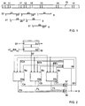
- FIG. 1 contains a data stream 10 which contains a large number of digital data values (bits).
- the data stream contains coded and formatted information according to the MPEG standard for the transmission of digital image data.
- the data stream 10 has synchronous bit patterns 11 ... 15 at equidistant intervals.
- the bit pattern is fixed and known to the receiver, for example 47 hex or B8 hex .
- the method according to the invention serves to check the received data bit stream for the presence of the synchronous bit pattern. For this purpose, a window with the length of the synchronous identifier of 8 bits is passed over the data bit stream and it is checked whether the synchronous bit sequence 47 hex or B8 hex is present. If necessary, the comparison can also be regarded as fulfilled if there is a match in less than these 8 bits within the window of 8 bits.
- the synchronization process can be extended as a result, but the circuitry and the computing speed are increased. The number of bits that must match the synchronous bit pattern within the check window for the comparison to be considered to be fulfilled depends on the type of data received and the requirements for synchronization in terms of implementation effort and speed and must be set accordingly.
- the data stream 10 first recognized the synchronous bit pattern in section 16.
- a first checking process 22 is carried out, to determine if bit pattern 16 is a continuous Listened to sequence of actual sync bit patterns.
- a first counting process 20 is started, that number counts from received data bits, which according to the definition between two synchronous bit patterns, i.e. the frames or Packet length, possibly reduced by the number of bits the synchronous identifier itself.
- the counting process is in place 21 ended.
- bit pattern sections 16, 17 of the synchronous bit pattern Data stream 10 is not an actual synchronous bit sequence, in which the synchronous bit pattern would have to occur continuously. Rather, the bit pattern sections 16, 17 are sections of the Data contents of the data packets that happen to be the bit pattern have the synchronous identifier.
- the data stream 10 continues continuously for the presence of a synchronous bit pattern checked. It is noted that in section 11 also a Bit pattern is present that corresponds to the synchronous bit pattern.
- the checking process 27 now determines whether this Bit pattern 11 of a continuous sequence of synchronous identifiers belongs. By means of the counting process 25 is the agreed Distance between two synchronous identifiers counted.
- the data stream 10 is checked at the point 26, wherein it is determined that the synchronous bit pattern 12 is present.
- After the subsequent counting process 28 it is again determined that the synchronous bit pattern 13 at the predetermined distance occurs.
- the match counter for this verification process 27 now has the value "3". This means that the synchronous bit pattern sequence 11, 12, 13, 14 is found. To the Increasing the level of recognition reliability can make the decision threshold the counting process 27 from "3" to higher threshold values increase.
- each of the synchronous bit patterns that occur in the data stream 10 namely 16, 17 or 11, 12, 13 or 18 as possible synchronous bit sequence followed. It is determined whether or not the consecutive synchronous bit pattern actually is present. This presence is determined when the Synchronous bit pattern in the present example at least three times occurred at the prescribed distance.
- a comparison device 50 is provided, by means of which the received data stream DI, which corresponds to the data stream 10 of FIG. 1, is checked for the presence of the synchronous identifier, for example 47 hex / B8 hex .
- the synchronous byte detector 50 contains an 8-bit shift register 51, to which the data stream DI is supplied.
- the content of the shift register is compared in a comparator 52 with the synchronous identifier 47 hex or B8 hex .
- each of the synchronization circuits 53a, 53b, 53c contains 3 a counter 54a, 54b and 54c for counting the distance between two synchronous bit patterns in the data stream as agreed.
- the reference symbol portions a, b, c indicate that the each in Figure 3 for all synchronous circuits only once represented counter of the synchronous circuit 53a, 53b or 53c.
- the counter 54 expediently counts that Length of the data part of a synchronous bit pattern and subsequent Data packet containing data content. Beyond that a match counter in each synchronization circuit 55a, 55b and 55c provided by which the repeated occurrence of the synchronous bit pattern is counted if it is in the specified Distance of the packet length occurs.
- a control device 58 ensures the sequence control the circuit.
- the control device 58 contains a list of free, not yet activated synchronous circuits 53a, 53b or 53c. According to one output by the synchronous byte detector 50 Impulse SF, which is the presence of a synchronous bit pattern indicates, one of the free synchronous circuits is activated. Only if one of the frame length counters 54a, 54b or 54c has just completed its counting process and does so by a corresponding signal Ca, Cb or Cc is only shown in of the synchronization circuit in which the frame counter has expired and activated the corresponding signal, the match counter 55a, 55b or 55c is incremented by +1.
- the synchronization circuits 53a, 53b, 53c each the signal Ca, Cb and Cc, respectively, these signals can be linked via an OR link 57.
- the Output signal GD of the OR gate 57 serves that only in the synchronization circuit generating the signal GD, but not in the other synchronization circuits of the Synchronous byte detector pulse SF is recorded. To do this the signal GD to all synchronization circuits 53a, 53b, 53c fed back. Because of the synchronously clocked operating mode the circuit is also the feedback of the signal GD on the synchronization circuit that the signal GD in Generated clock beforehand, possible without conflict. So it will ensured that only one of the circuits 53a, 53b, 53c is influenced by a pulse of the signal SF at the same time.
- Each of the synchronization circuits 53a, 53b, 53c a signal Ba, Bb or Bc emitted, which indicates that the respective Synchronization circuit is activated, that is the counting function of the frame or match counter contained therein running.
- the control device 58 receives the signals Ba, Bb, Bc to the list of free channels kept there Update synchronization circuits. When a sync byte detector pulse SF is present and the signal GD is not is set, this means that a synchronous identifier has occurred is without one of the frame counters starting its counting process has just ended. Then the controller inputs 58 via respective start signal SEa, SEb or SEc a previously dormant Synchronization circuit for activation free, the corresponding frame counter is activated.
- the list of free synchronization circuits in the control device 58 will be updated accordingly. Are all synchronization circuits active, no further synchronization circuit is activated started. Once one of the match counters of the synchronization circuits 53a, 53b or 53c Has reached threshold value ("3" in the present example) this is indicated by a corresponding signal Fa, Fb or Fc. These signals are fed to an OR operation 56, the Output signal S indicates that the sequence of synchronization identifiers is found. The circuit of Figure 2 receiving device containing can now receive the received data sequence evaluate packet-synchronized.
- Each of the synchronization circuits 53a, 53b, 53c is through the circuit shown in Figure 3 realized.
- the frame counter 54 the frame length FL is fed to the connection 60.
- the counter 54 counts downwards starting with the counter reading FL for counter reading "0".
- the signal C issued.
- the signal 54 becomes the counter 54 started or reset.
- the match counter 55 the threshold value SC is supplied at connection 61.
- the match counter 55 counts from the counter reading "0" to the counter reading SC and shows when this counter reading is reached a signal CV on.
- the counting direction of the match counter 55 is incremented to him via a signal I by "+1" or a signal D for incrementing by "-1" (Decrement) is displayed.
- each synchronization circuit 53a, 53b, 53c the respective checking process 22, 27 or 31 by a State calculator 62 controlled.
- the state arithmetic unit 62 monitors the synchronous byte detector pulse in the idle state SF. If the pulse SF is set, become the signals emitted by the control device 58 SE and the signal emitted by the OR gate 56 GD evaluated. Is the signal SE active and the signal GD not active, this means that the synchronization circuit is activated by incrementing the match counter 55 and the frame counter 54 by the signal SR is started. As long as the frame counter 54 is running, this remains Signal B active. Another synchronous byte detector pulse occurring SF is in this synchronization circuit ignored. When the frame counter counts the frame length has, d.
- the match counter 55 has the counter reading "0"
- the synchronization circuit is reset and deactivated, which is signal B of the control device 58 is communicated. If the match counter 55 den Threshold SC reached and the signal CV emits, that is Signal F of the assigned state arithmetic unit 62 set, see above that the synchronization state is indicated by means of the signal S. becomes. The synchronization process has ended.
- the start enable signal SEa for the first synchronization circuit 53a is set.
- the frame counter 54a of the synchronization circuit 53a started and the signal Ba set, which indicates that the synchronization circuit 53a is currently is active.
- the control device 58 now outputs by means of the Signal SEb the second synchronization circuit 53b free.
- the next sync byte detector pulse occurs at the Bit position 11 of the data stream 10 (FIG. 1) becomes the frame counter 54b started in the synchronization device 53b.
- the process continues until one of the synchronization circuits sets the signal Fa, Fb or Fc.
- the release signals SEa, SEb and SEc reset to the circuit of FIG. 2 again to bring the hibernation.
- FIG. 2 there are three synchronization circuits 53 shown by the three time-parallel checking processes can be carried out in three Work frame counter in parallel.
- the control means are designed such that the match counter 55 of that synchronization circuit incremented or decremented, whose signal B is currently not active. This corresponds to one Master-slave relationship of the synchronization circuits 53a and 53b, in which one synchronization circuit is the other activated only when signal B activates the former is, d. H. the frame counter works.
Landscapes
- Engineering & Computer Science (AREA)
- Computer Networks & Wireless Communication (AREA)
- Signal Processing (AREA)
- Synchronisation In Digital Transmission Systems (AREA)
Description
Verfahren zur Synchronisation auf eine Folge von digitalen Datenwerten und Schaltungsanordnung zur Durchführung des VerfahrensProcedure for synchronization to a sequence of digital Data values and circuit arrangement for performing the method
Die Erfindung betrifft ein Verfahren zur Synchronisation auf eine Folge von digitalen Datenwerten nach dem Oberbegriff des Patentanspruchs 1. Die Erfindung betrifft außerdem eine Schaltungsanordnung zur Durchführung des Verfahrens.The invention relates to a method for synchronization a sequence of digital data values according to the generic term of Claim 1. The invention also relates to a Circuit arrangement for performing the method.
Bei der Übertragung eines digitalen Datenstroms ist empfängerseitig eine Synchronisation auf die Datenorganisation, beispielsweise in Paketen und Bytes, notwendig. Im digitalen Datenstrom sind hierzu spezielle Bitmuster beispielsweise am Anfang eines Datenpakets enthalten. Zur Synchronisation auf die Struktur des Datenstroms ist es notwendig, diese Synchronkennungen mit dem vorgegebenen Abstand im Datenstrom zu erkennen.When transmitting a digital data stream is on the receiver side synchronization to data organization, for example in packets and bytes. In the digital For this purpose, data streams have special bit patterns, for example on Contain the beginning of a data packet. To sync up the structure of the data stream it is necessary to use these synchronous identifiers with the specified distance in the data stream detect.
Dem Anmelder ist hierzu ein Verfahren bekannt, bei dem nach dem Auftreten einer ersten Synchronisationskennung im Datenbitstrom die Anzahl der den Abstand zweier Synchronisationskennungen bildenden empfangenen Datenbits gezählt wird. Wenn nach dieser Anzahl von Datenbits wieder eine Synchronkennung vorliegt, zeigt dies an, daß der Synchronrahmen gefunden ist.To this end, the applicant is aware of a method in which according to the occurrence of a first synchronization identifier in the data bit stream the number of the distance between two synchronization identifiers received data bits forming is counted. If after this number of data bits again a synchronous identifier indicates that the synchronous frame has been found.
Problematisch ist, daß auch innerhalb der für die Dateninformation vorgesehenen Abschnitte des Datenstroms das spezielle Bitmuster der Synchronkennung auftreten kann. Andererseits kann ein Synchronisationsbitmuster durch Störungen, beispielsweise durch den Übertragungskanal, verändert werden, so daß es nicht mehr ohne weiteres erkannt werden kann. In beiden Fällen wird der Synchronisationsvorgang verlängert. Während der Nicht-Synchronisation gehen die jeweiligen Datenpakete verloren. The problem is that even within the data information provided sections of the data stream the special Bit pattern of the synchronous identifier can occur. on the other hand can be a synchronization bit pattern due to interference, for example through the transmission channel, so be changed that it can no longer be easily recognized. In both In some cases, the synchronization process is extended. While the respective data packets go out of synchronization lost.
In der Patentschrift DE-C1-44 29 595 sind ein Verfahren und eine Schaltungsanordnung zur Erkennung des Rahmenanfangs eines rahmensynchronisierten Signals beschrieben. Der Rahmenanfang ist durch eine vorgegebene Bitfolge gekennzeichnet; innerhalb des Rahmens an einer bestimmten Rahmenposition ist eine zweite vorgegebene Bitfolge vorgesehen. Die Schaltung enthält Mittel, um die erste und zweite vorgegebene Bitfolge festzustellen. Ein Rahmenzähler wird aktiviert, wenn die erste Bitfolge erkannt wird, und zählt bis zur Rahmenposition, an der die zweite Bitfolge vorgesehen ist. Der Synchronrahmen wird dann als erkannt festgestellt, wenn nach dem Feststellen der ersten Bitfolge die zweite Bitfolge an der vorgegebenen Rahmenposition erkannt wird. Darüberhinaus ist vorgesehen, die Rahmenerkennung erst dann als erfüllt anzusehen, wenn mehrfach die erste und zweite Bitfolge im vorgegebenen Abstand zueinander auftreten.In the patent DE-C1-44 29 595 a method and a circuit arrangement for detecting the beginning of a frame described frame-synchronized signal. The beginning of the frame is characterized by a predetermined bit sequence; within the frame is in a certain frame position a second predetermined bit sequence is provided. The circuit contains means for the first and second predetermined bit sequence determine. A frame counter is activated when the first Bit sequence is recognized and counts up to the frame position, on which the second bit sequence is provided. The synchronous frame is then recognized as detected if after the detection of the first bit sequence, the second bit sequence at the predetermined one Frame position is recognized. In addition, the frame recognition can only be regarded as fulfilled if multiple times the first and second bit sequence at the specified distance occur to each other.
Die Aufgabe der Erfindung besteht darin, ein Verfahren zur Synchronisation auf eine Folge von digitalen Datenwerten, die in Abstand von einer vorgegebenen Anzahl von Datenwerten je eine Synchronkennung enthält, anzugeben, durch das die Folge der Synchronkennungen schneller erkannt wird und der Synchronisationszustand schneller hergestellt wird. Eine weitere Aufgabe besteht in der Angabe einer Schaltungsanordnung zur Durchführung des Verfahrens.The object of the invention is to provide a method for Synchronization to a sequence of digital data values that at a distance from a predetermined number of data values each contains a synchronous identifier, by which the sequence the synchronous identifiers are recognized more quickly and the synchronization state is manufactured faster. Another The task is to specify a circuit arrangement for Execution of the procedure.
Erfindungsgemäß wird die Aufgabe betreffend das Verfahren durch ein Verfahren nach den Merkmalen des Patentanspruchs 1 gelöst.According to the invention, the task relates to the method by a method according to the features of claim 1 solved.
Eine Schaltungsanordnung zur Durchführung des Verfahrens ist in Patentanspruch 5 angegeben.A circuit arrangement for performing the method is specified in claim 5.
Beim erfindungsgemäßen Verfahren werden mindestens zwei Zählvorgänge parallel ausgeführt. Dadurch werden mehrere mögliche Folgen von Synchronisationsbitmustern zeitlich parallel daraufhin überprüft, ob tatsächlich eine Synchronisationsbitmusterfolge vorliegt. Die jeweiligen Zähl- und Überprüfungsvorgänge arbeiten einander entsprechend. Die Sicherheit bei der Synchronerkennung kann dadurch erhöht werden, daß Synchronisation erst dann festgestellt wird, wenn mehrere Synchronkennungen im vorgegebenen Paketabstand erkannt worden sind. Zweckmäßigerweise wird hierzu ein Zähler aufwärts gezählt, wenn im Abstand der vorgegebenen Anzahl von Datenwerten jeweils ein Synchronbitmuster erkannt wird, und abwärts gezählt, wenn ein solches im vorgegebenen Abstand nicht erkannt wird. Wenn der Zählerstand einen Schwellwert überschreitet, zeigt dies an, daß die Synchronisationsbitmusterfolge erkannt worden ist.In the method according to the invention, at least two counting processes are carried out executed in parallel. This makes several possible Sequences of synchronization bit patterns in parallel thereafter checks whether there is actually a synchronization bit sequence is present. The respective counting and Verification processes work accordingly. The security in the case of synchronous detection, this can increase that synchronization is only determined when several synchronous identifiers recognized in the specified packet spacing have been. A counter is expediently used for this purpose counted upwards if the specified number of Data values a synchronous bit pattern is recognized, and counted down if such at the specified distance is not recognized. If the counter reading a threshold exceeds, this indicates that the synchronization bit pattern sequence has been recognized.
Nachfolgend wird die Erfindung anhand des in der Zeichnung dargestellten Ausführungsbeispiels näher erläutert. Es zeigen:
- Figur 1
- einen Bitstrom mit darin enthaltenen Synchronbitmustern sowie den Zeitverlauf der Zählvorgänge von Datenbits und Synchronbitmustern,
Figur 2- ein Prinzipschaltungsbild für die Realisierung einer Vorrichtung zur Durchführung des Verfahrens und
Figur 3- ein Realisierungsbeispiel für eine der in der
Figur 2 enthaltenen Synchronisationsteilschaltungen.
- Figure 1
- a bit stream with synchronous bit patterns contained therein as well as the timing of the counting of data bits and synchronous bit patterns,
- Figure 2
- a schematic diagram for the implementation of a device for performing the method and
- Figure 3
- an implementation example for one of the synchronization subcircuits contained in Figure 2.
Die Figur 1 enthält einen Datenstrom 10, der eine Vielzahl
von digitalen Datenwerten (Bits) enthält. Beispielsweise enthält
der Datenstrom nach dem MPEG-Standard zur Übertragung
von digitalen Bilddaten kodierte und formatierte Information.
Der Datenstrom 10 weist in äquidistanten Abständen Synchronbitmuster
11...15 auf. Das Bitmuster ist fest vorgegeben und
dem Empfänger bekannt, beispielsweise 47hex oder B8hex. Zwischen
zwei Synchronkennungen liegt eine vorgegebene Anzahl
von Datenbits vor. Diese umfaßt im angegebenen Beispiel 203
Datenbytes (zu je 8 Bit). Innerhalb der Datenabschnitte können
bedingt durch die zu übertragende Information auch Abschnitte
vorliegen, die das Bitmuster der Synchronkennung
(47hex/B8hex) aufweisen. Statistische Gleichverteilung vorausgesetzt
treten im Mittel 6,375 Synchronkennungen im Datenteil
eines Pakets auf. In Figur 1 sind dies die Bitstromabschnitte
16, 17, 18, wobei der Abstand zwischen den Abschnitten
16 und 17 zufälligerweise ebenfalls dem Abstand entspricht,
der zwischen zwei Sychronkennungen vorgesehen ist,
und wobei zwischen den Abschnitten 17, 18 ein anderer Abstand
vorliegt.FIG. 1 contains a
Das erfindungsgemäße Verfahren dient dazu, den empfangenen
Datenbitstrom auf das Vorliegen des Sychronbitmusters zu
überprüfen. Hierzu wird ein Fenster von der Länge der Synchronkennung
von 8 Bit über den Datenbitstrom geführt und
überprüft, ob die Synchronbitfolge 47hex oder B8hex vorliegt.
Gegebenenfalls kann der Vergleich auch dann als erfüllt angesehen
werden, wenn innerhalb des Fensters von 8 Bit eine
Übereinstimmung in weniger als diesen 8 Bit vorliegt. Der
Synchronisationsvorgang kann dadurch zwar verlängert werden,
der Schaltungsaufwand und die Rechengeschwindigkeit werden
aber erhöht. Die Anzahl der Bits, die innerhalb des Überprüfungsfensters
mit dem Synchronbitmuster übereinstimmen müssen,
damit der Vergleich als erfüllt gilt, hängt von der Art
der empfangenen Daten und den Anforderungen an die Synchronisation
in bezug auf Realisierungsaufwand und -geschwindigkeit
ab und ist dementsprechend einzustellen.The method according to the invention serves to check the received data bit stream for the presence of the synchronous bit pattern. For this purpose, a window with the length of the synchronous identifier of 8 bits is passed over the data bit stream and it is checked whether the
In dem in der Figur 1 gezeigten Beispiel wird im Datenstrom
10 erstmals im Abschnitt 16 das Synchronbitmuster erkannt.
Hierfür wird ein erster Überprüfungsvorgang 22 durchgeführt,
um festzustellen, ob das Bitmuster 16 einer fortlaufenden
Folge von tatsächlichen Synchronbitmustern angehört. Hierzu
wird ein erster Zählvorgang 20 gestartet, der diejenige Anzahl
von empfangenen Datenbits abzählt, die festlegungsgemäß
zwischen zwei Synchronbitmustern vorliegt, also die Rahmenoder
Paketlänge, gegebenenfalls verringert um die Bitanzahl
der Synchronkennung selbst. Der Zählvorgang wird an der Stelle
21 beendet. Dann wird überprüft, ob an dieser Stelle ein
Bitmuster vorliegt, das der Synchronkennung entspricht. Tatsächlich
wird im Abschnitt 17 des Datenstroms 10 wiederum die
Synchronbitkennung festgestellt. Außerdem wird in einem Übereinstimmungszählvorgang
gezählt, wie oft das Synchronbitmuster
im vorgegeben Abstand auftritt. Ein entsprechender Übereinstimmungszähler
wird beim Auftreten des Bitmusters 16 auf
"1" gesetzt und beim Auftreten des Bitmusters 17 weiter auf
"2" inkrementiert. Im Zählvorgang 23 wird wiederum der festlegungsgemäße
Abstand zweier Synchronkennungen abgezählt. An
der Stelle 24 wird der Datenstrom 10 auf das Vorliegen des
Synchronbitmusters überprüft. Im gezeigten Beispiel liegt nun
aber im Datenstrom 10 kein Synchronbitmuster vor. Im Übereinstimmungszählvorgang
wird der Zähler daraufhin auf "1" dekrementiert.
Nach einem weiteren Zählvorgang 32 wird im Datenstrom
10 wiederum kein Synchronbitmuster erkannt. Der Übereinstimmungszähler
wird nun auf seinen Ausgangszustand "0"
dekrementiert. Dies bedeutet, daß die Folge der (zufällig)
dem Synchronbitmuster entsprechenden Abschnitte 16, 17 des
Datenstroms 10 keine tatsächliche Synchronbitmusterfolge ist,
bei der ja das Synchronbitmuster fortlaufend auftreten müßte.
Vielmehr sind die Bitmusterabschnitte 16, 17 Abschnitte des
Dateninhalts der Datenpakete, die zufälligerweise das Bitmuster
der Synchronkennung aufweisen.In the example shown in FIG. 1, the
Während des Zählvorgangs 20 wird der Datenstrom 10 weiterhin
fortlaufend auf das Vorliegen eines Synchronbitmusters hin
überprüft. Es wird festgestellt, daß im Abschnitt 11 auch ein
Bitmuster vorliegt, das dem Synchronbitmuster entspricht.
Durch den Überprüfungsvorgang 27 wird nun ermittelt, ob dieses
Bitmuster 11 einer fortlaufenden Folge von Synchronkennungen
angehört. Mittels des Zählvorgangs 25 wird der vereinbarungsgemäße
Abstand zweier Synchronkennungen abgezählt.
An der Stelle 26 wird der Datenstrom 10 überprüft, wobei
festgestellt wird, daß das Synchronbitmuster 12 vorliegt.
Nach dem nachfolgenden Zählvorgang 28 wird wiederum festgestellt,
daß das Synchronbitmuster 13 im vorgegebenen Abstand
auftritt. Der Übereinstimmungszähler für diesen Überprüfungsvorgang
27 weist nunmehr den Wert "3" auf. Dies bedeutet, daß
die Sychronbitmusterfolge 11, 12, 13, 14 gefunden ist. Um die
Erkennungssicherheit zu erhöhen, kann die Entscheidungsschwelle
des Zählvorgangs 27 von "3" auf höhere Schwellwerte
erhöht werden.During the
Zwischen den Synchronbitmustern 12, 13 wird im Datenstrom 10
auch im Abschnitt 18 ein der Sychronkennung entsprechendes
Bitmuster festgestellt. Es wird ein dritter, zeitparalleler
Überprüfungsvorgang 31 mit einem ersten Zählvorgang 29 eingeleitet,
der wiederum den Abstand von Datenbits zählt; nach
diesem müßte eine Synchronkennung auftreten, sofern es sich
um die Synchronbitmusterfolge handelt. An der Stelle 30 wird
jedoch im Datenstrom kein Synchronbitmuster erkannt. Der zugeordnete
Übereinstimmungszähler wird wieder auf "0" dekrementiert.
Die Verfolgung dieser möglichen Synchronbitmusterfolge
wird eingestellt.Between the
Es wird also im Datenstrom 10 jede der auftretenden Synchronbitmusterfolgen,
nämlich 16, 17 bzw. 11, 12, 13 bzw. 18 als
mögliche Synchronbitmusterfolge verfolgt. Dabei wird festgestellt,
ob tatsächlich die fortlaufende Synchronbitmusterfolge
vorliegt. Dieses Vorliegen wird festgestellt, wenn das
Synchronbitmuster im vorliegenden Beispiel mindestens dreimal
im vorgeschriebenen Abstand aufgetreten ist.Thus, each of the synchronous bit patterns that occur in the
In der praktischen Realisierung gemäß Figur 2 ist eine Vergleichseinrichtung
50 vorgesehen, durch die der empfangene
Datenstrom DI, der dem Datenstrom 10 der Figur 1 entspricht,
auf das Vorliegen der Synchronkennung, beispielsweise
47hex/B8hex überprüft wird. Hierzu wird ein Fenster von 8 Bit
bitweise über den Datenstrom DI geschoben, und ein Impuls SF
am Ausgang Synchronbytedetektors 50 jedesmal dann erzeugt,
wenn ein Bitmuster entsprechend dem Synchronbitmuster erkannt
wird. Im einzelnen enthält der Synchronbytedetektor 50 ein 8-Bit-Schieberegister
51, dem der Datenstrom DI zugeführt wird. In the practical implementation according to FIG. 2, a
In einem Komparator 52 wird der Schieberegisterinhalt mit der
Synchronkennung 47hex oder B8hex verglichen.The content of the shift register is compared in a
Zur Durchführung der Überprüfungsvorgänge 22, 27, 31 sind
drei Synchronisationsschaltungen 53a, 53b, 53c vorgesehen.
Jede der Synchronisationsschaltungen 53a, 53b, 53c enthält
gemäß Figur 3 einen Zähler 54a, 54b bzw. 54c zum Zählen des
vereinbarungsgemäßen Abstands zweier Synchronbitmuster im Datenstrom.
Die Bezugszeichenanteile a, b, c geben an, daß der
jeweilige in der Figur 3 für alle Synchronschaltungen nur
einmal dargestellte Zähler der Synchronschaltung 53a, 53b
oder 53c angehört. Der Zähler 54 zählt zweckmäßigerweise die
Länge des Datenteils eines Synchronbitmuster und anschließenden
Dateninhalt enthaltenden Datenpakets. Darüber hinaus ist
in jeder Synchronisationsschaltung ein Übereinstimmungszähler
55a, 55b bzw. 55c vorgesehen, durch den das wiederholte Auftreten
des Sychronbitmusters gezählt wird, wenn es im vorgegebenen
Abstand der Paketlänge auftritt.To carry out the verification processes 22, 27, 31
three
Eine Steuerungseinrichtung 58 sorgt für die Ablaufsteuerung
der Schaltung. Die Steuerungseinrichtung 58 enthält eine Liste
von freien, noch nicht aktivierten Synchronschaltungen
53a, 53b oder 53c. Nach einem vom Synchronbytedetektor 50 abgegebenen
Impuls SF, der das Vorliegen eines Sychronbitmusters
anzeigt, wird eine der freien Synchronschaltungen aktiviert.
Nur dann, wenn einer der Rahmenlängenzähler 54a, 54b
oder 54c seinen Zählvorgang gerade beendet hat und dies durch
ein entsprechendes Signal Ca, Cb bzw. Cc anzeigt, wird nur in
derjenigen Synchronisationsschaltung, in der der Rahmenzähler
abgelaufen ist und das entsprechende Signal aktiviert hat,
der Übereinstimmungszähler 55a, 55b oder 55c um +1 inkrementiert.A
Im einzelnen erzeugen die Synchronisationsschaltungen 53a,
53b, 53c jeweils das Signal Ca, Cb bzw. Cc, wobei diese Signale
über eine ODER-Verknüpfung 57 verknüpft werden. Das
Ausgangssignal GD der ODER-Verknüpfung 57 dient dazu, daß nur
in der das Signal GD erzeugenden Synchronisationsschaltung,
nicht aber in den anderen Synchronisationsschaltungen der
Synchronbytedetektorimpuls SF aufgenommen wird. Hierzu wird
das Signal GD auf alle Synchronisationsschaltungen 53a, 53b,
53c rückgekoppelt. Aufgrund der synchron getakteten Betriebsweise
der Schaltung ist auch die Rückkopplung des Signals GD
auf diejenige Synchronisationsschaltung, die das Signal GD im
Takt vorher erzeugt hat, konfliktfrei möglich. Es wird also
sichergestellt, daß nur eine der Schaltungen 53a, 53b, 53c
von einem Impuls des Signals SF gleichzeitig beeinfluß wird.Specifically, the
Von jeder der Synchronisationsschaltungen 53a, 53b, 53c wird
ein Signal Ba, Bb bzw. Bc abgegeben, das angibt, daß die jeweilige
Synchronisationsschaltung aktiviert ist, das heißt
die Zählfunktion des dort enthaltenen Rahmen- oder Übereinstimmungszählers
läuft. Die Steuerungseinrichtung 58 empfängt
die Signale Ba, Bb, Bc, um die dort geführte Liste der freien
Synchronisationsschaltungen zu aktualisieren. Wenn ein Synchronbytedetektorimpuls
SF vorliegt und das Signal GD nicht
gesetzt ist, bedeutet dies, daß eine Synchronkennung aufgetreten
ist, ohne daß einer der Rahmenzähler seinen Zählvorgang
gerade beendet hat. Dann gibt die Steuerung 58 über ein
jeweiliges Startsignal SEa, SEb bzw. SEc eine bisher ruhende
Synchronisationsschaltung zur Aktivierung frei, wobei der
entsprechende Rahmenzähler aktiviert wird. Die Liste der
freien Synchronisationsschaltungen in der Steuerungseinrichtung
58 wird entsprechend aktualisiert. Sind alle Synchronisationsschaltungen
aktiv, wird keine weitere Synchronisationsschaltung
gestartet. Sobald einer der Übereinstimmungszähler
der Synchronisationsschaltungen 53a, 53b oder 53c seinen
Schwellwert erreicht hat (im vorliegenden Beispiel "3") wird
dies über ein entsprechendes Signal Fa, Fb bzw. Fc angezeigt.
Diese Signale werden einer ODER-Verknüpfung 56 zugeführt, deren
Ausgangssignal S angibt, daß die Folge der Synchronisationskennungen
gefunden ist. Die die Schaltung der Figur 2
enthaltende Empfangseinrichtung kann nun die empfangene Datenfolge
paketsynchron auswerten. Each of the
Jede der Synchronisationsschaltungen 53a, 53b, 53c wird durch
die in Figur 3 dargestellte Schaltung realisiert. Dem Rahmenzähler
54 wird am Anschluß 60 die Rahmenlänge FL zugeführt.
Der Zähler 54 zählt beginnend mit dem Zählerstand FL rückwärts
zum Zählerstand "0". Sobald "0" erreicht ist, wird das
Signal C abgegeben. Durch das Signal SR wird der Zähler 54
gestartet oder rückgesetzt. Dem Übereinstimmungszähler 55
wird am Anschluß 61 der Schwellwert SC zugeführt. Der Übereinstimmungszähler
55 zählt vom Zählerstand "0" bis zum Zählerstand
SC und zeigt das Erreichen dieses Zählerstands durch
ein Signal CV an. Die Zählrichtung des Übereinstimmungszählers
55 wird ihm über ein Signal I für Inkrementieren
um "+1" bzw. ein Signal D für Inkrementieren um "-1"
(Dekrementieren) angezeigt.Each of the
Innerhalb jeder Synchronisationsschaltung 53a, 53b, 53c wird
der jeweilige Überprüfungsvorgang 22, 27 bzw. 31 durch ein
Zustandsrechenwerk 62 gesteuert. Während des nicht aktivierten
Ruhezustands überwacht das Zustandsrechenwerk 62 den Synchronbytedetektorimpuls
SF. Wenn der Impuls SF gesetzt wird,
werden die von der Steuerungseinrichtung 58 abgegebenen Signale
SE und das von der ODER-Verknüpfung 56 abgegebene Signal
GD ausgewertet. Ist das Signal SE aktiv und das Signal
GD nicht aktiv, bedeutet dies, daß die Synchronisationsschaltung
aktiviert wird, indem der Übereinstimmungszähler 55 inkrementiert
wird und der Rahmenzähler 54 durch das Signal SR
gestartet wird. Solange der Rahmenzähler 54 läuft, bleibt das
Signal B aktiv. Ein weiterer auftretender Synchronbytedetektorimpuls
SF wird in dieser Synchronisationsschaltung
ignoriert. Wenn der Rahmenzähler die Rahmenlänge abgezählt
hat, d. h. vom Zähleranfangsstand FL ausgehend den Wert "0"
erreicht hat, und das Signal C gesetzt wird, wird das Signal
für den Synchronbytedetektorimpuls SF getestet, wobei dieser
Test gesteuert durch das Signal GD nur in derjenigen Synchronschaltung
durchgeführt wird, die denjenigen Synchronzähler
enthält, der das Signal C abgibt. Solange das Signal C in
dieser Synchronschaltung aktiv ist, wird das ebenfalls eingespeiste
Signal GD ignoriert. Ist der Synchrondetektorimpuls
SF aktiv, wird der zugeordnete Übereinstimmungszähler der
Synchronisationseinrichtung um "+1" inkrementiert und der
Rahmenzähler 54 wird wieder gestartet. Ist der Synchrondetektorimpuls
SF nicht aktiv, wird der zugeordnete Übereinstimmungszähler
55 dekrementiert. Sofern dessen Zählerstand größer
als "0" ist, wird der Rahmenzähler wieder gestartet.
Falls der Übereinstimmungszähler 55 den Zählerstand "0" aufweist,
wird die Synchronisationsschaltung zurückgesetzt und
deaktiviert, was durch das Signal B der Steuerungseinrichtung
58 mitgeteilt wird. Wenn der Übereinstimmungszähler 55 den
Schwellwert SC erreicht und das Signal CV abgibt, wird das
Signal F des zugeordneten Zustandsrechenwerks 62 gesetzt, so
daß der Synchronisationszustand mittels des Signals S angezeigt
wird. Der Synchronisationsvorgang ist beendet.Within each
Zusammenfassend festgestellt, wird beim Start der in Figur 2
gezeigten Schaltung die Liste der freien Synchronisationsschaltungen
in der Steuerungseinrichtung 58 initialisiert.
Das Startfreigabesignal SEa für die erste Synchronisationsschaltung
53a wird gesetzt. Sobald das erste Synchronbytedetektorsignal
SF beim Bitabschnitt 16 des Datenstroms 10
(Figur 1) auftritt, wird der Rahmenzähler 54a der Synchronisationsschaltung
53a gestartet und das Signal Ba gesetzt,
welches angibt, daß die Synchronisationsschaltung 53a gerade
aktiv ist. Die Steuerungseinrichtung 58 gibt nun mittels des
Signals SEb die zweite Synchronisationsschaltung 53b frei.
Sobald der nächste Synchronbytedetektorimpuls auftritt an der
Bitstelle 11 des Datenstroms 10 (Figur 1), wird der Rahmenzähler
54b in der Synchronisationseinrichtung 53b gestartet.
Das Verfahren wird fortgesetzt, bis eine der Synchronisationsschaltungen
das Signal Fa, Fb oder Fc setzt. Danach werden
von der Steuerungseinrichtung 58 die Freigabesignale SEa, SEb
und SEc zurückgesetzt, um die Schaltung der Figur 2 wieder in
den Ruhezustand überzuführen. To summarize, at the start of FIG. 2
circuit shown the list of free synchronization circuits
initialized in the
Im Ausführungsbeispiel der Figur 2 sind drei Synchronisationsschaltung
53 gezeigt, durch die drei zeitparallele Überprüfungsvorgänge
durchgeführt werden können, in denen drei
Rahmenzähler zeitparallel arbeiten. Prinzipiell sind auch nur
zwei oder mehr als drei Synchronisationsschaltungen vorsehbar,
die entsprechend dem in Figur 2 beschriebenen Arbeitsverfahren
arbeiten. Bei einer Realisierung mit nur zwei
Schaltungen 53a und 53b sind die Steuerungsmittel derart ausgeführt,
daß der Übereinstimmungszähler 55 derjenigen Synchronisationsschaltung
inkrementiert oder dekrementiert wird,
deren Signal B gerade nicht aktiv ist. Dies entspricht einer
Master-Slave-Beziehung der Synchronisationsschaltungen 53a
und 53b, bei der die eine Synchronisationsschaltung die andere
nur dann aktiviert, wenn das Signal B der ersteren aktiviert
ist, d. h. der Rahmenzähler arbeitet.In the exemplary embodiment in FIG. 2 there are three synchronization circuits
53 shown by the three time-parallel checking processes
can be carried out in three
Work frame counter in parallel. In principle, too
two or more than three synchronization circuits can be provided,
the corresponding to the working method described in Figure 2
work. In a realization with only two
In einer praktischen Realisierung zur Synchronisation auf eine
eingangs genannte MPEG-Datenbitfolge mit zufallsverteilten
Datenbits wurde mit zwei Auswerteschaltungen 53a, 53b, bei
denen auf Synchronisation erkannt wurde, wenn einer der Zähler
55 einen Schwellwert von 3 erreicht hat (SC = 3), eine
Synchronisation im Mittel nach bereits 8 Paketen erreicht. Im
Vergleich zum Stand der Technik wurde wesentlich früher die
Synchronbitmusterfolge erkannt. Es ergab sich eine wesentliche
Verringerung der Synchronisationszeit und eine Verringerung
der Anzahl der durch den Nichtsynchronisationszustand
für die Weiterverarbeitung verlorenen Pakete von etwa 61 %.
Bei mehr als zwei Synchronisationsschaltungen wird die Zeitdauer
zur Einsynchronisation auf die Datenbitfolge erhöht.In a practical implementation for synchronization to a
initially mentioned MPEG data bit sequence with randomly distributed
Data bits were used with two
Claims (7)
- Method for synchronization with a sequence of digital data values (10), in which the sequence of data values contains a respective synchronization identifier (11, 12, 13, 14, 15) at an interval of a prescribed number of data values and in which, after a first synchronization identifier (16) has been detected, the data values are counted (20) by a first counting means, and an output signal (S) indicating synchronization is set on the basis of whether a synchronization identifier is detected again when the predetermined number of data values is later reached,
characterized in that,
after a second synchronization identifier (11) occurring after the first synchronization identifier (16) has appeared, the data values are counted by a second counting means, and in that the output signal is set if, subsequently, at least one synchronization identifier (12, 13) is detected after the prescribed number (25, 28) of data values which has been counted by one of the counting means. - Method according to Claim 1,
characterized in that
the output signal (S) is set only if a respective synchronization identifier (12, 13) is detected after the prescribed number (25, 28) of data values has been reached successively a plurality of times by one of the counting means. - Method according to Claim 2,
characterized in that
a further counting means (55), respectively associated with the first and second counting means (54), is incremented if a synchronization identifier is detected when the prescribed number of data values is reached by the respective associated counting means among the first and second counting means, and in that the output signal (S) is set when one of the further counting means (55) has reached a prescribed count ("3"). - Method according to Claim 3,
characterized in that
each of the further counting means (55) is incremented in an opposite direction if no synchronization identifier is detected when the prescribed number of data values is reached by the respectively associated counting means among the first and second counting means (54). - The circuit arrangement for carrying out the method according to one of Claims 1 to 4,
characterized by
a first and at least one second circuit (53a, 53b, 53c), the first circuit containing the first counting means and the second circuit containing the second counting means, for detecting the presence of a synchronization identifier (16, 11, 17, 12, 18, 13, 14, 15) after the prescribed number (20, 23, 24, 25, 28, 29) of data values has been received, where the counting means can respectively indicate that the prescribed number (20, 23, 24, 25, 28, 29) of data values has been received after a synchronization identifier (16, 11, 17, 12, 18, 13, 14, 15) has been detected, a comparison means (50) which makes it possible to detect whether the sequence (10) of data values contains a synchronization identifier, a control means (58) which makes it possible to associate the detection of the synchronization identifier by the comparison means (50) with that circuit (53a, 53b, 53c) whose counting means (54) indicates that the prescribed number of data values has been reached, and a means (56) for outputting the output signal if the said association with one of the circuits is present at least once and each of the circuits (53a, 53b, 53c) sets a signal (B) when the first and second counting means (54) they contain currently count the number of data values received, and in that the control means (58, 62) are designed such that, when a synchronization identifier is detected, only one of those of the first and second counting means (54) for which no signal (B) has been set is started in the counting operation. - Circuit arrangement according to Claim 5,
characterized in that
each of the circuits (53a, 53b, 53c) has one of the further counting means (55) whose count is changed by an increment in a first direction when the presence of a synchronization identifier has been detected after the prescribed number of data values has been detected by the respective first counting means (54) in this circuit (53a, 53b or 53c), and in that the means (56) for outputting the output signal is able to set the output signal when at least one of the further counting means (55) in the circuits has reached the prescribed count ("3"). - Circuit arrangement according to Claim 5 or 6,
characterized in that
the count on the further counting means (55) in one of the circuits is changed by an increment in an opposite second direction if the presence of a synchronization identifier has not been detected after the prescribed number of data values has been indicated by the respective first or second counting means (54) in this circuit, and in that the signal (B) is reset when the count on the further counting means reaches an initial state ("0") again.
Applications Claiming Priority (2)
| Application Number | Priority Date | Filing Date | Title |
|---|---|---|---|
| DE19536453 | 1995-09-29 | ||
| DE19536453 | 1995-09-29 |
Publications (2)
| Publication Number | Publication Date |
|---|---|
| EP0766420A1 EP0766420A1 (en) | 1997-04-02 |
| EP0766420B1 true EP0766420B1 (en) | 2002-06-05 |
Family
ID=7773660
Family Applications (1)
| Application Number | Title | Priority Date | Filing Date |
|---|---|---|---|
| EP96114023A Expired - Lifetime EP0766420B1 (en) | 1995-09-29 | 1996-09-02 | Method and circuit for the detection of a synchronisation pattern |
Country Status (2)
| Country | Link |
|---|---|
| EP (1) | EP0766420B1 (en) |
| DE (1) | DE59609290D1 (en) |
Family Cites Families (3)
| Publication number | Priority date | Publication date | Assignee | Title |
|---|---|---|---|---|
| DE3212450A1 (en) * | 1982-04-02 | 1983-10-13 | Siemens AG, 1000 Berlin und 8000 München | SYNCHRONIZING DEVICE OF A DIGITAL SIGNAL DEMULTIPLEX DEVICE |
| GB9126505D0 (en) * | 1991-12-13 | 1992-02-12 | Plessey Telecomm | Telecommunications system and method |
| FR2689709B1 (en) * | 1992-04-01 | 1995-01-06 | France Telecom | Method for correcting uncontrolled slippage of data sequences carried by digital links and device for implementing this method. |
-
1996
- 1996-09-02 EP EP96114023A patent/EP0766420B1/en not_active Expired - Lifetime
- 1996-09-02 DE DE59609290T patent/DE59609290D1/en not_active Expired - Lifetime
Also Published As
| Publication number | Publication date |
|---|---|
| DE59609290D1 (en) | 2002-07-11 |
| EP0766420A1 (en) | 1997-04-02 |
Similar Documents
| Publication | Publication Date | Title |
|---|---|---|
| DE69716611T2 (en) | Method and device for entering data | |
| DE3638947C2 (en) | Process for the synchronization of computers of a multi-computer system and multi-computer system | |
| DE3317567C2 (en) | Computer-controlled time division multiplex system | |
| DE3008687A1 (en) | DATA TRANSFER DEVICE | |
| DE2021081A1 (en) | Device for synchronizing parity-coded character strings | |
| DE3941252C2 (en) | ||
| DE69631852T2 (en) | Synchronization circuit for a compression / expansion system of a digital audio signal | |
| EP0701342B1 (en) | Transmission system for transmitting and detecting the frame beginning of a frame synchronized signal | |
| DE3780406T2 (en) | METHOD AND ARRANGEMENT FOR CODING AND DECODING BINARY INFORMATION. | |
| DE69121952T2 (en) | Stabilizer for frame synchronization of received data | |
| DE2461091C3 (en) | Device for recording and forwarding the number of signals representing a specific event | |
| DE2930586A1 (en) | CIRCUIT ARRANGEMENT FOR SYNCHRONIZING A SUBordinate DEVICE, IN PARTICULAR A DIGITAL SUBSCRIBER STATION, BY A SUPERIOR DEVICE, IN PARTICULAR A DIGITAL SWITCHING CENTER OF A PCM REMOTE | |
| DE69320157T2 (en) | ATM CELL SYNCHRONIZATION | |
| EP0766420B1 (en) | Method and circuit for the detection of a synchronisation pattern | |
| EP0099101A2 (en) | Synchronous clock producing circuit for a digital signal multiplex apparatus | |
| DE4029290A1 (en) | INTERRUPT PROCESSING SYSTEM | |
| DE19711057B4 (en) | Synchronizing signal detecting device | |
| DE2640944A1 (en) | CATHODE TUBE DATA STATION | |
| DE3616556C2 (en) | CIRCUIT ARRANGEMENT FOR DETERMINING THE SYNCHRONOUS STATE OF A DATA TRANSMISSION SYSTEM | |
| EP0091061A2 (en) | Synchronisation device for a digital signal demultiplexing device | |
| DE1591070C3 (en) | Method and apparatus for checking the recognition of the password in a time division multiplexed system with multiple access | |
| DE69315879T2 (en) | Arrangement and method for correcting the uncontrolled slip of data sequences transmitted over digital connections | |
| EP0797328B1 (en) | Method for receiving a wireless transmitted bit pattern | |
| DE69708531T2 (en) | Vertical synchronization signal detector | |
| DE2049947C3 (en) | Arrangement for recognizing a predetermined bit sequence occurring in the bit-serial data flow |
Legal Events
| Date | Code | Title | Description |
|---|---|---|---|
| PUAI | Public reference made under article 153(3) epc to a published international application that has entered the european phase |
Free format text: ORIGINAL CODE: 0009012 |
|
| AK | Designated contracting states |
Kind code of ref document: A1 Designated state(s): DE ES FR GB IT |
|
| 17P | Request for examination filed |
Effective date: 19970902 |
|
| 17Q | First examination report despatched |
Effective date: 20000719 |
|
| RAP1 | Party data changed (applicant data changed or rights of an application transferred) |
Owner name: INFINEON TECHNOLOGIES AG |
|
| GRAG | Despatch of communication of intention to grant |
Free format text: ORIGINAL CODE: EPIDOS AGRA |
|
| GRAG | Despatch of communication of intention to grant |
Free format text: ORIGINAL CODE: EPIDOS AGRA |
|
| GRAH | Despatch of communication of intention to grant a patent |
Free format text: ORIGINAL CODE: EPIDOS IGRA |
|
| GRAH | Despatch of communication of intention to grant a patent |
Free format text: ORIGINAL CODE: EPIDOS IGRA |
|
| GRAA | (expected) grant |
Free format text: ORIGINAL CODE: 0009210 |
|
| AK | Designated contracting states |
Kind code of ref document: B1 Designated state(s): DE ES FR GB IT |
|
| PG25 | Lapsed in a contracting state [announced via postgrant information from national office to epo] |
Ref country code: IT Free format text: LAPSE BECAUSE OF FAILURE TO SUBMIT A TRANSLATION OF THE DESCRIPTION OR TO PAY THE FEE WITHIN THE PRESCRIBED TIME-LIMIT;WARNING: LAPSES OF ITALIAN PATENTS WITH EFFECTIVE DATE BEFORE 2007 MAY HAVE OCCURRED AT ANY TIME BEFORE 2007. THE CORRECT EFFECTIVE DATE MAY BE DIFFERENT FROM THE ONE RECORDED. Effective date: 20020605 Ref country code: FR Free format text: LAPSE BECAUSE OF FAILURE TO SUBMIT A TRANSLATION OF THE DESCRIPTION OR TO PAY THE FEE WITHIN THE PRESCRIBED TIME-LIMIT Effective date: 20020605 |
|
| REG | Reference to a national code |
Ref country code: GB Ref legal event code: FG4D Free format text: NOT ENGLISH |
|
| REF | Corresponds to: |
Ref document number: 59609290 Country of ref document: DE Date of ref document: 20020711 |
|
| GBT | Gb: translation of ep patent filed (gb section 77(6)(a)/1977) |
Effective date: 20020815 |
|
| PG25 | Lapsed in a contracting state [announced via postgrant information from national office to epo] |
Ref country code: ES Free format text: LAPSE BECAUSE OF FAILURE TO SUBMIT A TRANSLATION OF THE DESCRIPTION OR TO PAY THE FEE WITHIN THE PRESCRIBED TIME-LIMIT Effective date: 20021220 |
|
| EN | Fr: translation not filed | ||
| PLBE | No opposition filed within time limit |
Free format text: ORIGINAL CODE: 0009261 |
|
| STAA | Information on the status of an ep patent application or granted ep patent |
Free format text: STATUS: NO OPPOSITION FILED WITHIN TIME LIMIT |
|
| 26N | No opposition filed |
Effective date: 20030306 |
|
| REG | Reference to a national code |
Ref country code: GB Ref legal event code: 732E Free format text: REGISTERED BETWEEN 20091203 AND 20091209 |
|
| REG | Reference to a national code |
Ref country code: DE Ref legal event code: R081 Ref document number: 59609290 Country of ref document: DE Owner name: WI-LAN, INC., OTTAWA, CA Free format text: FORMER OWNER: INFINEON TECHNOLOGIES AG, 81669 MUENCHEN, DE Effective date: 20110329 |
|
| PGFP | Annual fee paid to national office [announced via postgrant information from national office to epo] |
Ref country code: DE Payment date: 20150825 Year of fee payment: 20 Ref country code: GB Payment date: 20150902 Year of fee payment: 20 |
|
| REG | Reference to a national code |
Ref country code: DE Ref legal event code: R071 Ref document number: 59609290 Country of ref document: DE |
|
| REG | Reference to a national code |
Ref country code: GB Ref legal event code: PE20 Expiry date: 20160901 |
|
| PG25 | Lapsed in a contracting state [announced via postgrant information from national office to epo] |
Ref country code: GB Free format text: LAPSE BECAUSE OF EXPIRATION OF PROTECTION Effective date: 20160901 |