EP0766376B1 - Quartz oscillator device and its adjusting method - Google Patents
Quartz oscillator device and its adjusting method Download PDFInfo
- Publication number
- EP0766376B1 EP0766376B1 EP95923533A EP95923533A EP0766376B1 EP 0766376 B1 EP0766376 B1 EP 0766376B1 EP 95923533 A EP95923533 A EP 95923533A EP 95923533 A EP95923533 A EP 95923533A EP 0766376 B1 EP0766376 B1 EP 0766376B1
- Authority
- EP
- European Patent Office
- Prior art keywords
- temperature
- voltage
- crystal
- oscillation apparatus
- control
- Prior art date
- Legal status (The legal status is an assumption and is not a legal conclusion. Google has not performed a legal analysis and makes no representation as to the accuracy of the status listed.)
- Expired - Lifetime
Links
Images





Classifications
-
- H—ELECTRICITY
- H03—ELECTRONIC CIRCUITRY
- H03B—GENERATION OF OSCILLATIONS, DIRECTLY OR BY FREQUENCY-CHANGING, BY CIRCUITS EMPLOYING ACTIVE ELEMENTS WHICH OPERATE IN A NON-SWITCHING MANNER; GENERATION OF NOISE BY SUCH CIRCUITS
- H03B5/00—Generation of oscillations using amplifier with regenerative feedback from output to input
- H03B5/30—Generation of oscillations using amplifier with regenerative feedback from output to input with frequency-determining element being electromechanical resonator
- H03B5/32—Generation of oscillations using amplifier with regenerative feedback from output to input with frequency-determining element being electromechanical resonator being a piezoelectric resonator
-
- H—ELECTRICITY
- H03—ELECTRONIC CIRCUITRY
- H03L—AUTOMATIC CONTROL, STARTING, SYNCHRONISATION OR STABILISATION OF GENERATORS OF ELECTRONIC OSCILLATIONS OR PULSES
- H03L1/00—Stabilisation of generator output against variations of physical values, e.g. power supply
- H03L1/02—Stabilisation of generator output against variations of physical values, e.g. power supply against variations of temperature only
- H03L1/022—Stabilisation of generator output against variations of physical values, e.g. power supply against variations of temperature only by indirect stabilisation, i.e. by generating an electrical correction signal which is a function of the temperature
- H03L1/023—Stabilisation of generator output against variations of physical values, e.g. power supply against variations of temperature only by indirect stabilisation, i.e. by generating an electrical correction signal which is a function of the temperature by using voltage variable capacitance diodes
- H03L1/025—Stabilisation of generator output against variations of physical values, e.g. power supply against variations of temperature only by indirect stabilisation, i.e. by generating an electrical correction signal which is a function of the temperature by using voltage variable capacitance diodes and a memory for digitally storing correction values
-
- H—ELECTRICITY
- H03—ELECTRONIC CIRCUITRY
- H03K—PULSE TECHNIQUE
- H03K3/00—Circuits for generating electric pulses; Monostable, bistable or multistable circuits
- H03K3/02—Generators characterised by the type of circuit or by the means used for producing pulses
- H03K3/027—Generators characterised by the type of circuit or by the means used for producing pulses by the use of logic circuits, with internal or external positive feedback
- H03K3/03—Astable circuits
- H03K3/0307—Stabilisation of output, e.g. using crystal
Definitions
- the present invention relates to a crystal oscillation apparatus with built-in temperature compensation function, and a method of adjusting this crystal oscillation apparatus.
- the crystal oscillation apparatus comprises crystal oscillating circuit; the oscillation frequency of the crystal oscillating circuit significantly shifts along with the change in temperature.
- a prior art crystal oscillating circuit as disclosed in Japan patent publication No.Heil-265708 controls the voltage to be applied to varactor diode, which is used as a frequency adjusting element of crystal oscillating circuit, by means of a control circuit.
- Said prior art control circuit has following constitution; suppose the temperature compensation has to be performed for a range of 130°C between -35°C and 95°C, the 130°C range is divided into zones of 4°C and temperature compensation data for each of the 4°C zones are put into respective memory devices.
- temperature is detected by a temperature sensor, one out of the data of control voltage setting groups corresponding to the temperature detected is selected and picked up out of the memory device, thereby the oscillation frequency of crystal oscillating circuit is stabilized against variation of the ambient temperature.
- a problem with said prior art is that it needs memory device of large memory capacity; consequently, a large size semiconductor integrated circuits is needed to house the memory device and control circuits to control the large memory, such control circuits inevitably become complicated and consumes a large power.
- the temperature compensation data are prepared for each of the 4°C zones, which data are stored in the memory of control voltage setting groups for performing the temperature-compensation by 4°C interval from -35°C to 95°C; which means the memory device should have a capacity large enough for momorizing as many as 32 control voltage setting groups, large and sophisticated control circuits are needed to control the large memory, as a result a semiconductor integrated circuits containing the memory and the control circuits inevitably becomes large sized.
- control circuits to control the memory comprising 32 control voltage setting groups consume much power.
- US-A-4746879 discloses a digitally temperature compensated voltage controlled oscillator which stores data in a memory means which is used, according to the sensed temperature, to compensate the oscillator.
- each digital value stored in the storage means corresponds to a specific temperature value within the overall range of temperature fluctuation expected, and for any given temperature value within the range the corresponding digital value is looked up from the storage means in order to effect the compensation.
- EP-A-0613252 discloses a temperature compensated crystal oscillator including the features set out in the pre-characterising clause of Claim 1 herein. Compensation of the oscillator is performed on the basis of a characteristic curve which consists of a plurality of straight lines.
- the present invention is to provide an apparatus with which a semiconductor integrated circuits comprising memories and control circuits can be made smaller, hence consuming smaller power.
- the present invention provides a crystal oscillation apparatus comprising:
- the memory contains not more than 8 units of actually-operative control voltage setting groups, each of which groups is comprised of temperature detection data, amplitude setting data and offset voltage data. Therefore, a memory device having smaller memory capacity is suffice, and a simpler control circuit can control the memory of not more than 8 actually-operative control voltage setting groups, as a result the size of semiconductor integrated circuits containing the memory and control circuit is reduced.
- the smaller memory and the simpler control circuit can work on smaller power consumption.
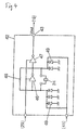
- Fig.1 is a block diagram of a crystal oscillation apparatus according to an embodiment of the present invention.
- Fig.2 is a block diagram of a mobile telephone using the crystal oscillation apparatus of Fig.1.
- Fig.3 is a perspective view of a TCXO exploded used in the crystal oscillation apparatus of Fig.1.
- Fig.4 is a block diagram of a voltage control crystal oscillating circuit used in the crystal oscillation apparatus of Fig.1.
- Fig.5 is a circuit diagram of an amplifier used in the crystal oscillation apparatus of Fig.1.
- Fig.6 is a circuit diagram of an adder and a sample hold circuit used in the crystal oscillation apparatus of Fig.1.
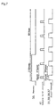
- Fig.7 is a time chart showing the operating condition of key part of the crystal oscillation apparatus of Fig.1.
- Fig.8 is a memory map of a memory device used in the crystal oscillation apparatus of Fig.1.
- Fig.9 is a chart showing the control voltage applied to baractor diode of a voltage control crystal oscillating circuit used in the crystal oscillation apparatus of Fig.1.
- Fig.10 is a chart showing the voltage applied to baractor diode of a voltage control crystal oscillating circuit, and the oscillation frequency in the crystal oscillation apparatus of Fig.1.
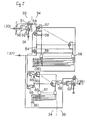
- Fig.2 is a block diagram of a mobile telephone; where numeral 1 denotes an antenna, provided between the antenna 1 and a receiver 2 are, from antenna 1, an antenna commoner 3, an amplifier 4, a band pass filter 5, a mixer 6, a band pass filter 7, a mixer 8, band pass filter 9, a demodulator 10, and a receiving signal processing circuit 11.
- a transmitter 12 and the antenna commoner 3 Provided between a transmitter 12 and the antenna commoner 3 are, from transmitter 12, a transmitting signal processing circuit 13, a modulator 14, a band pass filter 15, a power amplifier 16, and an isolator 17.
- the mixer 6 is coupled with a VCO/synthesizer 19 via band pass filter 18, the VCO/synthesizer 19 is coupled also with the modulator 14.
- TCXO temperature compensation type crystal oscillating circuit
- a signal generated at TCXO 21 is gradually doubled at VCO/synthesizer 19, which is supplied via band pass filter 18 to mixer 6 of receiving system, at the same time direct to modulator 14.
- VCO/synthesizer 19 is supplied via band pass filter 18 to mixer 6 of receiving system, at the same time direct to modulator 14.
- TCXO 21 The constitution of TCXO 21 in the present embodiment is shown in Fig.1 and Fig.3.
- numeral 23 denotes a base board.
- base board 23 On top of which base board 23, a crystal oscillator 24 and a semiconductor integrated circuits(hereinafter referred to as IC) 25 are mounted, and are covered and hermetically sealed with a metal case 26 covering the base board 23.
- IC 25 is as shown in Fig.1 coupled at its Vcc terminal 27 with a batrery 23 of mobile telephone shown in Fig.2.
- the Vcc terminal 27 is coupled also with a power source regulator 29 for stabilizing the power supply.
- the power source regulator 29 is for supplying stable electricity to each of the parts shown in Fig.1.
- a temperature sensor 30 built within the IC 25 is coupled with an amplifier 31 and a temperature detecting section 32, and supplies the detected temperature signal to the both.
- the temperature sensor 30 is comprised of a semiconductor diode, whose resistance value linearly decreases along with the temperature going from the low to high, thereby the output voltage shows a linear decrease.
- the amplifier 31 is comprised of a polarity reversing circuit 33, a variable attenuator 34, and an amplifying circuit 35.
- the polarity reversing circuit 33 is coupled with temperature sensor 30.
- the variable attenuator 34 is coupled with polarity reversing circuit 33, memory 36, and second D/A converter 37.
- the amplifying circuit 35 is coupled with memory 36 and variable attenuator 34. Between memory 36 and temperature detecting circuit 32, the first D/A converter 38 is intervening.
- An adder 39 is coupled with the amplifying circuit 35 of amplifier 31.
- the adder 39 is coupled via Vc terminal 40 with the control circuit 20 of mobile telephone shown in Fig.2.
- the output of adder 39 is supplied via sample hold circuit 41 to voltage control crystal oscillating circuit 42, the output of voltage control crystal oscillating circuit 42 is supplied via Vout terminal 43 to VCO/synthesizer 19 shown in Fig.2.
- numeral 44 denotes a power supply control section for intermittently operating the TCXO 21, which will be described later in detail, and 45 is a grounding terminal.
- a temperature detection data among the 8 control voltage setting groups stored in memory 36 is supplied via first D/A converter 38 to temperature detecting section 32 one after another as a second signal; and the first and the second signals are compared there.
- a stabilized DC voltage is supplied from the power source regulator 29 of Fig.1 to amplifying circuits 46, 47.
- An oscillating circuit is constituted with amplifying circuit 46 and resistor 48 connected in parallel, and a crystal oscillator 24 is oscillated by the oscillating circuit.
- the oscillation output is supplied via amplifying circuit 47 and Vout terminal 43 to VCO/synthesizer 19 of Fig.2.
- a plurality of varactor diodes 49 provided as frequency adjusting element to both input and output sides of the crystal oscillator 24 adjust the oscillation frequency.
- the capacitance of these baractor diodes 49 is adjusted in accordance with the level of DC voltage applied to the cathode of baractor diodes 49 via sample hold circuit 41 of Fig.1. Thereby the oscillation frequency is adjusted.
- the overall capacitance of plural varactor diodes 49 disposed at the input side of crystal oscillator 24 is made to be equal to or larger than the overall capacitance of plural baractor diodes 49 disposed at the output side. The reason is for reducing the power consumption; if the capacitance at output side is larger, a larger current readily flows resulting in a large power consumption.
- the amplifier 31 is comprised of polarity reversing circuit 33, variable attenuator 34, and amplifying circuit 35, connected in series, details of which are shown in Fig.5.
- the polarity reversing circuit 33 is comprised of an amplifying circuit 50 and two switching devices 51, 52. Each of the switching devices 51, 52 makes opposite switching action to each other, the amplification ratio of amplifying circuit 50 is 1, and the output of temperature sensor 30 is delivered to the reversal input terminal of the amplifying circuit 50.
- the ON and OFF operation of said switching devices 51, 52 is determined by digital data supplied from memory 36.
- an output from temperature sensor 30 bypasses the amplifying circuit 50 to be delivered as it is to variable attenuator 34 via switching device 51.
- variable attenuator 34 thus receiving the output from polarity reversing circuit 33 is for controlling the graduation by producing a preliminary graduation taking into account the eventual graduation to be obtained after amplification by the amplifying circuit 35.
- the variable attenuator 34 comprises 16 pcs of resistors 54 connected in series, and a plurality of switching devices 57, 58, two respective pcs of which form one set of switch, for guiding the voltage between the ends of a selected resistor 54 to amplifying circuits 55, 56; wherein the selected switching devices 57, 58 are held ON at a same time.
- a couple of switching devices 57, 58 is determined depending on which NAND element 59, among several such elements, was selected by a digital data supplied from memory 36.
- resistors 60 are connected in series for 16 pcs. As to which top end of resistors 60 is selected depends on which NAND element 61, among several such elements, was selected by a digital data supplied from memory 36. The top end voltage of selected resistor 60 is supplied to an amplifying circuit 62.
- a primary selection of voltage e.g. 8/16 V and 7/16 V
- a secondary voltage selection viz which voltage value between 8/16 V and 7/16 V is to be selected, is performed by the selection of a resistor 60 among the 16 pcs.
- amplfying circuit 53 As the amplification ratio of amplfying circuit 53 is fixed at e.g. 20times, said output from amplifying circuit 62 inputted at the reversal input terminal is delivered as the output of -20 times. Thus, the graduation, polarity of which is fixed at said polarity reversing circuit 33, is set in this amplifying circuit 53.
- an analogue voltage is supplied from second D/A converter 37; the analogue voltage makes itself the offset voltage.
- the voltage whose polarity, graduation and offset are thus controlled at amplifier 31 is delivered to an adder 39.
- the constitution of adder 39 is as shown in Fig.6.
- the output from amplifier 31 of Fig.5 is supplied to the reversal input terminal of amplifying circuits 63, 64, having a xl amplification; in a case when the oscillation frequency is shifted due to aging or other factors, a DC voltage is supplied to Vc terminal 40 from control circuit 20 of a mobile telephone of Fig.2.
- a comparator 65 watches whether or not a DC voltage lower or higher than a specified value is delivered from the control circuit 20; when such voltage is supplied to the reversal input terminal, an OFF state is produced. Then a switching device 66 is turned ON, and 67 OFF. As a result, said DC voltage that is lower or higher than a specified value is supplied to the non-reversal input terminal of amplifying circuit 64; in a case when said lower voltage is supplied to the terminal, the voltage to be supplied to cathode of varactor diode 49 of Fig.4 drops and the capacitance increases, and the oscillation frequency is lowered.
- the adder 39 prevents the shift of oscillation frequency due to aging or other causes.
- the sample hold circuit 41 is comprised of an amplifying circuit 68, a capacitor 69 connected to the non-reversal input terminal of the amplifying circuit, a switching device 70 provided at the input side, etc.
- the switching device 70 is repeated to open and close intermittently by the power supply control section 44 shown in Fig.1; close for 10ùsec, open for 310ùsec, as shown in Fig.7.
- While closing, the capacitor 69 is charged upto a DC voltage level set by each of the conditions hitherto established, and the DC voltage value to be supplied to the cathode of baractor diode 49 is determined by the the level of charging.
- the switching device 70 is opened the voltage charged in capacitor 69 decreases due to the self discharge. Therefore, the switching device 70 is closed again in 310ùsec for charging.
- the power supply control section 44 instructs to suspend power supply to all the amplifiers 31, adder 39, and first and second D/A converters 38, 37. This is intended to save the energy.
- the memory 36 repeats predetermined routine execution. Energy consumption is saved by the power supply control section 44 through the intermittent power supply to memory 36.
- the 2.56msec is made as the time for power supply to memory 36, while the suspension time is set to be lOsec.
- the memory 36 is comprised of EEPROM, whose data are rewritable.
- control voltage setting groups each group consisting of 4 bytes, in memory 36, as shown in Fig.8.
- a temperature detection data is memorized in the 1st byte, a graduation setting data in the 2nd byte, a graduation setting data in the 3rd byte, and an offset voltage data in the 4th byte.
- the first control voltage setting group represents a first, from low temperature side towards high temperature side, linear control voltage(containting the polarity, graduation and offset voltage), the second control voltage setting group a second towards the high temperature side, the third control voltage setting group a third towards the high temperature side, the fourth control voltage setting group a fourth towards the high temperature side, the fifth control voltage setting group a fifth towards the high temperature side, the sixth control voltage setting group a sixth towards the high temperature side, the seventh control voltage setting group a seventh towards the high temperature side, and the eighth control voltage setting group an eighth towards the high temperature side; in this constitution, however, depending on the characteristics of crystal oscillator 24, the temperature compensation from the low temperature towards high temperature side may be completed without using the entire control voltage setting groups upto the eighth group.
- the greatest feature with the present embodiment is that the temperature compensation covering from the low to high temperature range can be linear-approximated using a number of the linear control voltages, eight at the most.
- a case 26 is attached on a board 23 as shown in Fig.3 to hermetically seal-in an IC 25 and a crystal oscillator 24, then these members as they are put into a thermostatic chamber to write data in the memory there.
- the switching device 70 of Fig.6 is kept open.
- thermostatic chamber The temperature of thermostatic chamber is raised from -30°C gradually to 80°C; meanwhile, at each 10°C, DC voltage is applied on baractor diode 49 via capacitor 69 and amplifying circuit 68 of Fig.6.
- the first (from the low temperature) straight line of linear control voltage line T covers a region from -30°C to -12°C, making a straight voltage control line connecting from 3.45V to 2.54V.
- the second line covers from -12°C to +9°C, making a straight voltage control line connecting from 2.54V to 2.33V.
- the third line covers from 9°C to 43°C, making a straight voltage control line connecting from 2.33V to 2.55V.
- the fourth line covers from 43°C to 63°C, making a straight voltage control line connecting from 2.55V to 2.35V.
- the fifth line covers from 63°C to 80°C, making a straight voltage control line connecting from 2.35V to 1.65V.
- the above described data corresponding to each of the 5 straight voltage control lines are written respectively in the first to fifth control voltage setting groups of memory 36, as the temperature detection data, graduation setting data, and offset voltage data.
- a line L in Fig.10 represents shifting frequency of the oscillation when the above described control voltage was not applied to.
- the line H of present embodiment is compared with the line L, it may be understood that the accuracy of invented apparatus is extremely high despite the fact that it is obtained through a linear approximation with 5 straight control voltage lines.
- the temperature detection data of each control voltage setting group in memory 36 is converted into DC voltage at the first D/A converter 38 of Fig.1, and then supplied to temperature detecting section 32 to be compared with the present temperature detected by temperature sensor 30.
- the temperature sensor is comprised of semiconductor diode, the output voltage linearly decreases along with the increasing temperature.
- the graduation setting data and offset voltage data of corresponding control voltage setting group in memory 36 are read out.
- the graduation setting data is supplied to polarity reversing circuit 33 and variable attenuator 34 in amplifier 31 of Fig.5.
- the offset voltage data is supplied to variable attenuator 34 and amplifying circuit 35 of Fig.5 via second D/A converter 37, as described already.
- the present embodiment conducts a straight line approximation with linear control voltages numbering not more than 8. This is based on new findings that among the voltage control crystal oscillating circuits each one circuit has its own shape of control voltage zone (shown in Fig.9), different to each other, and that despite the above fact the high precision control as accurate as ⁇ 1PPM is implementable with linear control voltages counting as many as 8.
- the invented apparatus comprises a crystal oscillating circuit, a frequency adjusting elememt electrically coupled with the crystal oscillating circuit, and a control circuit for controlling the voltage to be applied to the frequency adjusting element;
- said control circuit comprises a temperature sensor, a temperature detecting section electrically coupled with the temperature sensor, a memory device electrically coupled with the temperature detecting section, an amplifier to which the memory device and said temperature sensor are electrically coupled, a first D/A converter electrically intervening between said memory device and temperature detecting section, a second D/A converter electrically intervening between said memory device and amplifier;
- said memory device comprises actually-operative control voltage setting groups counting not more than 8 units, each of the control voltage setting groups has in the memory a temperature detection data, amplitude setting data, and an offset voltage data.
- the memory contains not more than actually-operative 8 control voltage setting groups, each of which groups is comprised of temperature detection data, amplitude setting data and offset voltage data. Therefore, a memory device of smaller memory capacity is suffice, and a simpler control circuit can control memories of not more than 8 actually-operative control voltage setting groups, as a result the size of semiconductor integrated circuits containing the memory and control circuit can be made smaller.
- the smaller memory and the simpler control circuit can work on a smaller power consumption.
Landscapes
- Chemical & Material Sciences (AREA)
- Crystallography & Structural Chemistry (AREA)
- Oscillators With Electromechanical Resonators (AREA)
- Stabilization Of Oscillater, Synchronisation, Frequency Synthesizers (AREA)
Description
Claims (14)
- A crystal oscillation apparatus comprising:a crystal oscillating circuit (42) having a crystal resonator (24) and a frequency adjusting element (49) electrically coupled with the crystal resonator; andcontrol circuitry for controlling a voltage to be applied to said frequency adjusting element; wherein said control circuitry comprises:a temperature sensor (30);memory means (36) having stored therein no more than eight sets of control data and temperature data according to the temperature range to which each said set is applicable; anddigital-to-analog conversion means (37) arranged to convert control data from said memory means into an analog signal; characterised by further comprising:further digital-to-analog conversion means (38) arranged to convert said temperature data into a further analog signal;a temperature detecting section (32) arranged to compare the output of said temperature sensor (30) with the output of said further digital-to-analog conversion means (38) to determine the temperature range corresponding to the output of said temperature sensor (30) to select the one of said sets of control data corresponding to the determined temperature range; andamplifier means (31) arranged to output a compensation signal to said frequency adjusting element (49) according to the output from said temperature sensor and said first mentioned analog signal input thereto, which analog signal corresponds to the selected control data which specifies compensating amplification and offset values.
- The crystal oscillation apparatus of claim 1 wherein at least one of the amplifier means, first mentioned and further digital-to-analog conversion means, temperature detecting section and memory means performs an intermittent operation.
- The crystal oscillation apparatus of claim 2 wherein the pause time of intermittent operation in at least one of the amplifier means, first mentioned and further digital-to-analog conversion means and temperature detecting section is shorter than the pause time of intermittent operation with memory means.
- The crystal oscillation apparatus of claim 1 wherein the amplifier means (31) comprises a variable attenuator (34) and an amplifying circuit (35).
- The crystal oscillation apparatus of claim 4 wherein the lowest level of output from the variable attenuator is set at a voltage not lower than 0.
- The crystal oscillation apparatus of claim 1 wherein the first mentioned and further digital-to-analog conversion means comprise a variable attenuator.
- The crystal oscillation apparatus of claim 6 wherein the lowest level of output from the variable attenuator is set at a voltage not lower than 0.
- The crystal oscillation apparatus of claim 1 wherein the frequency adjusting element comprises a plurality of varactor diodes, which varactor diodes being electrically coupled with the input side and the output side of the crystal resonator.
- The crystal oscillation apparatus of claim 8 wherein the capacitance of input side varactor diode is equal to or higher than that of output side varactor diode.
- The crystal oscillation apparatus of claim 8 wherein the number of varactor diodes to be electrically coupled with the input and output sides of crystal resonator is selected according to oscillation frequency of the crystal oscillating circuit.
- The crystal oscillation apparatus of claim 1 wherein an open circuit switch is provided between the amplifier means (31) and the frequency adjusting element (49), and an external voltage input terminal (40) is electrically coupled between the open circuit switches (66,67) and the frequency adjusting element.
- The crystal oscillation apparatus of claim I wherein the frequency adjusting element and the control circuitry are constituted within a single semiconductor device (25).
- A crystal oscillation apparatus according to claim 1, 2 or 3, further comprising:a sample hold circuit (41) between said frequency adjusting element and amplifier means.
- A method of adjusting a crystal oscillation apparatus according to any preceding claim comprising the steps of:(1) putting the crystal oscillation apparatus into thermostatic chamber with the circuit between amplifier means and frequency adjusting element open,(2) varying the temperature of thermostatic chamber from low to high for finding the upper and the lower limits of a band of control voltages by which the oscillation frequency of crystal oscillating circuit falls within a specified range of tolerance, by applying control voltage on said frequency adjusting element at each of specified temperature zones, and(3) connecting from said low temperature through high temperature with straight lines counting not more than 8, so as falling within said band of control voltages covering said low to high temperatures found out in the above stop (2), and writing the data produced by each of the straight lines counting not more than 8 and outputs of the temperature sensor covering from said low temperature through high temperature into the memory means as the temperature detection data, amplitude setting data and offset voltage data corresponding to respective straight lines.
Applications Claiming Priority (4)
| Application Number | Priority Date | Filing Date | Title |
|---|---|---|---|
| JP8933195 | 1995-04-14 | ||
| JP7089331A JPH08288741A (en) | 1995-04-14 | 1995-04-14 | Crystal oscillator and its adjustment method |
| JP89331/95 | 1995-04-14 | ||
| PCT/JP1995/001285 WO1996032775A1 (en) | 1995-04-14 | 1995-06-28 | Quartz oscillator device and its adjusting method |
Publications (3)
| Publication Number | Publication Date |
|---|---|
| EP0766376A1 EP0766376A1 (en) | 1997-04-02 |
| EP0766376A4 EP0766376A4 (en) | 1998-08-26 |
| EP0766376B1 true EP0766376B1 (en) | 2002-09-18 |
Family
ID=13967710
Family Applications (1)
| Application Number | Title | Priority Date | Filing Date |
|---|---|---|---|
| EP95923533A Expired - Lifetime EP0766376B1 (en) | 1995-04-14 | 1995-06-28 | Quartz oscillator device and its adjusting method |
Country Status (8)
| Country | Link |
|---|---|
| US (1) | US5801594A (en) |
| EP (1) | EP0766376B1 (en) |
| JP (1) | JPH08288741A (en) |
| KR (1) | KR100235399B1 (en) |
| CN (1) | CN1063889C (en) |
| CA (1) | CA2192987C (en) |
| DE (1) | DE69528265T2 (en) |
| WO (1) | WO1996032775A1 (en) |
Families Citing this family (43)
| Publication number | Priority date | Publication date | Assignee | Title |
|---|---|---|---|---|
| JP3543493B2 (en) * | 1996-06-07 | 2004-07-14 | 株式会社デンソー | Electronic circuit operation characteristics correction device |
| KR100290498B1 (en) * | 1996-12-17 | 2001-06-01 | 지니 엠. 데이비스 | Temperature Compensation Circuit for Crystal Oscillator and Manufacturing Method Thereof |
| US5760656A (en) * | 1996-12-17 | 1998-06-02 | Motorola Inc. | Temperature compensation circuit for a crystal oscillator and associated circuitry |
| JP2984614B2 (en) * | 1997-01-24 | 1999-11-29 | 日本電気アイシーマイコンシステム株式会社 | Intermittent reception system for mobile communication devices |
| CA2294861C (en) | 1997-07-11 | 2005-12-06 | Matsushita Electric Industrial Co., Ltd. | Function generation circuit, crystal oscillation device, and method of adjusting the crystal oscillation device |
| US6052036A (en) * | 1997-10-31 | 2000-04-18 | Telefonaktiebolaget L M Ericsson | Crystal oscillator with AGC and on-chip tuning |
| FR2770946A1 (en) * | 1997-11-12 | 1999-05-14 | Motorola Semiconducteurs | Crystal oscillator with temperature compensation |
| US6160458A (en) * | 1998-03-23 | 2000-12-12 | Dallas Semiconductor Corporation | Temperature compensated crystal oscillator |
| US5994970A (en) * | 1998-03-23 | 1999-11-30 | Dallas Semiconductor Corporation | Temperature compensated crystal oscillator |
| JP3358619B2 (en) * | 1999-12-06 | 2002-12-24 | セイコーエプソン株式会社 | Temperature compensated oscillator, method of controlling temperature compensated oscillator, and wireless communication device |
| US6388532B1 (en) * | 2000-02-15 | 2002-05-14 | Cardinal Components, Inc. | System and method for programming oscillators |
| GB2360404B (en) | 2000-03-17 | 2004-03-10 | Ericsson Telefon Ab L M | Electronic circuit |
| US6545550B1 (en) | 2000-07-17 | 2003-04-08 | Marvin E. Frerking | Residual frequency effects compensation |
| US6853259B2 (en) * | 2001-08-15 | 2005-02-08 | Gallitzin Allegheny Llc | Ring oscillator dynamic adjustments for auto calibration |
| US7098748B2 (en) * | 2001-09-21 | 2006-08-29 | Schmidt Dominik J | Integrated CMOS high precision piezo-electrically driven clock |
| KR100426663B1 (en) * | 2001-12-26 | 2004-04-14 | 신성전자공업 주식회사 | An equilibrated OCXO at room temperature and its control process |
| US7791424B2 (en) | 2002-10-15 | 2010-09-07 | Marvell World Trade Ltd. | Crystal oscillator emulator |
| US7042301B2 (en) | 2002-10-15 | 2006-05-09 | Marvell International Ltd. | Crystal oscillator emulator |
| US7253495B2 (en) | 2002-10-15 | 2007-08-07 | Marvell World Trade Ltd. | Integrated circuit package with air gap |
| US7148763B2 (en) | 2002-10-15 | 2006-12-12 | Marvell World Trade Ltd. | Integrated circuit including processor and crystal oscillator emulator |
| US7760039B2 (en) | 2002-10-15 | 2010-07-20 | Marvell World Trade Ltd. | Crystal oscillator emulator |
| US7768360B2 (en) | 2002-10-15 | 2010-08-03 | Marvell World Trade Ltd. | Crystal oscillator emulator |
| EP1429451A1 (en) * | 2002-12-11 | 2004-06-16 | Dialog Semiconductor GmbH | High quality Parallel resonance oscillator |
| US7164325B2 (en) * | 2004-03-30 | 2007-01-16 | Qualcomm Incorporated | Temperature stabilized voltage controlled oscillator |
| FR2874777B1 (en) * | 2004-09-02 | 2007-01-05 | Sagem | MOBILE TELEPHONE AND METHOD OF USING THE MOBILE PHONE |
| JP2006133056A (en) * | 2004-11-05 | 2006-05-25 | Nec Electronics Corp | Semiconductor device and semiconductor element |
| CN100473995C (en) * | 2005-03-02 | 2009-04-01 | 欧阳槐清 | Testing regulating device and method of quartz crystal osciuator |
| JP4108695B2 (en) * | 2005-07-15 | 2008-06-25 | 三菱電機株式会社 | In-vehicle electronic control unit |
| US7852098B2 (en) | 2005-08-01 | 2010-12-14 | Marvell World Trade Ltd. | On-die heating circuit and control loop for rapid heating of the die |
| US7375597B2 (en) | 2005-08-01 | 2008-05-20 | Marvell World Trade Ltd. | Low-noise fine-frequency tuning |
| JP4316591B2 (en) * | 2005-08-01 | 2009-08-19 | マーベル ワールド トレード リミテッド | Low noise and fine frequency adjustment |
| US7872542B2 (en) | 2005-08-01 | 2011-01-18 | Marvell World Trade Ltd. | Variable capacitance with delay lock loop |
| JP4895690B2 (en) | 2006-06-01 | 2012-03-14 | パナソニック株式会社 | Function generation circuit |
| US20080068107A1 (en) * | 2006-09-06 | 2008-03-20 | Luich Thomas M | High performance, flexible programmable clock circuit |
| JP5073351B2 (en) * | 2007-04-12 | 2012-11-14 | 日本電波工業株式会社 | Electronic devices for surface mounting |
| JP4524326B2 (en) * | 2008-05-13 | 2010-08-18 | 日本電波工業株式会社 | Crystal oscillator |
| RU2439775C1 (en) * | 2010-07-19 | 2012-01-10 | Юрий Станиславович Гуськов | High-frequency quartz oscillator |
| JP5776884B2 (en) * | 2011-04-18 | 2015-09-09 | セイコーエプソン株式会社 | Temperature compensated oscillation circuit, electronic equipment |
| JP5787068B2 (en) * | 2011-05-13 | 2015-09-30 | セイコーエプソン株式会社 | Temperature compensated oscillation circuit, electronic equipment |
| JP2016005118A (en) * | 2014-06-17 | 2016-01-12 | セイコーエプソン株式会社 | Oscillation circuit, oscillator, electronic device, and moving object |
| JP2016134738A (en) | 2015-01-19 | 2016-07-25 | セイコーエプソン株式会社 | Oscillator, electronic apparatus and mobile |
| JP6665408B2 (en) * | 2015-02-18 | 2020-03-13 | セイコーエプソン株式会社 | Oscillation circuit, electronic device, moving object, and adjustment method of oscillation circuit |
| US10171033B2 (en) * | 2016-11-03 | 2019-01-01 | Intel Corporation | Crystal oscillator interconnect architecture with noise immunity |
Family Cites Families (15)
| Publication number | Priority date | Publication date | Assignee | Title |
|---|---|---|---|---|
| US3719838A (en) * | 1971-08-02 | 1973-03-06 | Bulova Watch Co Inc | Temperature compensating digital system for electromechanical resonators |
| FR2469823A1 (en) * | 1979-11-09 | 1981-05-22 | Thomson Csf | Temperature stable frequency generator for frequency synthesiser - uses control voltage, based on spot frequency characteristics, calculated from digital processor |
| JPS57172426A (en) * | 1981-04-17 | 1982-10-23 | Shimadzu Corp | Optional function generator |
| JPS5933906A (en) * | 1982-08-19 | 1984-02-24 | Nec Corp | Crystal oscillator |
| JPS59109975A (en) * | 1982-12-14 | 1984-06-25 | Mitsubishi Electric Corp | Function generating device |
| JPS61216026A (en) * | 1985-03-20 | 1986-09-25 | Nec Corp | Generating circuit for approximate function value |
| JPS6238605A (en) * | 1985-08-13 | 1987-02-19 | Nec Corp | Crystal oscillator |
| US4727340A (en) * | 1986-04-30 | 1988-02-23 | Tektronix, Inc. | Comb generators |
| US4746879A (en) * | 1986-08-28 | 1988-05-24 | Ma John Y | Digitally temperature compensated voltage-controlled oscillator |
| DE3629588A1 (en) * | 1986-08-30 | 1988-03-03 | Franz Dipl Ing Leitl | CRYSTAL OSCILLATOR COMPENSATION CIRCUIT |
| JP2736431B2 (en) * | 1988-03-03 | 1998-04-02 | モトローラ・インコーポレーテッド | Crystal oscillator temperature compensation circuit |
| US5081431A (en) * | 1990-01-26 | 1992-01-14 | Nihon Dempa Kogyo Co., Ltd. | Digital temperature-compensated oscillator |
| US5126699A (en) * | 1991-09-27 | 1992-06-30 | Allied-Signal Inc. | Digitally compensated modulation system for frequency synthesizers |
| US5473289A (en) * | 1993-01-25 | 1995-12-05 | Matsushita Electric Industrial Co., Ltd. | Temperature compensated crystal oscillator |
| US5548252A (en) * | 1993-12-07 | 1996-08-20 | Kabushiki Kaisha Meidensha | Digital temperature compensated crystal oscillator |
-
1995
- 1995-04-14 JP JP7089331A patent/JPH08288741A/en active Pending
- 1995-06-28 KR KR1019960707137A patent/KR100235399B1/en not_active Expired - Fee Related
- 1995-06-28 WO PCT/JP1995/001285 patent/WO1996032775A1/en not_active Ceased
- 1995-06-28 US US08/750,827 patent/US5801594A/en not_active Expired - Fee Related
- 1995-06-28 EP EP95923533A patent/EP0766376B1/en not_active Expired - Lifetime
- 1995-06-28 CA CA002192987A patent/CA2192987C/en not_active Expired - Fee Related
- 1995-06-28 CN CN95193377A patent/CN1063889C/en not_active Expired - Fee Related
- 1995-06-28 DE DE69528265T patent/DE69528265T2/en not_active Expired - Fee Related
Also Published As
| Publication number | Publication date |
|---|---|
| DE69528265T2 (en) | 2003-01-23 |
| EP0766376A1 (en) | 1997-04-02 |
| CA2192987A1 (en) | 1996-10-17 |
| KR100235399B1 (en) | 1999-12-15 |
| CN1149940A (en) | 1997-05-14 |
| EP0766376A4 (en) | 1998-08-26 |
| CA2192987C (en) | 2005-01-04 |
| CN1063889C (en) | 2001-03-28 |
| JPH08288741A (en) | 1996-11-01 |
| KR970704266A (en) | 1997-08-09 |
| DE69528265D1 (en) | 2002-10-24 |
| WO1996032775A1 (en) | 1996-10-17 |
| US5801594A (en) | 1998-09-01 |
Similar Documents
| Publication | Publication Date | Title |
|---|---|---|
| CA2192987C (en) | Quartz oscillator device and its adjusting method | |
| US5473289A (en) | Temperature compensated crystal oscillator | |
| EP1025635B1 (en) | Crystal oscillator with agc and on-chip tuning | |
| EP0248589B1 (en) | Temperature-compensated oscillator circuit | |
| KR20020003393A (en) | Temperature-compensated crystal oscillator and method of temperature compensation | |
| KR20000057646A (en) | Temperature compensation circuit for a crystal oscillator | |
| US5021749A (en) | Switchable capacitor loop filter for phase locked loop | |
| US5874864A (en) | Crystal oscillating device and method of adjusting said crystal oscillating device | |
| EP0741930A1 (en) | Low power temperature compensated crystal oscillator | |
| KR20000073779A (en) | Digital temperature compensated crystal oscillator using temperature adaptive capacitor array | |
| US5363057A (en) | Control device for power amplifier | |
| US4223524A (en) | Quartz oscillation circuit for electronic timepieces | |
| JP3253207B2 (en) | Temperature compensated crystal oscillator | |
| JP2736431B2 (en) | Crystal oscillator temperature compensation circuit | |
| KR100691346B1 (en) | Oscillator and its compensation method | |
| JPH09102713A (en) | Crystal oscillation device and adjustment method thereof | |
| JPH0998022A (en) | How to adjust the crystal oscillator | |
| US5384553A (en) | Voltage control oscillation circuit | |
| EP0453083A1 (en) | An asynchronous delay circuit | |
| EP1328981A1 (en) | Universal temperature compensation application specific integrated circuit | |
| KR100280926B1 (en) | Voltage controlled oscillation circuit | |
| JP3911722B2 (en) | Analog / digital input / output switch circuit | |
| KR100190640B1 (en) | Digital temperature compensating oscillator enable to connect various crystal | |
| JPH1093344A (en) | Temperature compensation data writing method for oscillator | |
| JPS62102609A (en) | Oscillation circuit |
Legal Events
| Date | Code | Title | Description |
|---|---|---|---|
| PUAI | Public reference made under article 153(3) epc to a published international application that has entered the european phase |
Free format text: ORIGINAL CODE: 0009012 |
|
| 17P | Request for examination filed |
Effective date: 19961216 |
|
| AK | Designated contracting states |
Kind code of ref document: A1 Designated state(s): DE FR GB |
|
| A4 | Supplementary search report drawn up and despatched | ||
| AK | Designated contracting states |
Kind code of ref document: A4 Designated state(s): DE FR GB |
|
| 17Q | First examination report despatched |
Effective date: 19990920 |
|
| GRAG | Despatch of communication of intention to grant |
Free format text: ORIGINAL CODE: EPIDOS AGRA |
|
| GRAG | Despatch of communication of intention to grant |
Free format text: ORIGINAL CODE: EPIDOS AGRA |
|
| GRAH | Despatch of communication of intention to grant a patent |
Free format text: ORIGINAL CODE: EPIDOS IGRA |
|
| GRAH | Despatch of communication of intention to grant a patent |
Free format text: ORIGINAL CODE: EPIDOS IGRA |
|
| GRAA | (expected) grant |
Free format text: ORIGINAL CODE: 0009210 |
|
| AK | Designated contracting states |
Kind code of ref document: B1 Designated state(s): DE FR GB |
|
| REG | Reference to a national code |
Ref country code: GB Ref legal event code: FG4D |
|
| REF | Corresponds to: |
Ref document number: 69528265 Country of ref document: DE Date of ref document: 20021024 |
|
| ET | Fr: translation filed | ||
| PG25 | Lapsed in a contracting state [announced via postgrant information from national office to epo] |
Ref country code: GB Free format text: LAPSE BECAUSE OF NON-PAYMENT OF DUE FEES Effective date: 20030628 |
|
| PLBE | No opposition filed within time limit |
Free format text: ORIGINAL CODE: 0009261 |
|
| STAA | Information on the status of an ep patent application or granted ep patent |
Free format text: STATUS: NO OPPOSITION FILED WITHIN TIME LIMIT |
|
| 26N | No opposition filed |
Effective date: 20030619 |
|
| PG25 | Lapsed in a contracting state [announced via postgrant information from national office to epo] |
Ref country code: DE Free format text: LAPSE BECAUSE OF NON-PAYMENT OF DUE FEES Effective date: 20040101 |
|
| GBPC | Gb: european patent ceased through non-payment of renewal fee |
Effective date: 20030628 |
|
| PG25 | Lapsed in a contracting state [announced via postgrant information from national office to epo] |
Ref country code: FR Free format text: LAPSE BECAUSE OF NON-PAYMENT OF DUE FEES Effective date: 20040227 |
|
| REG | Reference to a national code |
Ref country code: FR Ref legal event code: ST |