EP0766365B1 - Electronic equipment with intelligent battery - Google Patents
Electronic equipment with intelligent battery Download PDFInfo
- Publication number
- EP0766365B1 EP0766365B1 EP95115174A EP95115174A EP0766365B1 EP 0766365 B1 EP0766365 B1 EP 0766365B1 EP 95115174 A EP95115174 A EP 95115174A EP 95115174 A EP95115174 A EP 95115174A EP 0766365 B1 EP0766365 B1 EP 0766365B1
- Authority
- EP
- European Patent Office
- Prior art keywords
- battery
- power supply
- charging
- electronic equipment
- microprocessor
- Prior art date
- Legal status (The legal status is an assumption and is not a legal conclusion. Google has not performed a legal analysis and makes no representation as to the accuracy of the status listed.)
- Expired - Lifetime
Links
Images


Classifications
-
- H—ELECTRICITY
- H02—GENERATION; CONVERSION OR DISTRIBUTION OF ELECTRIC POWER
- H02J—ELECTRIC POWER NETWORKS; CIRCUIT ARRANGEMENTS OR SYSTEMS FOR SUPPLYING OR DISTRIBUTING ELECTRIC POWER; SYSTEMS FOR STORING ELECTRIC ENERGY
- H02J7/00—Circuit arrangements for charging or discharging batteries or for supplying loads from batteries
- H02J7/865—Battery or charger load switching, e.g. concurrent charging and load supply
-
- H—ELECTRICITY
- H02—GENERATION; CONVERSION OR DISTRIBUTION OF ELECTRIC POWER
- H02J—ELECTRIC POWER NETWORKS; CIRCUIT ARRANGEMENTS OR SYSTEMS FOR SUPPLYING OR DISTRIBUTING ELECTRIC POWER; SYSTEMS FOR STORING ELECTRIC ENERGY
- H02J7/00—Circuit arrangements for charging or discharging batteries or for supplying loads from batteries
- H02J7/40—Circuit arrangements for charging or discharging batteries or for supplying loads from batteries characterised by the exchange of charge or discharge related data
- H02J7/44—Circuit arrangements for charging or discharging batteries or for supplying loads from batteries characterised by the exchange of charge or discharge related data between battery management systems and power sources
-
- H—ELECTRICITY
- H02—GENERATION; CONVERSION OR DISTRIBUTION OF ELECTRIC POWER
- H02J—ELECTRIC POWER NETWORKS; CIRCUIT ARRANGEMENTS OR SYSTEMS FOR SUPPLYING OR DISTRIBUTING ELECTRIC POWER; SYSTEMS FOR STORING ELECTRIC ENERGY
- H02J7/00—Circuit arrangements for charging or discharging batteries or for supplying loads from batteries
- H02J7/485—Circuit arrangements for charging or discharging batteries or for supplying loads from batteries with provisions for charging different types of batteries
Definitions
- the invention concerns an electronic equipment containing a microprocessor, memory, a battery pack and a connection to a controllable power supply, the microprocessor containing at least one charging control routine and the battery including nonvolatile memory with parameters for controlling the power supply.
- a voltage is applied to the battery.
- different battery types NiCd - nickelcadmium, NiMH - nickel metal hydride, LIB - lithium ion battery
- the charging may not reach the optimum for each type. Instead different types of batteries should be charged according to individual charging schemes in order to gain optimum capacity and to secure longterm battery operation. Even when always using the same battery type, for optimum performance it may be necessary to control charging e.g. when the charging is interrupted. After replacing the battery into the charging device it is state of the art to restart a new complete charging operation. This may deteriorate the batteries capacity.
- US-PS 5.254.928 discloses a power management system for battery powered computers.
- the system can determine which one of a plurality of battery packs has been coupled to the system.
- the system recalls from storage the recommended charging pattern for the particular battery pack and charges the same at the recommended rate.
- WO 93/19508 discloses a power supply and battery charging system for supplying power to an electrical device and / or to a battery for charging.
- the system comprises a power controller, whereby, regardless of the rate of charge of the battery, a constant current is maintained for charging the battery while the voltage across the device and the battery is allowed to vary.
- an electronic equipment containing a microprocessor, memory, a battery pack and a connection to a controllable power supply
- the microprocessor containing at least one charging control routine and the battery including nonvolatile memory with parameters for controlling the power supply
- the electronic equipment is a mobile telephone having an off mode, a stand-by mode and a supply mode, and in that in the off and stand-by modes the telephone current of the mobile telephone is measured and the power supply is controlled to hold the charge current constant.
- the parameters stored in the nonvolatile memory included in the battery pack contains e. g. information concerning the battery type, the capacity, the criteria for termination of the charging. This information can be read by the microprocessor which controls the charging via the analog controllable power supply.
- batteries are always handled in an optimal way, even when the customers use batterypacks of different type and capacity. This insures a long lifetime and a high performance of the battery. Even future battery types can be recharged in an optimal way by implementing appropriate parameters in the batterypack's memory.
- the electronic equipment is a mobile phone, especially a handheld or a cordless phone.
- the phones microprocessor may be used and the phone can be connected to the analog controllable power supply preferable by a cable or by pin plug connectors or by appropriate contacts.
- the microprocessor controls the power supply to apply appropriate charging current, depending on the type of battery. Additionally under control of the microprocessor the charging is terminated according to the parameters stored in the battery's non-volatile memory.
- a voltage slope and temperature slope are used as terminating criteria.
- additional terminating criteria may be applied like e. g. a maximum voltage or a maximum temperature and a minimum temperature or a maximum charging time. All this and further parameters are stored in the non-volatile memory included in the batterypack.
- the invention is extremely useful as charging can be done also in the standby mode.
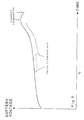
- switching the telephone from off to standby at time t index 1 results in a certain power consumption A index 1 for the standby (STB) mode.
- a index 1 for the standby (STB) mode This would normally result in a decline of battery voltage as shown in fig. 2 (dashed line) and cause termination of charging.
- the current consumed by the telephone is measured continuously and the power supply is controlled to hold the charging current constant as shown in fig. 3.
- the resting voltage is measured.
- the resting voltage is the voltage of the battery for stable capacity (no current flow in the battery).
- the resting voltage is stored and updated in the microprocessor.
- the charging When the phone is to be operated by switching to a supply mode, the charging will be interrupted since the phone for operation needs most of the current delivered by the power supply. The charging shall then be continued from the point where it was stopped as soon as the telephone is returned to standby mode.
- the current from the power supply is controlled to keep the voltage of the battery equal to the resting voltage.
- the power supply gives the necessary energy to the phone. Therefore the customer does not have to disconnect the charging during use in standby or conversation mode.
- a netadapter, a cigarette plug charger or a comfort car kit all controllable
- the customer can use the phone for an unlimited time, even when the battery is completely empty.
Landscapes
- Engineering & Computer Science (AREA)
- Power Engineering (AREA)
- Charge And Discharge Circuits For Batteries Or The Like (AREA)
Description
Claims (2)
- Electronic equipment containing a microprocessor, a memory, a battery pack and a connection to a controllable power supply, the microprocessor containing at least one charging control routine and the battery including nonvolatile memory with parameters for controlling the power supply, characterized in that the electronic equipment is a mobile telephone having an off mode, a stand-by mode and a supply mode, and in that in the off and stand-by modes the telephone current of the mobile telephone is measured and the power supply is controlled to hold the charge current constant.
- Electronic equipment according to claim 1, characterized in that the resting voltage of the battery, at which no current flows in the battery, is measured, stored and continuously updated in the microprocessor and in that during charging, if the mobile telephone is operated by switching to the supply mode, the current from the power supply is controlled to keep the voltage of the battery equal to the resting voltage.
Priority Applications (3)
| Application Number | Priority Date | Filing Date | Title |
|---|---|---|---|
| EP95115174A EP0766365B1 (en) | 1995-09-27 | 1995-09-27 | Electronic equipment with intelligent battery |
| ES95115174T ES2126826T3 (en) | 1995-09-27 | 1995-09-27 | ELECTRONIC EQUIPMENT WITH INTELLIGENT BATTERY. |
| DE69505976T DE69505976T2 (en) | 1995-09-27 | 1995-09-27 | Electronic device with an intelligent battery |
Applications Claiming Priority (1)
| Application Number | Priority Date | Filing Date | Title |
|---|---|---|---|
| EP95115174A EP0766365B1 (en) | 1995-09-27 | 1995-09-27 | Electronic equipment with intelligent battery |
Publications (2)
| Publication Number | Publication Date |
|---|---|
| EP0766365A1 EP0766365A1 (en) | 1997-04-02 |
| EP0766365B1 true EP0766365B1 (en) | 1998-11-11 |
Family
ID=8219653
Family Applications (1)
| Application Number | Title | Priority Date | Filing Date |
|---|---|---|---|
| EP95115174A Expired - Lifetime EP0766365B1 (en) | 1995-09-27 | 1995-09-27 | Electronic equipment with intelligent battery |
Country Status (3)
| Country | Link |
|---|---|
| EP (1) | EP0766365B1 (en) |
| DE (1) | DE69505976T2 (en) |
| ES (1) | ES2126826T3 (en) |
Families Citing this family (3)
| Publication number | Priority date | Publication date | Assignee | Title |
|---|---|---|---|---|
| JP4339423B2 (en) * | 1998-02-13 | 2009-10-07 | ソニー株式会社 | Battery pack, battery system, and charging control method for battery system |
| US6630814B2 (en) | 2000-12-19 | 2003-10-07 | Telefonaktiebolaget Lm Ericsson (Publ) | Method and apparatus for calibrating a rechargeable battery |
| JP4144568B2 (en) | 2004-06-04 | 2008-09-03 | ソニー株式会社 | Battery remaining amount detection system, electronic device and battery pack |
Family Cites Families (5)
| Publication number | Priority date | Publication date | Assignee | Title |
|---|---|---|---|---|
| US5304916A (en) * | 1990-04-11 | 1994-04-19 | Compaq Computer Corporation | Battery charger |
| US5254928A (en) * | 1991-10-01 | 1993-10-19 | Apple Computer, Inc. | Power management system for battery powered computers |
| GB9125446D0 (en) * | 1991-11-29 | 1992-01-29 | Shaye Communications Ltd | Improvements in battery charging |
| CA2132419C (en) * | 1992-03-18 | 1996-12-17 | Gerald L. Brainard | A power supply and battery charging system |
| DE69411991T2 (en) * | 1993-05-05 | 1999-01-21 | Sgs- Thomson Microelectronics (Pte) Ltd., Singapur/Singapore | Power split detector |
-
1995
- 1995-09-27 DE DE69505976T patent/DE69505976T2/en not_active Expired - Lifetime
- 1995-09-27 ES ES95115174T patent/ES2126826T3/en not_active Expired - Lifetime
- 1995-09-27 EP EP95115174A patent/EP0766365B1/en not_active Expired - Lifetime
Also Published As
| Publication number | Publication date |
|---|---|
| EP0766365A1 (en) | 1997-04-02 |
| DE69505976D1 (en) | 1998-12-17 |
| DE69505976T2 (en) | 2000-05-18 |
| ES2126826T3 (en) | 1999-04-01 |
Similar Documents
| Publication | Publication Date | Title |
|---|---|---|
| US8004237B2 (en) | Battery power supply with bidirectional battery charge controller | |
| US5754027A (en) | Battery pack and associated charging system | |
| US6127801A (en) | Battery pack assembly | |
| KR0147033B1 (en) | How to charge the battery | |
| US5738919A (en) | Energy storage system | |
| US3930192A (en) | Stand-by power system | |
| US6709784B2 (en) | Back-up battery for a cellular telephone | |
| EP0925627B1 (en) | Apparatus and method of monitoring battery temperature during charging | |
| JP2001190032A (en) | Power supply control circuit and power supply control method | |
| AU2002236363A1 (en) | Back-up battery for a cellular telephone | |
| JPH09121461A (en) | Self-rechargeable battery and electrical equipment using the same | |
| US6154010A (en) | Battery charging docking cradle for a mobile computer | |
| US6456046B1 (en) | Protection circuit for terminating trickle charge when the battery terminal voltage is greater than a predetermined value | |
| EP0824778B1 (en) | Intelligent battery charging in a hand-held phone | |
| US5793187A (en) | System and method for increasing the available energy in non-rechargeable batteries | |
| JP2000253586A (en) | Charging method for battery and power supply | |
| EP0766365A1 (en) | Electronic equipment with intelligent battery | |
| CA2083813A1 (en) | Battery charging | |
| JP3638369B2 (en) | Secondary battery charging control method | |
| JP3557004B2 (en) | Charging method | |
| JPH10285823A (en) | Device for supplying electric current to electronic devices | |
| EP1921725B1 (en) | Electronic device, including handheld electronic device, with dual battery configuration and associated method | |
| KR19990035608A (en) | Battery charger | |
| JPH08298138A (en) | Charge control method for preventing overcharge | |
| JPH04281332A (en) | Rechargeable battery |
Legal Events
| Date | Code | Title | Description |
|---|---|---|---|
| PUAI | Public reference made under article 153(3) epc to a published international application that has entered the european phase |
Free format text: ORIGINAL CODE: 0009012 |
|
| 17P | Request for examination filed |
Effective date: 19960520 |
|
| AK | Designated contracting states |
Kind code of ref document: A1 Designated state(s): DE ES FR GB IT |
|
| 17Q | First examination report despatched |
Effective date: 19970915 |
|
| GRAG | Despatch of communication of intention to grant |
Free format text: ORIGINAL CODE: EPIDOS AGRA |
|
| GRAG | Despatch of communication of intention to grant |
Free format text: ORIGINAL CODE: EPIDOS AGRA |
|
| GRAH | Despatch of communication of intention to grant a patent |
Free format text: ORIGINAL CODE: EPIDOS IGRA |
|
| GRAH | Despatch of communication of intention to grant a patent |
Free format text: ORIGINAL CODE: EPIDOS IGRA |
|
| GRAA | (expected) grant |
Free format text: ORIGINAL CODE: 0009210 |
|
| AK | Designated contracting states |
Kind code of ref document: B1 Designated state(s): DE ES FR GB IT |
|
| REF | Corresponds to: |
Ref document number: 69505976 Country of ref document: DE Date of ref document: 19981217 |
|
| ITF | It: translation for a ep patent filed | ||
| RAP2 | Party data changed (patent owner data changed or rights of a patent transferred) |
Owner name: TELITAL S.P.A. |
|
| ET | Fr: translation filed | ||
| REG | Reference to a national code |
Ref country code: ES Ref legal event code: FG2A Ref document number: 2126826 Country of ref document: ES Kind code of ref document: T3 |
|
| PLBE | No opposition filed within time limit |
Free format text: ORIGINAL CODE: 0009261 |
|
| STAA | Information on the status of an ep patent application or granted ep patent |
Free format text: STATUS: NO OPPOSITION FILED WITHIN TIME LIMIT |
|
| 26N | No opposition filed | ||
| REG | Reference to a national code |
Ref country code: GB Ref legal event code: IF02 |
|
| PGFP | Annual fee paid to national office [announced via postgrant information from national office to epo] |
Ref country code: ES Payment date: 20080917 Year of fee payment: 14 |
|
| PGFP | Annual fee paid to national office [announced via postgrant information from national office to epo] |
Ref country code: GB Payment date: 20080912 Year of fee payment: 14 |
|
| PGFP | Annual fee paid to national office [announced via postgrant information from national office to epo] |
Ref country code: FR Payment date: 20080926 Year of fee payment: 14 |
|
| GBPC | Gb: european patent ceased through non-payment of renewal fee |
Effective date: 20090927 |
|
| REG | Reference to a national code |
Ref country code: FR Ref legal event code: ST Effective date: 20100531 |
|
| PG25 | Lapsed in a contracting state [announced via postgrant information from national office to epo] |
Ref country code: FR Free format text: LAPSE BECAUSE OF NON-PAYMENT OF DUE FEES Effective date: 20090930 |
|
| PG25 | Lapsed in a contracting state [announced via postgrant information from national office to epo] |
Ref country code: GB Free format text: LAPSE BECAUSE OF NON-PAYMENT OF DUE FEES Effective date: 20090927 |
|
| PG25 | Lapsed in a contracting state [announced via postgrant information from national office to epo] |
Ref country code: IT Free format text: LAPSE BECAUSE OF NON-PAYMENT OF DUE FEES Effective date: 20090927 |
|
| REG | Reference to a national code |
Ref country code: ES Ref legal event code: FD2A Effective date: 20110718 |
|
| PG25 | Lapsed in a contracting state [announced via postgrant information from national office to epo] |
Ref country code: ES Free format text: LAPSE BECAUSE OF NON-PAYMENT OF DUE FEES Effective date: 20110706 |
|
| PGRI | Patent reinstated in contracting state [announced from national office to epo] |
Ref country code: IT Effective date: 20110616 |
|
| PG25 | Lapsed in a contracting state [announced via postgrant information from national office to epo] |
Ref country code: ES Free format text: LAPSE BECAUSE OF NON-PAYMENT OF DUE FEES Effective date: 20090928 |
|
| PGFP | Annual fee paid to national office [announced via postgrant information from national office to epo] |
Ref country code: DE Payment date: 20140922 Year of fee payment: 20 |
|
| PGFP | Annual fee paid to national office [announced via postgrant information from national office to epo] |
Ref country code: IT Payment date: 20140929 Year of fee payment: 20 |
|
| REG | Reference to a national code |
Ref country code: DE Ref legal event code: R071 Ref document number: 69505976 Country of ref document: DE |