EP0766069B1 - Flow tube liner - Google Patents
Flow tube liner Download PDFInfo
- Publication number
- EP0766069B1 EP0766069B1 EP96115559A EP96115559A EP0766069B1 EP 0766069 B1 EP0766069 B1 EP 0766069B1 EP 96115559 A EP96115559 A EP 96115559A EP 96115559 A EP96115559 A EP 96115559A EP 0766069 B1 EP0766069 B1 EP 0766069B1
- Authority
- EP
- European Patent Office
- Prior art keywords
- tube
- grid
- liner
- electrode
- holes
- Prior art date
- Legal status (The legal status is an assumption and is not a legal conclusion. Google has not performed a legal analysis and makes no representation as to the accuracy of the status listed.)
- Expired - Lifetime
Links
- 239000002184 metal Substances 0.000 claims description 47
- 239000012530 fluid Substances 0.000 claims description 14
- 239000000463 material Substances 0.000 claims description 5
- 229920003023 plastic Polymers 0.000 description 9
- 239000004033 plastic Substances 0.000 description 9
- 229920001774 Perfluoroether Polymers 0.000 description 6
- 230000000712 assembly Effects 0.000 description 6
- 238000000429 assembly Methods 0.000 description 6
- 229920001903 high density polyethylene Polymers 0.000 description 5
- 238000005259 measurement Methods 0.000 description 5
- 238000000465 moulding Methods 0.000 description 3
- 229910000831 Steel Inorganic materials 0.000 description 2
- 239000000919 ceramic Substances 0.000 description 2
- 238000000034 method Methods 0.000 description 2
- 230000008569 process Effects 0.000 description 2
- 229910001220 stainless steel Inorganic materials 0.000 description 2
- 239000010935 stainless steel Substances 0.000 description 2
- 239000010959 steel Substances 0.000 description 2
- 230000015572 biosynthetic process Effects 0.000 description 1
- 239000002131 composite material Substances 0.000 description 1
- 150000001875 compounds Chemical class 0.000 description 1
- 238000005260 corrosion Methods 0.000 description 1
- 230000007797 corrosion Effects 0.000 description 1
- 230000008878 coupling Effects 0.000 description 1
- 238000010168 coupling process Methods 0.000 description 1
- 238000005859 coupling reaction Methods 0.000 description 1
- 238000010586 diagram Methods 0.000 description 1
- 238000010438 heat treatment Methods 0.000 description 1
- 238000009413 insulation Methods 0.000 description 1
- 239000012212 insulator Substances 0.000 description 1
- 238000004519 manufacturing process Methods 0.000 description 1
- 230000013011 mating Effects 0.000 description 1
- 230000007246 mechanism Effects 0.000 description 1
- 230000035699 permeability Effects 0.000 description 1
- 239000004810 polytetrafluoroethylene Substances 0.000 description 1
- 229920001343 polytetrafluoroethylene Polymers 0.000 description 1
- 238000004382 potting Methods 0.000 description 1
- 230000002787 reinforcement Effects 0.000 description 1
- 229920002379 silicone rubber Polymers 0.000 description 1
- 238000013020 steam cleaning Methods 0.000 description 1
- 239000000126 substance Substances 0.000 description 1
Images



Classifications
-
- G—PHYSICS
- G01—MEASURING; TESTING
- G01F—MEASURING VOLUME, VOLUME FLOW, MASS FLOW OR LIQUID LEVEL; METERING BY VOLUME
- G01F1/00—Measuring the volume flow or mass flow of fluid or fluent solid material wherein the fluid passes through a meter in a continuous flow
- G01F1/56—Measuring the volume flow or mass flow of fluid or fluent solid material wherein the fluid passes through a meter in a continuous flow by using electric or magnetic effects
- G01F1/58—Measuring the volume flow or mass flow of fluid or fluent solid material wherein the fluid passes through a meter in a continuous flow by using electric or magnetic effects by electromagnetic flowmeters
- G01F1/586—Measuring the volume flow or mass flow of fluid or fluent solid material wherein the fluid passes through a meter in a continuous flow by using electric or magnetic effects by electromagnetic flowmeters constructions of coils, magnetic circuits, accessories therefor
-
- G—PHYSICS
- G01—MEASURING; TESTING
- G01F—MEASURING VOLUME, VOLUME FLOW, MASS FLOW OR LIQUID LEVEL; METERING BY VOLUME
- G01F1/00—Measuring the volume flow or mass flow of fluid or fluent solid material wherein the fluid passes through a meter in a continuous flow
- G01F1/56—Measuring the volume flow or mass flow of fluid or fluent solid material wherein the fluid passes through a meter in a continuous flow by using electric or magnetic effects
- G01F1/58—Measuring the volume flow or mass flow of fluid or fluent solid material wherein the fluid passes through a meter in a continuous flow by using electric or magnetic effects by electromagnetic flowmeters
-
- G—PHYSICS
- G01—MEASURING; TESTING
- G01F—MEASURING VOLUME, VOLUME FLOW, MASS FLOW OR LIQUID LEVEL; METERING BY VOLUME
- G01F1/00—Measuring the volume flow or mass flow of fluid or fluent solid material wherein the fluid passes through a meter in a continuous flow
- G01F1/56—Measuring the volume flow or mass flow of fluid or fluent solid material wherein the fluid passes through a meter in a continuous flow by using electric or magnetic effects
- G01F1/58—Measuring the volume flow or mass flow of fluid or fluent solid material wherein the fluid passes through a meter in a continuous flow by using electric or magnetic effects by electromagnetic flowmeters
- G01F1/584—Measuring the volume flow or mass flow of fluid or fluent solid material wherein the fluid passes through a meter in a continuous flow by using electric or magnetic effects by electromagnetic flowmeters constructions of electrodes, accessories therefor
Definitions
- This invention relates to flow tubes with liners.
- Pipelines and other tubes carrying fluid sometimes include a plastic liner on their inner surface. These liners protect the tube's inner surface from being corroded by the fluid.
- Electromagnetic flowmeters with flow tubes usually require such liners to ensure accurate flow measurement.
- EP-A-0 045 646 discloses an electromagnetic flowmeter interposed between the flanged ends of fluid carrying pipes having a non-magnetic metal spool and a tubular liner disposed within the spool, a cylindrical housing forming an annular inner chamber between the spool and the housing, said inner chamber being filled with a potting compound to seal coils and electrodes therein.
- Patent Abstract of Japan, vol. 09, no. 064 (P-343) and JP-A-59198318 discloses an electromagnetic flowmeter having a reinforcement member perforated with many through holes consisting of two conductive members not contacting each other and immersed in a lining of a measuring pipe.
- EP-A-0 116 875 discloses a non-porous composite electrode, particularly suitable for use in electromagnetic flowmeters. Using of a polymeric material compatible with a polymeric liner of an electromagnetic flowtube allows the electrode to be fused into the liner by application of heat and pressure so as to achieve a seamless interface.
- a magnetic flowmeter has a tube for carrying fluid along a longitudinal axis.
- the tube has faces transverse to the longitudinal axis and disposed at opposite ends of the tube.
- a liner on the inner surface of the tube extends out from an end of the tube and into a recess on one face to anchor the liner in place.
- Preferred embodiments of this aspect include the following features.
- Each face has a circular dovetail recess that extends around the tube.
- the liner extends out from opposite ends of the tube and into the recess on each face.
- the tube has at least one aperture for allowing an electrode to be inserted into the tube in a direction transverse to the longitudinal axis.
- the liner extends up into the aperture at a sufficient thickness to electrically insulate the electrode from the tube and to anchor the liner in place.
- a grid is embedded in the liner, and the liner includes perfluoroalkoxy.
- an electromagnetic flowmeter has a tube for carrying fluid along a longitudinal axis.
- An aperture in a surface of the tube allows an electrode to be inserted into the tube in a direction transverse to the longitudinal axis of the tube.
- a liner is disposed on an inner surface of the tube and comprises a metal grid embedded in a plastic layer.
- the plastic layer and the metal grid have holes aligned with the aperture in the tube.
- the hole in the grid is larger than the hole in the layer so that a portion of the liner near the aperture has no embedded grid.
- a button electrode is inserted through the aperture and holes in the metal grid and layer to hold the portion of the liner against the metal tube.
- Preferred embodiments of this aspect include the following features.
- the grid is a metal perforated cylinder with a spiral seam and is welded to the tube at points on opposite ends of the tube.
- the grid is centered in the tube, and a portion of the layer interposed between the tube and the grid has a constant thickness.
- the button electrode has a head with a face having serrations.
- the serrations are embedded in the portion of the liner to hold the liner in place.
- the layer also extends up into the aperture to hold the liner in place. As a result, the hole in the liner is smaller than the hole in the metal tube.
- the layer that extends up into the aperture is of sufficient thickness to electrically insulate the electrode from the tube.
- the invention features an electromagnetic flowmeter comprising a tube for carrying fluid.
- a liner disposed on an inner surface of the tube includes a perforated cylindrical metal grid embedded in a layer of material.
- the grid has holes in its surface such that lines connecting a center of each of three adjoining holes form an equilateral triangle.
- the invention includes the following features.
- Wires are disposed on an outside surface of the grid and along a longitudinal axis of the grid.
- the wires provide a constant spacing between the grid and the inner surface of the tube.
- Several wires may be disposed parallel to one another on the outside of the cylinder in this manner.
- a diameter of each hole is preferably approximately 3,175 mm (1/8") and a distance between centers of the holes is approximately 4,775 mm (0.188").
- the diameter is 1,588 mm (1/16") and the distance is 2,362 mm (0.093").
- the liner material is resistive to most chemicals and thus protects the inner surface of the tube from corrosion.
- the liner is also highly stable, i.e., it does not buckle, become loose, blister or crack between at least -6,7°C (20°F) and 148,9°C (300°F).
- heating the liner to high temperatures e.g., by routinely steam cleaning the tube, poses no hazard to the liner.
- the stable liner ensures that the inner diameter of the tube remains constant. This is particularly important when the tube is used in a magnetic flowmeter, where changes in the inner diameter of the tube may introduce errors into the flow measurement.
- the stability of the liner is provided in part by the grid which rigidly shapes the liner.
- the grid's rigidity, and in particular, its resistance to compressive stress, is enhanced by its spiral structure and circular cross-section.
- the grid's spiral seam is welded tightly with no gaps to provide additional strength.
- the grid is welded to the tube at several points to help fix the liner in place.
- the grid and liner provide complete (360 degree) coverage of the inner surface of the tube, and thus have no exposed edges or other weak points where the liner may buckle and separate from the inner surface of the tube.
- the constant diameter grid is easily centered in the tube to provide a constant spacing between the grid and the inner surface of the tube.
- Liner material e.g., plastic
- the circular holes in the grid are simple to manufacture and allow the plastic to easily flow through the grid during molding.
- the configuration of the holes (with centers placed on the corners of an equilateral triangle) permits a high concentration of holes per unit of surface area of the grid. This configuration, along with the described optimum size and spacing of the holes, allows the plastic to easily flow through the holes in the grid, without sacrificing the rigidity and strength of the grid.
- the wire welded to the outside of the grid also aids in maintaining a constant spacing between the grid and the tube.
- the wire is disposed parallel to the axis of the tube to provide little friction when the grid is inserted in the tube. As a result, the wire is not likely to detach from the grid during assembly.
- the liner is also held in place by a button electrode inserted through an aperture in the grid into the tube. Serrations on one side of the electrode are embedded into the liner to help hold the liner against the tube.
- the electrode thus provides support to the liner where the grid is cut away to form an aperture and is unable to provide direct support. Extending the liner into the aperture and recesses (or dovetails) on the ends of the tube also contributes to fixing the liner in place.
- an electromagnetic flowmeter 8 has a metal flow tube 10 for transporting fluid along a longitudinal axis (z axis 12).
- the metal tube is placed coaxially between a plastic liner 14 and a tubular housing 16.
- Two magnetic coil assemblies 20, 22 are placed on opposite sides of the flowmeter, either on housing 16 as shown or in between the housing and metal tube 10.
- Two electrode assemblies 24, 25 are mounted in the metal tube through apertures 26, 27 in the housing, tube and plastic liner. Each electrode assembly is spaced from a coil assembly by 90 degrees along the circumference of the metal tube. Both electrode assemblies and coil assemblies are connected to a processor 28.
- processor 28 causes coil assemblies 20, 22 to produce a magnetic field inside the metal tube along x-axis 30, perpendicular to the direction of fluid flow.
- Housing 16 provides a magnetic return path for the magnetic field in the tube.
- Electrodes 24, 25 measure the resulting voltage in the fluid (directed along y-axis 32), and processor 28 converts the voltage measurement to a flow measurement.
- Liner 14 prevents the fluid from corroding the inner surface of the metal tube and thus producing errors in the electrode current measurement.
- a wafer type metal tube 10a with a 38.1 mm (1.5") inner diameter (D) has two opposite flat sections 50, 52 in its outer surface 58 for holding electrode assemblies 24, 25 (Fig. 1). Apertures 26, 27 connect the flat sections to the interior of the metal tube. A typical aperture is 3.81 mm (0.150”) in diameter (diameter d).
- Outer surface 58 (Fig. 3) of metal tube 10a is covered by an insulator, e.g., 0.05 mm (0.002") of PTFE, to prevent shorting to the housing 16 when the flowmeter is fully assembled.
- an insulator e.g., 0.05 mm (0.002") of PTFE
- Inner surface 60 of metal tube 10a has bevels 62, 64 at its two ends for allowing smoother fluid flow into and out of the tube.
- the ends of the tube are flared out to create faces 66, 68 with dovetails 70, 72.
- the faces are connected to flanges 74, 76 (Fig. 2) which allow simple coupling of the tube to fluid carrying conduits.
- Liner 14 is molded against inner surface 60 of the metal tube to provide 360 degrees of coverage (Fig. 1). The only gaps in the liner are aligned with apertures 26, 27 of the tube. Liner 14 also extends out from apertures 26, 27 (at a thickness t of about 0.762 mm (0.03")), and around faces 66, 68 into dovetails 70, 72. Molding the liner into the holes and dovetails helps fix the liner relative to the metal tube.
- Liner 14 contains a metal grid 76 embedded in a perfluoroalkoxy (PFA) layer 78.
- PFA perfluoroalkoxy
- the grid ends before bevels 62, 64 on the tube, i.e., at about 6.35 mm (0.25") from the ends of the tube.
- Each end 79, 80 of the metal grid near the bevels is flared out and welded to the metal tube at four separate points.
- Apertures 82, 84 in the grid are aligned with apertures 26, 27 in metal tube 10a. When the electrodes are inserted into apertures 26, 27, apertures 82, 84 in the grid provide a clearance of 12.7 mm (0.500") between the electrode and the grid.
- grid 76 includes a perforated cylinder of constant diameter.
- the cylinder is preferably formed from 304 annealed steel, with a magnetic permeability of less than or equal to 1.05 and a thickness great enough to support plastic liner 78.
- steel 0.381 mm (0.015") thick is adequate for liner 14 in metal tube 10a.
- Holes 148 in the cylinder surface are arranged such that lines 150 drawn through the centers of the holes form an equilateral triangle, as indicated in Fig. 7. This is accomplished by staggering adjacent rows of holes in the surface of the cylinder. Holes 148 have a diameter of 3.175 mm (0.125”) and are spaced 4.775 mm (0.188”) apart, center to center.
- Stainless steel wires 152 are welded to the outer surface of the cylinder along a longitudinal axis of the cylinder.
- the wires are spaced apart by about one inch along the cylinder's circumference and are each about 0.762 mm (0.03 inch) in diameter. The wires ensure that the grid is properly positioned with respect to the metal tube after assembly, as described in more detail below.
- the cylinder is formed by twisting a strip of perforated stainless steel 154 into a spiral of constant diameter. Spiral seams 156 on the grids are welded together without leaving any gaps. Wires 152 are then welded onto the outside of the grid.
- the plastic liner is mounted on the inside of metal tube 10a as follows. First, grid 76 is inserted in metal tube 10a and welded at opposite ends 79, 80 to the tube (Fig. 4). Wires 152 ensure that the inner wall of the tube and the outer surface of the grid have a constant spacing equal to the diameter of the wires.
- PFA is next molded onto the inner surface of the tube to form plastic layer 78.
- a removable cylindrical mandrel not shown forms the other surface of the mold.
- the PFA flows through the holes in the grid to fill the space between the grid and the inner wall of the metal tube and to form a layer of constant thickness against the inner surface of the grid.
- the PFA also flows up out of apertures 26, 27, and around the faces of the tube into the dovetails 70, 72.
- the plastic layer 78 and grid 76 together form a liner 14 with a constant thickness L of 3.05 mm (0.120").
- the liner is in contact with the inner wall of the metal tube, while grid 76 is spaced 0.635 mm (0.025") from the outer diameter of the liner.
- each electrode assembly 24, 25 includes a button type electrode 200 connected to a lead assembly 202 at one end.
- the electrode has a head 204 at an opposite end with a face 206 for detecting current.
- An opposite face of the head has three serrations 210.
- the electrode is placed in aperture 26 (27) with its head inside the metal tube. Face 206 is thus exposed to the process fluid when the tube is full, and serrations 210 protrude into the liner to help fix both the electrode and the liner in place.
- the portion 14' of liner 14 molded in the aperture separates electrode 200 from metal tube 10.
- An insulating washer 212 is placed on flat section 50 (52) around the portion 14" of liner that extends out of aperture 26 (27).
- a ceramic washer 214 is placed on top of the insulating washer and around portion 14" of the liner.
- a third washer 216 is mounted on the insulating washer, and is surrounded by a ring 218 holding a circular Belleville spring 220 against washer 216.
- a nut adjustment 222 is placed partially on top of the insulating washer and spring. The electrode 200 and nut 222 have mating threads.
- the electrode assembly is mounted on the metal tube by first placing electrode 24 (25) in aperture 26 (27) from the inside of the metal tube.
- the nut adjustment is then used to tighten the spring 218 and washers 212, 214, 216 against the upper end of the electrode.
- the head of the electrode is next pressed against the liner until the serrations dig into the liner by 0.635 mm (.025"), e.g., by using a pneumatic tool.
- the nut adjustment mechanism is used again to tighten the washers and spring against the electrode and hold the electrode assembly in place.
- the portion 14' of liner is usually sufficient to isolate the electrode from the metal tube.
- a layer of silicon rubber 224 e.g., RTV is placed between ceramic washer 214 and portion 14' of the liner.
- metal tube 10b is a wafer type tube with a larger inner diameter D and different liner specifications from tube 10a of Figs. 2 through 4.
- Diameter D of tube 10b is approximately 76.2 mm (3"), and its grid is 0.762 mm (0.030") thick with a clearance of 0.762 mm (0.030") from the tube.
- the thickness (L) of the liner 14 in metal tube 10b is 381 mm (0.150"), and grid is recessed 9.652 mm (0.38”) in from the ends of the tube.
- Tube 10c has flanges 300, 302 welded onto the ends of the tube and an inner diameter D of approximately 50.8 mm (2"), as shown in Figs. 10 through 12.
- Tube 10c has the same liner and grid specifications as the 76.2 mm (3") metal tube of Fig. 9.
- tube 10d has an inner diameter of 12.7 mm (0.5").
- the specifications of tube 10d differ from the 38.1 mm (1.5") tube described above in that apertures 26, 27 in tube 10c provide a clearance of 11.43 mm (0.450") between the grid and electrodes, and the thickness (L) of the liner 14 is 2.286 mm (0.09").
- a diameter of each hole in the grid is 1.375 mm (0.062") and a distance between the center of adjoining holes is 2.362 mm (0.093").
- a tube 25.4 mm (1") in inner diameter has the same liner specifications as the 12.7 mm (0.5") tube, except the electrode clearance from the grid is 12.7 mm (0.500").
- Tubes 101.6 mm (4") and 152.4 mm (6") in inner diameter are similar to the 76.2 mm (3") tube of Fig. 3, except for having a grid thickness of 1.27 mm (0.05") and a liner thickness of 4.318 mm (0.170").
- Grid 76 in the 152.4 mm (6") tube is recessed 17.27 mm (0.68") from the ends of the tube.
Landscapes
- Physics & Mathematics (AREA)
- Electromagnetism (AREA)
- Fluid Mechanics (AREA)
- General Physics & Mathematics (AREA)
- Engineering & Computer Science (AREA)
- Power Engineering (AREA)
- Measuring Volume Flow (AREA)
Description
- This invention relates to flow tubes with liners.
- Pipelines and other tubes carrying fluid sometimes include a plastic liner on their inner surface. These liners protect the tube's inner surface from being corroded by the fluid.
- Electromagnetic flowmeters with flow tubes usually require such liners to ensure accurate flow measurement.
- The European patent application EP-A-0 045 646 discloses an electromagnetic flowmeter interposed between the flanged ends of fluid carrying pipes having a non-magnetic metal spool and a tubular liner disposed within the spool, a cylindrical housing forming an annular inner chamber between the spool and the housing, said inner chamber being filled with a potting compound to seal coils and electrodes therein.
- The document Patent Abstract of Japan, vol. 09, no. 064 (P-343) and JP-A-59198318 discloses an electromagnetic flowmeter having a reinforcement member perforated with many through holes consisting of two conductive members not contacting each other and immersed in a lining of a measuring pipe.
- The European patent application EP-A-0 116 875 discloses a non-porous composite electrode, particularly suitable for use in electromagnetic flowmeters. Using of a polymeric material compatible with a polymeric liner of an electromagnetic flowtube allows the electrode to be fused into the liner by application of heat and pressure so as to achieve a seamless interface.
- In general, in one aspect, a magnetic flowmeter has a tube for carrying fluid along a longitudinal axis. The tube has faces transverse to the longitudinal axis and disposed at opposite ends of the tube. A liner on the inner surface of the tube extends out from an end of the tube and into a recess on one face to anchor the liner in place.
- Preferred embodiments of this aspect include the following features.
- Each face has a circular dovetail recess that extends around the tube. The liner extends out from opposite ends of the tube and into the recess on each face.
- The tube has at least one aperture for allowing an electrode to be inserted into the tube in a direction transverse to the longitudinal axis. The liner extends up into the aperture at a sufficient thickness to electrically insulate the electrode from the tube and to anchor the liner in place.
- A grid is embedded in the liner, and the liner includes perfluoroalkoxy.
- In general, in another aspect, an electromagnetic flowmeter has a tube for carrying fluid along a longitudinal axis. An aperture in a surface of the tube allows an electrode to be inserted into the tube in a direction transverse to the longitudinal axis of the tube. A liner is disposed on an inner surface of the tube and comprises a metal grid embedded in a plastic layer. The plastic layer and the metal grid have holes aligned with the aperture in the tube. The hole in the grid is larger than the hole in the layer so that a portion of the liner near the aperture has no embedded grid. A button electrode is inserted through the aperture and holes in the metal grid and layer to hold the portion of the liner against the metal tube.
- Preferred embodiments of this aspect include the following features.
- The grid is a metal perforated cylinder with a spiral seam and is welded to the tube at points on opposite ends of the tube. The grid is centered in the tube, and a portion of the layer interposed between the tube and the grid has a constant thickness.
- The button electrode has a head with a face having serrations. The serrations are embedded in the portion of the liner to hold the liner in place. The layer also extends up into the aperture to hold the liner in place. As a result, the hole in the liner is smaller than the hole in the metal tube. The layer that extends up into the aperture is of sufficient thickness to electrically insulate the electrode from the tube.
- In general, the invention features an electromagnetic flowmeter comprising a tube for carrying fluid. A liner disposed on an inner surface of the tube includes a perforated cylindrical metal grid embedded in a layer of material. The grid has holes in its surface such that lines connecting a center of each of three adjoining holes form an equilateral triangle.
- The invention includes the following features.
- Wires are disposed on an outside surface of the grid and along a longitudinal axis of the grid. The wires provide a constant spacing between the grid and the inner surface of the tube. Several wires may be disposed parallel to one another on the outside of the cylinder in this manner.
- A diameter of each hole is preferably approximately 3,175 mm (1/8") and a distance between centers of the holes is approximately 4,775 mm (0.188"). Alternatively, the diameter is 1,588 mm (1/16") and the distance is 2,362 mm (0.093").
- Advantages of the invention include the following features.
- The liner material is resistive to most chemicals and thus protects the inner surface of the tube from corrosion. The liner is also highly stable, i.e., it does not buckle, become loose, blister or crack between at least -6,7°C (20°F) and 148,9°C (300°F). Thus even heating the liner to high temperatures, e.g., by routinely steam cleaning the tube, poses no hazard to the liner.
- The stable liner ensures that the inner diameter of the tube remains constant. This is particularly important when the tube is used in a magnetic flowmeter, where changes in the inner diameter of the tube may introduce errors into the flow measurement.
- The stability of the liner is provided in part by the grid which rigidly shapes the liner. The grid's rigidity, and in particular, its resistance to compressive stress, is enhanced by its spiral structure and circular cross-section. The grid's spiral seam is welded tightly with no gaps to provide additional strength.
- The grid is welded to the tube at several points to help fix the liner in place. The grid and liner provide complete (360 degree) coverage of the inner surface of the tube, and thus have no exposed edges or other weak points where the liner may buckle and separate from the inner surface of the tube.
- The constant diameter grid is easily centered in the tube to provide a constant spacing between the grid and the inner surface of the tube. Liner material (e.g., plastic) can thus be injected through the grid to form a layer of constant thickness between the grid and the tube. This ensures that the grid is embedded firmly in the plastic at all points along the inner surface of the tube, and prevents the plastic from pulling away from the grid.
- The circular holes in the grid are simple to manufacture and allow the plastic to easily flow through the grid during molding. In addition, the configuration of the holes (with centers placed on the corners of an equilateral triangle) permits a high concentration of holes per unit of surface area of the grid. This configuration, along with the described optimum size and spacing of the holes, allows the plastic to easily flow through the holes in the grid, without sacrificing the rigidity and strength of the grid.
- The wire welded to the outside of the grid also aids in maintaining a constant spacing between the grid and the tube. The wire is disposed parallel to the axis of the tube to provide little friction when the grid is inserted in the tube. As a result, the wire is not likely to detach from the grid during assembly.
- In addition to the grid, the liner is also held in place by a button electrode inserted through an aperture in the grid into the tube. Serrations on one side of the electrode are embedded into the liner to help hold the liner against the tube. The electrode thus provides support to the liner where the grid is cut away to form an aperture and is unable to provide direct support. Extending the liner into the aperture and recesses (or dovetails) on the ends of the tube also contributes to fixing the liner in place.
- Other advantages and features of the invention will become evident from the following description and from the claims.
-
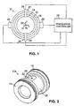
- Fig. 1 is a schematic diagram showing a partial cross-sectional view of an electromagnetic flowmeter.
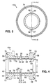
- Figs. 2 and 3 are perspective and front views, respectively, of a metal flow tube and liner in the flowmeter of Fig. 1.
- Fig. 4 is a cross-sectional view of the metal tube
and liner, taken along
line 4--4 of Fig. 3. - Fig. 5 is a perspective view of a perforated grid in the liner of Fig. 4.
- Fig. 6 is a perspective view of the grid of Fig. 5 in the process of formation.
- Fig. 7 is a schematic front view of adjoining perforations in a section of the surface of the grid of Fig. 5.
- Fig. 8 is a partially cut-away side view of an electrode assembly in the flowmeter of Figs. 1-4.
- Fig. 9 is a sectional view of a metal tube and liner for another electromagnetic flowmeter.
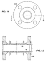
- Figs. 10 through 12 are perspective, front and sectional views, respectively, of another metal tube and liner, the sectional view being taken along line 12-12 of Fig. 11.
- Fig. 13 is a sectional view of another metal tube and liner.
-
- Referring to Fig. 1, an
electromagnetic flowmeter 8 has ametal flow tube 10 for transporting fluid along a longitudinal axis (z axis 12). The metal tube is placed coaxially between aplastic liner 14 and atubular housing 16. - Two
magnetic coil assemblies housing 16 as shown or in between the housing andmetal tube 10. Twoelectrode assemblies apertures processor 28. - In use,
processor 28causes coil assemblies Housing 16 provides a magnetic return path for the magnetic field in the tube.Electrodes processor 28 converts the voltage measurement to a flow measurement.Liner 14 prevents the fluid from corroding the inner surface of the metal tube and thus producing errors in the electrode current measurement. - Referring to Figs. 2 through 4, a wafer
type metal tube 10a with a 38.1 mm (1.5") inner diameter (D) has two oppositeflat sections outer surface 58 for holdingelectrode assemblies 24, 25 (Fig. 1).Apertures - Outer surface 58 (Fig. 3) of
metal tube 10a is covered by an insulator, e.g., 0.05 mm (0.002") of PTFE, to prevent shorting to thehousing 16 when the flowmeter is fully assembled. -
Inner surface 60 ofmetal tube 10a hasbevels faces -
Liner 14 is molded againstinner surface 60 of the metal tube to provide 360 degrees of coverage (Fig. 1). The only gaps in the liner are aligned withapertures Liner 14 also extends out fromapertures 26, 27 (at a thickness t of about 0.762 mm (0.03")), and around faces 66, 68 into dovetails 70, 72. Molding the liner into the holes and dovetails helps fix the liner relative to the metal tube. -
Liner 14 contains ametal grid 76 embedded in a perfluoroalkoxy (PFA)layer 78. The grid ends before bevels 62, 64 on the tube, i.e., at about 6.35 mm (0.25") from the ends of the tube. Eachend -
Apertures apertures metal tube 10a. When the electrodes are inserted intoapertures apertures - Referring to Figs. 5 through 7,
grid 76 includes a perforated cylinder of constant diameter. The cylinder is preferably formed from 304 annealed steel, with a magnetic permeability of less than or equal to 1.05 and a thickness great enough to supportplastic liner 78. For example, steel 0.381 mm (0.015") thick is adequate forliner 14 inmetal tube 10a. -
Holes 148 in the cylinder surface are arranged such thatlines 150 drawn through the centers of the holes form an equilateral triangle, as indicated in Fig. 7. This is accomplished by staggering adjacent rows of holes in the surface of the cylinder.Holes 148 have a diameter of 3.175 mm (0.125") and are spaced 4.775 mm (0.188") apart, center to center. - Stainless steel wires 152 (Fig. 5) are welded to the outer surface of the cylinder along a longitudinal axis of the cylinder. The wires are spaced apart by about one inch along the cylinder's circumference and are each about 0.762 mm (0.03 inch) in diameter. The wires ensure that the grid is properly positioned with respect to the metal tube after assembly, as described in more detail below.
- The cylinder is formed by twisting a strip of perforated
stainless steel 154 into a spiral of constant diameter. Spiral seams 156 on the grids are welded together without leaving any gaps.Wires 152 are then welded onto the outside of the grid. - The plastic liner is mounted on the inside of
metal tube 10a as follows. First,grid 76 is inserted inmetal tube 10a and welded at opposite ends 79, 80 to the tube (Fig. 4).Wires 152 ensure that the inner wall of the tube and the outer surface of the grid have a constant spacing equal to the diameter of the wires. - PFA is next molded onto the inner surface of the tube to form
plastic layer 78. A removable cylindrical mandrel not shown forms the other surface of the mold. The PFA flows through the holes in the grid to fill the space between the grid and the inner wall of the metal tube and to form a layer of constant thickness against the inner surface of the grid. The PFA also flows up out ofapertures - After molding, the
plastic layer 78 andgrid 76 together form aliner 14 with a constant thickness L of 3.05 mm (0.120"). The liner is in contact with the inner wall of the metal tube, whilegrid 76 is spaced 0.635 mm (0.025") from the outer diameter of the liner. - Referring to Fig. 8, each
electrode assembly button type electrode 200 connected to alead assembly 202 at one end. The electrode has ahead 204 at an opposite end with aface 206 for detecting current. An opposite face of the head has threeserrations 210. - The electrode is placed in aperture 26 (27) with its head inside the metal tube. Face 206 is thus exposed to the process fluid when the tube is full, and
serrations 210 protrude into the liner to help fix both the electrode and the liner in place. The portion 14' ofliner 14 molded in the aperture separateselectrode 200 frommetal tube 10. - An insulating
washer 212 is placed on flat section 50 (52) around theportion 14" of liner that extends out of aperture 26 (27). Aceramic washer 214 is placed on top of the insulating washer and aroundportion 14" of the liner. Athird washer 216 is mounted on the insulating washer, and is surrounded by aring 218 holding acircular Belleville spring 220 againstwasher 216. Anut adjustment 222 is placed partially on top of the insulating washer and spring. Theelectrode 200 andnut 222 have mating threads. - The electrode assembly is mounted on the metal tube by first placing electrode 24 (25) in aperture 26 (27) from the inside of the metal tube. The nut adjustment is then used to tighten the
spring 218 andwashers - The portion 14' of liner is usually sufficient to isolate the electrode from the metal tube. For additional insulation, a layer of silicon rubber 224 (e.g., RTV) is placed between
ceramic washer 214 and portion 14' of the liner. - Other embodiments are within the following claims. Referring to Fig. 9, for example,
metal tube 10b is a wafer type tube with a larger inner diameter D and different liner specifications fromtube 10a of Figs. 2 through 4. Diameter D oftube 10b is approximately 76.2 mm (3"), and its grid is 0.762 mm (0.030") thick with a clearance of 0.762 mm (0.030") from the tube. The thickness (L) of theliner 14 inmetal tube 10b is 381 mm (0.150"), and grid is recessed 9.652 mm (0.38") in from the ends of the tube. - Another
metal tube 10c hasflanges Tube 10c has the same liner and grid specifications as the 76.2 mm (3") metal tube of Fig. 9. - Referring to Fig. 13,
tube 10d has an inner diameter of 12.7 mm (0.5"). The specifications oftube 10d differ from the 38.1 mm (1.5") tube described above in that apertures 26, 27 intube 10c provide a clearance of 11.43 mm (0.450") between the grid and electrodes, and the thickness (L) of theliner 14 is 2.286 mm (0.09"). A diameter of each hole in the grid is 1.375 mm (0.062") and a distance between the center of adjoining holes is 2.362 mm (0.093"). - Similarly, a tube 25.4 mm (1") in inner diameter has the same liner specifications as the 12.7 mm (0.5") tube, except the electrode clearance from the grid is 12.7 mm (0.500"). Tubes 101.6 mm (4") and 152.4 mm (6") in inner diameter are similar to the 76.2 mm (3") tube of Fig. 3, except for having a grid thickness of 1.27 mm (0.05") and a liner thickness of 4.318 mm (0.170").
Grid 76 in the 152.4 mm (6") tube is recessed 17.27 mm (0.68") from the ends of the tube. - Each metal tube described above is fitted with
electrode assembly
Claims (6)
- An electromagnetic flowmeter comprising
a tube (10a, b, c, d) for carrying fluid,
a liner (14) disposed on an inner surface (60) of the tube (10a, b, c, d), the liner comprising
a layer (78) of material, and
a perforated cylindrical metal grid (76) embedded in the layer (78),
characterized in that
the grid (76) having holes (148) in its surface, wherein lines (150) connecting a center of each of three adjoining holes (148) form an equilateral triangle, and the flowmeter further comprises
wires (152) welded on an outside surface of the grid (76) and along a longitudinal axis of the grid (76), the wires (152) providing a constant spacing between the grid (76) and the inner surface (60) of the tube (10a, b, c, d). - The flowmeter of claim 1, further characterized in that the wires are parallel to each other.
- The electromagnetic flowmeter of claim 1, wherein the grid (76) has a spiral seam (156).
- The electromagnetic flowmeter of claim 1, wherein the grid (76) is welded to the tube (10a, b, c, d) at a point.
- The flowmeter of claims 1, wherein a diameter of each hole (148) is approximately 3,175 mm and a distance between centers of the holes (148) is approximately 4,775 mm.
- The flowmeter of claims 1, wherein a diameter of each hole (148) is approximately 1,588 mm and a distance between centers of the holes (148) is approximately 2,362 mm.
Priority Applications (1)
| Application Number | Priority Date | Filing Date | Title |
|---|---|---|---|
| EP04024848A EP1519160A3 (en) | 1995-09-29 | 1996-09-27 | Flow tube liner |
Applications Claiming Priority (2)
| Application Number | Priority Date | Filing Date | Title |
|---|---|---|---|
| US08/535,986 US5773723A (en) | 1995-09-29 | 1995-09-29 | Flow tube liner |
| US535986 | 1995-09-29 |
Related Child Applications (1)
| Application Number | Title | Priority Date | Filing Date |
|---|---|---|---|
| EP04024848A Division EP1519160A3 (en) | 1995-09-29 | 1996-09-27 | Flow tube liner |
Publications (2)
| Publication Number | Publication Date |
|---|---|
| EP0766069A1 EP0766069A1 (en) | 1997-04-02 |
| EP0766069B1 true EP0766069B1 (en) | 2005-07-27 |
Family
ID=24136635
Family Applications (2)
| Application Number | Title | Priority Date | Filing Date |
|---|---|---|---|
| EP04024848A Withdrawn EP1519160A3 (en) | 1995-09-29 | 1996-09-27 | Flow tube liner |
| EP96115559A Expired - Lifetime EP0766069B1 (en) | 1995-09-29 | 1996-09-27 | Flow tube liner |
Family Applications Before (1)
| Application Number | Title | Priority Date | Filing Date |
|---|---|---|---|
| EP04024848A Withdrawn EP1519160A3 (en) | 1995-09-29 | 1996-09-27 | Flow tube liner |
Country Status (3)
| Country | Link |
|---|---|
| US (1) | US5773723A (en) |
| EP (2) | EP1519160A3 (en) |
| DE (1) | DE69634969T2 (en) |
Cited By (5)
| Publication number | Priority date | Publication date | Assignee | Title |
|---|---|---|---|---|
| DE202007018760U1 (en) | 2007-10-09 | 2009-04-23 | Krope, Franz | Liner for flow-through valves and flowmeter fittings |
| DE102008054432A1 (en) | 2008-12-09 | 2010-06-10 | Endress + Hauser Flowtec Ag | Measuring device with a measuring tube and method for monitoring the measuring device and device for monitoring a pipeline |
| DE102020129772A1 (en) | 2020-11-11 | 2022-05-12 | Endress+Hauser Flowtec Ag | Electromagnetic flow meter |
| DE102020133612A1 (en) | 2020-12-15 | 2022-06-15 | Endress + Hauser Flowtec Ag | Measuring device and method for determining abrasion |
| DE102020133859A1 (en) | 2020-12-16 | 2022-06-23 | Endress + Hauser Flowtec Ag | Electromagnetic flow meter |
Families Citing this family (55)
| Publication number | Priority date | Publication date | Assignee | Title |
|---|---|---|---|---|
| US6178826B1 (en) | 1998-07-27 | 2001-01-30 | Flowtec Ag | Electrode assembly for electromagnetic flow sensors |
| DK1217338T3 (en) * | 1998-07-27 | 2008-08-04 | Flowtec Ag | Method for assembling an electrode device for magnetic inductive flow sensors |
| US6571642B1 (en) * | 2000-11-02 | 2003-06-03 | Murray F. Feller | Magnetic flow sensor with annular sensing path |
| DE10129388B4 (en) * | 2001-06-20 | 2008-01-10 | Infineon Technologies Ag | Method for producing an electronic component |
| US6722207B1 (en) * | 2002-03-19 | 2004-04-20 | Murray F. Feller | Electro-magnetic flow transducer with insulating scroll |
| US6854342B2 (en) * | 2002-08-26 | 2005-02-15 | Gilbarco, Inc. | Increased sensitivity for turbine flow meter |
| US7111520B2 (en) * | 2002-08-26 | 2006-09-26 | Gilbarco Inc. | Increased sensitivity for liquid meter |
| DE10240024B4 (en) * | 2002-08-27 | 2004-12-16 | Krohne Ag | Magnetic-inductive flow meter |
| JP2004233203A (en) * | 2003-01-30 | 2004-08-19 | Yamatake Corp | Measuring tube for electromagnetic flow meter |
| GB2402219B (en) * | 2003-05-29 | 2006-09-27 | Abb Ltd | Electromagnetic flow meter |
| ATE526561T1 (en) * | 2003-12-11 | 2011-10-15 | Flowtec Ag | MAGNETIC-INDUCTIONAL FLOW SENSOR AND METHOD FOR THE PRODUCTION THEREOF |
| DE10358268A1 (en) * | 2003-12-11 | 2005-07-21 | Endress + Hauser Process Solutions Ag | Magnetoinductive mass flow sensor has a mounting pipe with an insulating liner within it, whereby lining and mounting are linked by a groove in the mounting and a matching projection from the lining |
| GB0329450D0 (en) * | 2003-12-19 | 2004-01-28 | Abb Ltd | Electromagnetic flow meter insert |
| US7497130B2 (en) * | 2004-07-15 | 2009-03-03 | Pdc Facilities, Inc. | Liner for a flow meter |
| US7673523B2 (en) | 2004-11-10 | 2010-03-09 | Siemens Aktiengesellschaft | Tubular insert for a magnetic inductive flow meter |
| EP1859233A1 (en) * | 2005-03-14 | 2007-11-28 | Siemens Aktiengesellschaft | Tubular insert for a magnetically inductive flowmeter |
| US7819139B2 (en) * | 2005-07-14 | 2010-10-26 | Pdc Facilities, Inc. | Liner for a flow meter |
| JP4893920B2 (en) * | 2005-07-15 | 2012-03-07 | 横河電機株式会社 | Electromagnetic flow meter |
| WO2007062226A1 (en) * | 2005-11-28 | 2007-05-31 | Pdc Facilities, Inc. | Filling machine |
| DE102006008451B4 (en) * | 2006-02-23 | 2008-05-21 | Abb Ag | Magnetic-inductive flowmeter with a measuring tube made of metal |
| DE102006018415B4 (en) * | 2006-04-20 | 2008-01-10 | Siemens Ag | Measuring tube for a magnetic inductive flowmeter |
| JP4913490B2 (en) * | 2006-07-18 | 2012-04-11 | 株式会社山武 | Capacity type electromagnetic flow meter |
| GB2440963B (en) * | 2006-08-18 | 2011-06-08 | Abb Ltd | Flow meter |
| GB2440964B (en) * | 2006-08-18 | 2011-08-10 | Abb Ltd | Flow meter |
| DE102006042062A1 (en) | 2006-09-05 | 2008-03-13 | Endress + Hauser Flowtec Ag | The invention relates to a device for measuring the volume or mass flow of a medium in a pipeline |
| DE102006054635A1 (en) * | 2006-11-17 | 2008-05-21 | Endress + Hauser Flowtec Ag | Device for measuring the volume or mass flow of a medium in a pipeline |
| DE102006060445A1 (en) * | 2006-12-19 | 2008-06-26 | Endress + Hauser Flowtec Ag | Device for measuring the volume or mass flow of a medium in a pipeline |
| CH700175B1 (en) * | 2007-07-19 | 2010-07-15 | Aquametro Ag | Flow measuring device. |
| DE102007058898A1 (en) * | 2007-12-05 | 2009-06-10 | Endress + Hauser Flowtec Ag | Electrode for a magnetic-inductive flowmeter |
| DE102008054961A1 (en) * | 2008-12-19 | 2010-07-01 | Endress + Hauser Flowtec Ag | Flow meter and method of making a meter tube of a flow meter |
| JP5202368B2 (en) * | 2009-02-03 | 2013-06-05 | 株式会社東芝 | measuring device |
| WO2010094293A1 (en) * | 2009-02-17 | 2010-08-26 | Siemens Aktiengesellschaft | Electromagnetic flowmeter and method of manufacture thereof |
| DE102009018056B4 (en) * | 2009-04-21 | 2011-01-20 | Qundis Gmbh | Water / heat meter with a transmitter housing and method for producing a transmitter housing |
| JP2010271077A (en) * | 2009-05-19 | 2010-12-02 | Toshiba Corp | Electromagnetic flow meter |
| EP2383548A1 (en) * | 2010-04-29 | 2011-11-02 | Zylum Beteiligungsgesellschaft mbH & Co. Patente II KG | Measuring device and method for measuring the flow speed of a medium flowing through a measuring tube |
| US8806956B2 (en) * | 2012-05-16 | 2014-08-19 | Rosemount Inc. | Fastening system for magnetic flowmeter liner |
| DE102012221616B4 (en) * | 2012-11-27 | 2015-03-12 | Siemens Aktiengesellschaft | Electromagnetic flowmeter |
| DE102013014223B4 (en) * | 2013-08-28 | 2017-03-30 | Sensus Spectrum Llc | Electromagnetic flowmeter for determining the flow of a fluid passing through a measuring tube |
| JP2015105929A (en) * | 2013-12-02 | 2015-06-08 | 株式会社東芝 | Electromagnetic flow meter |
| DE102013114428A1 (en) * | 2013-12-19 | 2015-06-25 | Endress + Hauser Flowtec Ag | Measuring tube for a magnetic-inductive flowmeter and electromagnetic flowmeter |
| DE102013114429A1 (en) * | 2013-12-19 | 2015-06-25 | Endress + Hauser Flowtec Ag | Measuring tube for a magnetic-inductive flowmeter and electromagnetic flowmeter |
| DE102014001479B4 (en) * | 2014-02-06 | 2016-03-10 | Krohne Ag | Gastric table inductive flowmeter |
| US9316514B2 (en) * | 2014-03-26 | 2016-04-19 | Rosemount Inc. | High pressure wafer style magnetic flowmeter |
| US9464926B2 (en) * | 2014-09-23 | 2016-10-11 | Micro Motion, Inc. | Magnetic flowmeter flowtube assembly with spring-energized seal rings |
| DE102014114941A1 (en) * | 2014-10-15 | 2016-04-21 | Endress + Hauser Gmbh + Co. Kg | Hybrid flange |
| DE102015107119A1 (en) | 2015-05-07 | 2016-11-10 | Endress + Hauser Flowtec Ag | Measuring tube and magnetic inductive flowmeter |
| DE102015112018B3 (en) * | 2015-07-23 | 2016-07-14 | Endress+Hauser Flowtec Ag | Magnetic-inductive flowmeter for measuring the flow rate or volume flow of media in a pipeline and method of making such a flowmeter |
| GB2558473B (en) * | 2015-09-14 | 2021-12-22 | Cameron Tech Ltd | Flow meter system |
| DE102016123123A1 (en) * | 2016-11-30 | 2018-05-30 | Endress+Hauser Flowtec Ag | Magnetic-inductive flowmeter |
| US10416011B2 (en) * | 2017-10-16 | 2019-09-17 | Finetek Co., Ltd. | Electromagnetic flowmeter with adjustable electrode structures |
| CN110715695A (en) * | 2018-07-11 | 2020-01-21 | 浙江大学 | A Superconducting Metal Fluid Flow Meter Based on Tube Wall Matrix Electrodes |
| CN110715696A (en) * | 2018-07-11 | 2020-01-21 | 浙江大学 | Superconductive magnetic fluid flowmeter with built-in grating |
| DE102019128542A1 (en) * | 2019-10-22 | 2021-04-22 | Endress+Hauser Flowtec Ag | Method of manufacturing a measuring tube for a flow meter |
| JP7820500B2 (en) | 2021-08-19 | 2026-02-25 | マイクロ モーション インコーポレイテッド | Electromagnetic flowmeter with flow tube liner. |
| US20250244170A1 (en) * | 2024-01-30 | 2025-07-31 | Nix Sensor Ltd. | Fixture for a spectrophotometer |
Family Cites Families (19)
| Publication number | Priority date | Publication date | Assignee | Title |
|---|---|---|---|---|
| US2783173A (en) * | 1954-07-01 | 1957-02-26 | Resistoflex Corp | Method of making laminated tubing |
| US3153779A (en) * | 1958-10-21 | 1964-10-20 | Fisher & Porter Company | Means for suppressing fluctuations in signal-responsive devices utilizing a self biasadjusting class c deadband amplifier in a rebalancing servosystem |
| GB1153295A (en) * | 1965-09-02 | 1969-05-29 | Mawdsley S Ltd | Improvements in or relating to sealing arrangements for electrodes. |
| US3460578A (en) * | 1967-05-01 | 1969-08-12 | Stewart Warner Corp | Composite flexible shaft casing |
| GB1221963A (en) * | 1968-03-27 | 1971-02-10 | Kent Ltd G | Improvements in or relating to electromagnetic flowmeter heads |
| US3771361A (en) * | 1972-04-20 | 1973-11-13 | Emerson Electric Co | Ultrasonically cleaned electrode and flowmeter using it |
| US3980107A (en) * | 1975-05-08 | 1976-09-14 | Champion International Corporation | Helically wound tubular wall material |
| SE428957B (en) * | 1975-06-02 | 1983-08-01 | Warman Int Ltd | INTERIOR LINED HIGH PRESSURE PUMP HOUSE |
| US4358963A (en) * | 1979-09-12 | 1982-11-16 | Fischer & Porter Company | Unitary electromagnetic flowmeter with sealed coils |
| US4631969A (en) * | 1977-02-23 | 1986-12-30 | Fischer & Porter Company | Capacitance-type electrode assemblies for electromagnetic flowmeter |
| US4297895A (en) * | 1979-08-09 | 1981-11-03 | Emerson Electric Co. | Field replaceable electrode assembly for magnetic flowmeter |
| US4329879A (en) * | 1980-07-14 | 1982-05-18 | Fischer & Porter Co. | Insulating liner for electromagnetic flowmeter tube |
| US4388834A (en) * | 1981-03-31 | 1983-06-21 | Fischer & Porter Company | Electromagnetic flowmeter having a monolithic conduit |
| JPS59137822A (en) * | 1983-01-28 | 1984-08-08 | Yamatake Honeywell Co Ltd | Manufacture of detecting pipe for electromagnetic flowmeter |
| US4565619A (en) * | 1983-02-18 | 1986-01-21 | The Foxboro Company | Composite electrode structure |
| JPH0229169B2 (en) * | 1983-04-27 | 1990-06-28 | Yamatake Honeywell Co Ltd | DENJIRYURYOKEI |
| US4773275A (en) * | 1986-05-27 | 1988-09-27 | The Foxboro Company | Seal for ceramic flow tube |
| JPH0198318A (en) * | 1987-10-09 | 1989-04-17 | Nec Corp | Input buffer circuit |
| DE3917975A1 (en) * | 1989-06-02 | 1990-12-13 | Danfoss As | METHOD FOR PRODUCING A MEASURING TUBE FOR AN ELECTROMAGNETIC FLOW METER AND MEASURING TUBE |
-
1995
- 1995-09-29 US US08/535,986 patent/US5773723A/en not_active Expired - Lifetime
-
1996
- 1996-09-27 EP EP04024848A patent/EP1519160A3/en not_active Withdrawn
- 1996-09-27 EP EP96115559A patent/EP0766069B1/en not_active Expired - Lifetime
- 1996-09-27 DE DE69634969T patent/DE69634969T2/en not_active Expired - Lifetime
Cited By (8)
| Publication number | Priority date | Publication date | Assignee | Title |
|---|---|---|---|---|
| DE202007018760U1 (en) | 2007-10-09 | 2009-04-23 | Krope, Franz | Liner for flow-through valves and flowmeter fittings |
| DE102008054432A1 (en) | 2008-12-09 | 2010-06-10 | Endress + Hauser Flowtec Ag | Measuring device with a measuring tube and method for monitoring the measuring device and device for monitoring a pipeline |
| DE102020129772A1 (en) | 2020-11-11 | 2022-05-12 | Endress+Hauser Flowtec Ag | Electromagnetic flow meter |
| WO2022100917A1 (en) | 2020-11-11 | 2022-05-19 | Endress+Hauser Flowtec Ag | Magnetic-inductive flow meter |
| DE102020133612A1 (en) | 2020-12-15 | 2022-06-15 | Endress + Hauser Flowtec Ag | Measuring device and method for determining abrasion |
| WO2022128414A1 (en) | 2020-12-15 | 2022-06-23 | Endress+Hauser Flowtec Ag | Measuring device and method for determining an abrasion |
| DE102020133859A1 (en) | 2020-12-16 | 2022-06-23 | Endress + Hauser Flowtec Ag | Electromagnetic flow meter |
| WO2022128419A1 (en) | 2020-12-16 | 2022-06-23 | Endress+Hauser Flowtec Ag | Magnetic-inductive flow meter |
Also Published As
| Publication number | Publication date |
|---|---|
| US5773723A (en) | 1998-06-30 |
| DE69634969T2 (en) | 2006-06-01 |
| EP1519160A3 (en) | 2010-02-10 |
| EP0766069A1 (en) | 1997-04-02 |
| DE69634969D1 (en) | 2005-09-01 |
| EP1519160A2 (en) | 2005-03-30 |
Similar Documents
| Publication | Publication Date | Title |
|---|---|---|
| US5773723A (en) | Flow tube liner | |
| US5280727A (en) | Electromagnetic flow measuring tube and method of making same | |
| JP2004233203A (en) | Measuring tube for electromagnetic flow meter | |
| JP2793177B2 (en) | Manufacturing method of measuring tube of electromagnetic flow sensor | |
| CN105849522A (en) | Pipe fittings that allow non-destructive pressure testing of seal integrity | |
| GB2160982A (en) | Electromagnetic flow meter | |
| US3180144A (en) | Flowmeter electrodes | |
| US7178407B2 (en) | Magnetic-inductive flow sensor and method for its manufacture | |
| JPH05240383A (en) | Coupling with electric insulating flange for pipeline and the like | |
| JPH10197301A (en) | Measuring tube for electromagnetic flow meter | |
| US5307687A (en) | Electromagnetic flowmeter | |
| US7126343B1 (en) | Conductivity probe with toroid keeper | |
| US4626786A (en) | Liquid conductivity probe | |
| KR20170124178A (en) | Pipe connection structure air conditioning system | |
| US10620024B2 (en) | Magneto-inductive flow measuring device having a support tube with structure to prevent rotary movement of the liner | |
| JP2002039821A (en) | Lining tube | |
| CN100472218C (en) | Method and apparatus for measuring electrical conductivity | |
| JP3139057B2 (en) | Electromagnetic flow meter | |
| JP3340355B2 (en) | Measuring tube for electromagnetic flow meter | |
| JP3497572B2 (en) | Electromagnetic flow meter detector | |
| JPH11153274A (en) | Pipe fittings | |
| JP2545656B2 (en) | Manufacturing method of electrode for electromagnetic flow meter | |
| JPH07239068A (en) | Water leakage detection type flexible pipe joint | |
| JPS59137822A (en) | Manufacture of detecting pipe for electromagnetic flowmeter | |
| US5394831A (en) | Resistance milk flow sensor |
Legal Events
| Date | Code | Title | Description |
|---|---|---|---|
| PUAI | Public reference made under article 153(3) epc to a published international application that has entered the european phase |
Free format text: ORIGINAL CODE: 0009012 |
|
| AK | Designated contracting states |
Kind code of ref document: A1 Designated state(s): CH DE FR GB LI |
|
| 17P | Request for examination filed |
Effective date: 19970814 |
|
| 17Q | First examination report despatched |
Effective date: 20020729 |
|
| 111Z | Information provided on other rights and legal means of execution |
Free format text: CHDEFRGBLI Effective date: 20040607 |
|
| GRAP | Despatch of communication of intention to grant a patent |
Free format text: ORIGINAL CODE: EPIDOSNIGR1 |
|
| GRAS | Grant fee paid |
Free format text: ORIGINAL CODE: EPIDOSNIGR3 |
|
| RAP1 | Party data changed (applicant data changed or rights of an application transferred) |
Owner name: SHERIDAN, MICHAEL R. Owner name: INVENSYS SYSTEMS, INC. |
|
| GRAA | (expected) grant |
Free format text: ORIGINAL CODE: 0009210 |
|
| AK | Designated contracting states |
Kind code of ref document: B1 Designated state(s): CH DE FR GB LI |
|
| REG | Reference to a national code |
Ref country code: GB Ref legal event code: FG4D |
|
| REG | Reference to a national code |
Ref country code: CH Ref legal event code: EP |
|
| REF | Corresponds to: |
Ref document number: 69634969 Country of ref document: DE Date of ref document: 20050901 Kind code of ref document: P |
|
| ET | Fr: translation filed | ||
| PLBE | No opposition filed within time limit |
Free format text: ORIGINAL CODE: 0009261 |
|
| STAA | Information on the status of an ep patent application or granted ep patent |
Free format text: STATUS: NO OPPOSITION FILED WITHIN TIME LIMIT |
|
| 26N | No opposition filed |
Effective date: 20060428 |
|
| PGFP | Annual fee paid to national office [announced via postgrant information from national office to epo] |
Ref country code: CH Payment date: 20140915 Year of fee payment: 19 |
|
| PGFP | Annual fee paid to national office [announced via postgrant information from national office to epo] |
Ref country code: GB Payment date: 20140924 Year of fee payment: 19 |
|
| PGFP | Annual fee paid to national office [announced via postgrant information from national office to epo] |
Ref country code: FR Payment date: 20140906 Year of fee payment: 19 |
|
| PGFP | Annual fee paid to national office [announced via postgrant information from national office to epo] |
Ref country code: DE Payment date: 20150922 Year of fee payment: 20 |
|
| REG | Reference to a national code |
Ref country code: CH Ref legal event code: PL |
|
| GBPC | Gb: european patent ceased through non-payment of renewal fee |
Effective date: 20150927 |
|
| REG | Reference to a national code |
Ref country code: FR Ref legal event code: ST Effective date: 20160531 |
|
| PG25 | Lapsed in a contracting state [announced via postgrant information from national office to epo] |
Ref country code: CH Free format text: LAPSE BECAUSE OF NON-PAYMENT OF DUE FEES Effective date: 20150930 Ref country code: GB Free format text: LAPSE BECAUSE OF NON-PAYMENT OF DUE FEES Effective date: 20150927 Ref country code: LI Free format text: LAPSE BECAUSE OF NON-PAYMENT OF DUE FEES Effective date: 20150930 |
|
| PG25 | Lapsed in a contracting state [announced via postgrant information from national office to epo] |
Ref country code: FR Free format text: LAPSE BECAUSE OF NON-PAYMENT OF DUE FEES Effective date: 20150930 |
|
| REG | Reference to a national code |
Ref country code: DE Ref legal event code: R071 Ref document number: 69634969 Country of ref document: DE |