EP0766007B1 - High-pressure multistage pump - Google Patents
High-pressure multistage pump Download PDFInfo
- Publication number
- EP0766007B1 EP0766007B1 EP96115494A EP96115494A EP0766007B1 EP 0766007 B1 EP0766007 B1 EP 0766007B1 EP 96115494 A EP96115494 A EP 96115494A EP 96115494 A EP96115494 A EP 96115494A EP 0766007 B1 EP0766007 B1 EP 0766007B1
- Authority
- EP
- European Patent Office
- Prior art keywords
- pressure
- cover
- outer casing
- impellers
- inner casing
- Prior art date
- Legal status (The legal status is an assumption and is not a legal conclusion. Google has not performed a legal analysis and makes no representation as to the accuracy of the status listed.)
- Expired - Lifetime
Links
- 239000007788 liquid Substances 0.000 claims description 8
- 238000004891 communication Methods 0.000 claims description 6
- 230000000295 complement effect Effects 0.000 description 4
- 239000012530 fluid Substances 0.000 description 4
- 238000005086 pumping Methods 0.000 description 2
- 239000000463 material Substances 0.000 description 1
- 238000012986 modification Methods 0.000 description 1
- 230000004048 modification Effects 0.000 description 1
- 238000007789 sealing Methods 0.000 description 1
- XLYOFNOQVPJJNP-UHFFFAOYSA-N water Substances O XLYOFNOQVPJJNP-UHFFFAOYSA-N 0.000 description 1
Images


Classifications
-
- F—MECHANICAL ENGINEERING; LIGHTING; HEATING; WEAPONS; BLASTING
- F04—POSITIVE - DISPLACEMENT MACHINES FOR LIQUIDS; PUMPS FOR LIQUIDS OR ELASTIC FLUIDS
- F04D—NON-POSITIVE-DISPLACEMENT PUMPS
- F04D29/00—Details, component parts, or accessories
- F04D29/08—Sealings
- F04D29/086—Sealings especially adapted for liquid pumps
-
- F—MECHANICAL ENGINEERING; LIGHTING; HEATING; WEAPONS; BLASTING
- F04—POSITIVE - DISPLACEMENT MACHINES FOR LIQUIDS; PUMPS FOR LIQUIDS OR ELASTIC FLUIDS
- F04D—NON-POSITIVE-DISPLACEMENT PUMPS
- F04D1/00—Radial-flow pumps, e.g. centrifugal pumps; Helico-centrifugal pumps
- F04D1/06—Multi-stage pumps
Definitions
- the present invention relates to a high-pressure multistage pump having an inner casing which comprises upper and lower casing members, a barrel-shaped outer casing which houses the inner casing, and a cover which sealingly closes an axial open end of the outer casing.
- High-pressure multistage pumps have heretofore been used as boiler feed pumps for supplying water to boilers under a discharge pressure ranging from 300 to 500 kg/cm 2 . It is expected that the high-pressure multistage pumps will be used in applications for higher discharge pressures.
- FIG. 7 of the accompanying drawings shows a conventional high-pressure four-stage pump.
- a conventional high-pressure four-stage pump has a barrel-shaped outer casing 1 and an inner casing 2A housed in the barrel-shaped outer casing 1.
- the inner casing 2A comprises upper and lower casing members.
- the outer casing 1 has an axial open end covered with a cover 3C.
- the inner casing 2A accommodates an axial array of impellers 21a - 21d mounted on a rotatable pump shaft 20 which axially extends through the inner casing 2A and the cover 3C.
- the pump shaft 20 has an end rotatably supported by a radial bearing 24 on a bracket 22 which is attached to an end of the inner casing 2A remote from the cover 3C.
- a mechanical seal 25 is interposed between the inner casing 2A and the pump shaft 20.
- the other end of the pump shaft 20 is rotatably supported by a radial bearing 24 on a bracket 23 attached to the cover 3C.
- a thrust bearing 26 is provided on the bracket 23 to receive thrust forces applied to the pump shaft 20.
- a mechanical seal 25 is interposed between the cover 3C and the pump shaft 20.
- the impellers 21a, 21b provide first and second stages a, b, respectively, which define a low-pressure region A in the inner casing 2A, and the impellers 21c, 21d provide third and fourth stages c, d, respectively, which define a high-pressure region B in the inner casing 2A.
- the impellers 21a, 21b in the low-pressure region A and the impellers 21c, 21d in the high-pressure region B are positioned in back-to-back relation in the inner casing 2A.
- the impellers 21a, 21b have respective suction mouths, which are open axially outwardly, and the impellers 21c, 21d have respective suction mouths which are open axially outwardly.
- a liquid which is introduced into the inner casing 2A through an inlet chamber 17 defined in the inner casing 2 is pressurized successively through the first through fourth stages a - d by the impellers 21a - 21d, and then discharged under a high discharge pressure from the inner casing 2A through an outlet port 17A.
- an inner space 10 which is defined by the outer casing 1, the inner casing 2A and the cover 3C communicates with the outlet port 17A, and is filled with the liquid having the high discharge pressure.
- the cover 3C needs to be thick enough to withstand the high discharge pressure. It is difficult to effectively seal the high discharge pressure in the inner space 10 by a gasket 5 interposed between the outer casing 1 and the cover 3C. Since large forces are required to tighten the gasket 5 in place, cover bolts 6A used to fasten the cover 3C are relatively large in diameter (see Japanese patent publication No. 56-41482, for example).
- Japanese patent publication No. 63-3160 discloses the use of shear keys instead of cover bolts for allowing a high-pressure multistage pump to be assembled and disassembled with ease, and also reveals the use of a cartridge structure for facilitating internal elements.
- the shear keys require a gasket which does not need to be tightened. In applications such as boiler feed pumps which experience frequent thermal or pressure cycles and seal surface deformations, however, the gasket cannot maintain stable sealing performance, and the shear keys often fail to operate as intended.
- US-A-3 861 825 discloses a multistage centrifugal pump comprising: a divided pump housing having a generally round and elongated pumping chamber defined within said housing, said housing including a lower case and an upper case, releasable fastener means for releasably retaining said upper and lower cases in assembled relation, a rotatably mounted pump impeller assembly having a rotatable shaft and a plurality of impellers serially mounted on said shaft and disposed within said chamber, a plurality of ring-shaped interstage pump volute members disposed around said shaft and between said impellers, means for releasably mounting said pump volute members within said chamber and on said upper and lower cases, each of said interstage pump volute members comprising complementary segments, and second releasable fastener means for releasably joining said complementary segments in assembled relation, wherein said means for mounting said pump volute members within said chamber and on said upper and lower cases comprise circumferential radial flanges on said complementary
- US-A-2 678 606 discloses a multi-stage centrifugal pump having a hollow cylindrical outer casing and an inner casing including a plurality of pumping stages having flow passages and impellers.
- fluid is introduced into a suction eye of the first stage impeller from a suction passage formed in the end of the outer casing, and is pressurized progressively by the impellers.
- the fluid discharged from the final stage impeller passes through a discharge outlet and is then discharged from an outlet of the outer casing.
- non-pressurized fluid is supplied to the suction passage.
- FR-A-610 876 discloses a high pressure multistage pump with a low pressure region (impeller 1) and a high pressure region (impellers 2, 3, 4), in which one of the impellers (impeller 2) has a suction chamber developing a lowermost pressure in the high-pressure region. That is, the internal pressure developed in the suction chamber of impeller 2 is about one-fourth of the discharge pressure.
- the multistage pump comprises a barrel-shaped outer casing having an outlet port, an inner casing housed in the barrel-shaped outer casing, a cover sealingly closing an axial end of the outer casing, a pump shaft rotatably supported in the inner casing and the cover, and an array of impellers mounted on the pump shaft, one of the impellers having a suction chamber adjacent to the cover, wherein the outer casing, the inner casing and the cover jointly define an inner space held in communication with the suction chamber.
- the array of the impellers is divided into two groups in a low-pressure region and a high-pressure region, the one of impellers has the suction chamber developing a lowermost pressure in the high-pressure region.
- the high-pressure multistage pump further comprises a lip gasket interposed between the outer casing and the inner casing and providing a seal between the outlet port and the inner space.
- the high-pressure multistage pump further comprises shear keys by which the cover is attached to the outer casing, and a lip gasket interposed between the outer casing and the cover.
- the inner casing has an inlet chamber through which a liquid is introduced into said inner casing, an O-ring is disposed axially outwardly of the lip gasket, and a space is defined between the lip gasket and the O-ring and held in communication with the inlet chamber.
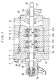
- FIG. 1 shows a high-pressure four-stage pump according to a first embodiment of the present invention.
- the high-pressure four-stage pump has a barrel-shaped outer casing 1 and an inner casing 2 housed in the barrel-shaped outer casing 1.
- the inner casing 2 comprises upper and lower casing members.
- the outer casing 1 has an axial open end covered with a cover 3.
- the inner casing 2 accommodates an axial array of impellers 21a - 21d mounted on a rotatable pump shaft 20 which axially extends through the inner casing 2 and the cover 3.
- the pump shaft 20 has an end rotatably supported by a radial bearing 24 on a bracket 22 which is attached to an end of the inner casing 2 remote from the cover 3.
- a mechanical seal 25 is interposed between the inner casing 2 and the pump shaft 20.
- the other end of the pump shaft 20 is rotatably supported by a radial bearing 24 on a bracket 23 attached to the cover 3.
- a thrust bearing 26 is provided on the bracket 23 to receive thrust forces applied to the pump shaft 20.
- a mechanical seal 25 is interposed between the cover 3 and the pump shaft 20.
- the impellers 21a, 21b provide first and second stages a, b, respectively, which define a low-pressure region A in the inner casing 2, and the impellers 21c, 21d provide third and fourth stages c, d, respectively, which define a high-pressure region B in the inner casing 2.
- the impellers 21a, 21b in the low-pressure region A and the impellers 21c, 21d in the high-pressure region B are positioned in back-to-back relation in the inner casing 2.
- the impellers 21a, 21b have respective suction mouths, which are open axially outwardly, and the impellers 21c, 21d have respective suction mouths which are open axially outwardly.
- a liquid which is introduced into the inner casing 2 through an inlet chamber 17 defined in the inner casing 2 is pressurized successively through the first through fourth stages a - d by the impellers 21a - 21d, and then discharged under a high discharge pressure from the inner casing 2 through an outlet port 17A.
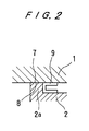
- FIG. 2 is an enlarged fragmentary cross-sectional view of an encircled portion C in FIG. 1.
- the inner casing 2 has a radial flange 2a on an end thereof which faces a cover 3 fastened to the outer casing 1 by cover bolts 6.
- the cover 3 sealingly closes an axial open end of the outer casing 1.
- the radial flange 2a has a radially outer surface 7 held against an inner circumferential surface of the outer casing 1.
- a lip gasket 9 is fitted between the inner circumferential surface of the outer casing 1 and an outer circumferential surface of the inner casing 2, and held against an axial end surface of the radial flange 2a.
- the lip gasket 9 serves to seal the contacting surfaces of the radial flange 2a and the outer casing 1, thereby providing a seal between the outlet port 17A and an inner space 10.
- the inner space 10 is defined by the outer casing 1, the inner casing 2 and the cover 3, and communicates with a suction chamber 11 of the impeller 21c which is positioned most closely to the cover 3.
- a pressure which is developed in the inner space 10 is the same as the suction pressure of the impeller 21c.
- the suction chamber 11 communicates with a discharge chamber 12 of the impeller 21b which is positioned in a portion of the low-pressure region A that is closer to the center of the inner casing 2, through an inner passage (not shown) defined in the inner casing 2. Therefore, the inner space 10 has a pressure which is the same as the discharge pressure in the discharge chamber 12.
- the discharge pressure Pf in the discharge chamber 12 differs depending on whether an extra impeller produced when the odd number of impellers are divided into two groups in the respective low- and high-pressure regions A, B is added to the low-pressure region A or the high-pressure region B. In any case, however, the internal pressure acting on the cover 3 is much smaller than the discharge pressure Pd of the pump.
- the thickness of the cover 3 and the forces required to fasten the cover bolts 6, and hence the number and size of the cover bolts, are smaller than those of the conventional high-pressure multistage pump in which the discharge pressure directly acts on the cover 3C (see FIG. 7). Furthermore, the pressure applied to the gasket 5 between the outer casing 1 and the cover 3 is lower, thus increasing the reliability of the gasket 5.
- FIG. 3 shows a high-pressure multistage pump according to a second embodiment of the present invention.
- the high-pressure multistage pump according to the second embodiment is essentially the same as the high-pressure multistage pump according to the first embodiment except that shear keys 13, rather than the cover bolts 6, are used to fasten a cover 3A to an outer casing 1A.
- the cover 3A is fitted in the outer casing 1A, and the shear keys 13, each in the form of a segment of an annular shape, are then fitted in the outer casing 1A to hold the cover 3A in place.
- FIG. 4 is an enlarged fragmentary cross-sectional view of an encircled portion D in FIG. 3. Since the shear keys 13 do not produce gasket tightening forces, as shown in FIG. 4, a lip gasket 14 which does not need to be tightened is positioned to provide a seal between the outer casing 1A and the cover 3A.
- the internal pressure acting on the cover 3A is about half the discharge pressure of the pump.
- any shear keys used therein are required to be considerably large in size and hence are not practical, in view of safety margins required for the design strength and fatigue life.
- the shear keys 13 which support the cover 3A against the internal pressure may be reduced in size, and can be incorporated in high-pressure boiler feed pumps.
- FIG. 5 shows a high-pressure multistage pump according to a third embodiment of the present invention.
- FIG. 6 is an enlarged fragmentary cross-sectional view of an encircled portion E in FIG. 5.
- an O-ring 15 and a backup ring 16 are disposed in a cover 3B axially outwardly of the lip gasket 14.
- An annular groove 19 is defined in the cover 3B axially between the lip gasket 14 and the O-ring 15 and held in communication with the inlet chamber 17 through a passage 18a defined in the cover 3B and a pipe 18 mounted on the outer casing 1A.
- the suction pressure is applied to the O-ring 15, thus making it easy for the O-ring 15 to provide an effective seal between the outer casing 1A and the cover 3B.
- the structure according to the third embodiment is effective to increase the safety of the high-pressure multistage pump against leaks through the lip gasket 14.
- lip gaskets are shown as being incorporated in high-pressure multistage pumps according to the illustrated embodiments, other seal members such as V-shaped gaskets may be used in normal-temperature applications such as a descaling pump or the like.
- the thickness of the cover can be small and the size of the cover bolts can be small.
- application range in the high-pressure multistage pumps can be expanded by the use of the shear keys.
Landscapes
- Engineering & Computer Science (AREA)
- Mechanical Engineering (AREA)
- General Engineering & Computer Science (AREA)
- Structures Of Non-Positive Displacement Pumps (AREA)
Description
- The present invention relates to a high-pressure multistage pump having an inner casing which comprises upper and lower casing members, a barrel-shaped outer casing which houses the inner casing, and a cover which sealingly closes an axial open end of the outer casing.
- High-pressure multistage pumps have heretofore been used as boiler feed pumps for supplying water to boilers under a discharge pressure ranging from 300 to 500 kg/cm2. It is expected that the high-pressure multistage pumps will be used in applications for higher discharge pressures.
- FIG. 7 of the accompanying drawings shows a conventional high-pressure four-stage pump. As shown in FIG. 7, a conventional high-pressure four-stage pump has a barrel-shaped
outer casing 1 and aninner casing 2A housed in the barrel-shapedouter casing 1. Theinner casing 2A comprises upper and lower casing members. Theouter casing 1 has an axial open end covered with acover 3C. - The
inner casing 2A accommodates an axial array ofimpellers 21a - 21d mounted on arotatable pump shaft 20 which axially extends through theinner casing 2A and thecover 3C. Thepump shaft 20 has an end rotatably supported by aradial bearing 24 on abracket 22 which is attached to an end of theinner casing 2A remote from thecover 3C. Amechanical seal 25 is interposed between theinner casing 2A and thepump shaft 20. - The other end of the
pump shaft 20 is rotatably supported by aradial bearing 24 on abracket 23 attached to thecover 3C. A thrust bearing 26 is provided on thebracket 23 to receive thrust forces applied to thepump shaft 20. Amechanical seal 25 is interposed between thecover 3C and thepump shaft 20. - The
impellers inner casing 2A, and theimpellers inner casing 2A. Theimpellers impellers inner casing 2A. Theimpellers impellers inner casing 2A through aninlet chamber 17 defined in theinner casing 2 is pressurized successively through the first through fourth stages a - d by theimpellers 21a - 21d, and then discharged under a high discharge pressure from theinner casing 2A through anoutlet port 17A. - In the conventional high-pressure four-stage pump shown in FIG. 7, an
inner space 10 which is defined by theouter casing 1, theinner casing 2A and thecover 3C communicates with theoutlet port 17A, and is filled with the liquid having the high discharge pressure. In order to confine the liquid having the high discharge pressure within theinner space 10, thecover 3C needs to be thick enough to withstand the high discharge pressure. It is difficult to effectively seal the high discharge pressure in theinner space 10 by agasket 5 interposed between theouter casing 1 and thecover 3C. Since large forces are required to tighten thegasket 5 in place,cover bolts 6A used to fasten thecover 3C are relatively large in diameter (see Japanese patent publication No. 56-41482, for example). - Japanese patent publication No. 63-3160 discloses the use of shear keys instead of cover bolts for allowing a high-pressure multistage pump to be assembled and disassembled with ease, and also reveals the use of a cartridge structure for facilitating internal elements. The shear keys require a gasket which does not need to be tightened. In applications such as boiler feed pumps which experience frequent thermal or pressure cycles and seal surface deformations, however, the gasket cannot maintain stable sealing performance, and the shear keys often fail to operate as intended.
- US-A-3 861 825 discloses a multistage centrifugal pump comprising: a divided pump housing having a generally round and elongated pumping chamber defined within said housing, said housing including a lower case and an upper case, releasable fastener means for releasably retaining said upper and lower cases in assembled relation, a rotatably mounted pump impeller assembly having a rotatable shaft and a plurality of impellers serially mounted on said shaft and disposed within said chamber, a plurality of ring-shaped interstage pump volute members disposed around said shaft and between said impellers, means for releasably mounting said pump volute members within said chamber and on said upper and lower cases, each of said interstage pump volute members comprising complementary segments, and second releasable fastener means for releasably joining said complementary segments in assembled relation, wherein said means for mounting said pump volute members within said chamber and on said upper and lower cases comprise circumferential radial flanges on said complementary segments and cooperating groove means in said upper and lower cases for receiving said flanges, and detent means on each of said volute members and complementary detent means on at least one of said cases for preventing rotation of said volute members in said cases. In this pump, non-pressurized fluid is supplied to the suction chamber.
- US-A-2 678 606 discloses a multi-stage centrifugal pump having a hollow cylindrical outer casing and an inner casing including a plurality of pumping stages having flow passages and impellers. In this pump, fluid is introduced into a suction eye of the first stage impeller from a suction passage formed in the end of the outer casing, and is pressurized progressively by the impellers. The fluid discharged from the final stage impeller passes through a discharge outlet and is then discharged from an outlet of the outer casing. Here also, non-pressurized fluid is supplied to the suction passage.
- FR-A-610 876 discloses a high pressure multistage pump with a low pressure region (impeller 1) and a high pressure region (
impellers impeller 2 is about one-fourth of the discharge pressure. - It is therefore an object of the present invention to provide a high-pressure multistage pump which develops a reduced internal pressure imposed on a cover attached to an outer casing.
- According to the present invention, there is provided a high-pressure multistage pump as set forth in
claim 1. The multistage pump comprises a barrel-shaped outer casing having an outlet port, an inner casing housed in the barrel-shaped outer casing, a cover sealingly closing an axial end of the outer casing, a pump shaft rotatably supported in the inner casing and the cover, and an array of impellers mounted on the pump shaft, one of the impellers having a suction chamber adjacent to the cover, wherein the outer casing, the inner casing and the cover jointly define an inner space held in communication with the suction chamber. - The array of the impellers is divided into two groups in a low-pressure region and a high-pressure region, the one of impellers has the suction chamber developing a lowermost pressure in the high-pressure region.
- The high-pressure multistage pump further comprises a lip gasket interposed between the outer casing and the inner casing and providing a seal between the outlet port and the inner space.
- The high-pressure multistage pump further comprises shear keys by which the cover is attached to the outer casing, and a lip gasket interposed between the outer casing and the cover. The inner casing has an inlet chamber through which a liquid is introduced into said inner casing, an O-ring is disposed axially outwardly of the lip gasket, and a space is defined between the lip gasket and the O-ring and held in communication with the inlet chamber.
- The above and other objects, features, and advantages of the present invention will become apparent from the following description when taken in conjunction with the accompanying drawings which illustrate preferred embodiments of the present invention by way of example.
-
- FIG. 1 is an axial cross-sectional view of a high-pressure four-stage pump according to a first embodiment of the present invention;
- FIG. 2 is an enlarged fragmentary cross-sectional view of an encircled portion C of the high-pressure four-stage pump shown in FIG. 1;
- FIG. 3 is an axial cross-sectional view of a high-pressure four-stage pump according to a second embodiment of the present invention;
- FIG. 4 is an enlarged fragmentary cross-sectional view of an encircled portion D of the high-pressure four-stage pump shown in FIG. 3;
- FIG. 5 is an axial cross-sectional view of a high-pressure four-stage pump according to a third embodiment of the present invention;
- FIG. 6 is an enlarged fragmentary cross-sectional view of an encircled portion E of the high-pressure four-stage pump shown in FIG. 5; and
- FIG. 7 is an axial cross-sectional view of a conventional high-pressure four-stage pump.
-
- Like or corresponding parts are denoted by like or corresponding reference numerals throughout views.
- FIG. 1 shows a high-pressure four-stage pump according to a first embodiment of the present invention. As shown FIG. 1, the high-pressure four-stage pump has a barrel-shaped
outer casing 1 and aninner casing 2 housed in the barrel-shapedouter casing 1. Theinner casing 2 comprises upper and lower casing members. Theouter casing 1 has an axial open end covered with acover 3. - The
inner casing 2 accommodates an axial array ofimpellers 21a - 21d mounted on arotatable pump shaft 20 which axially extends through theinner casing 2 and thecover 3. Thepump shaft 20 has an end rotatably supported by aradial bearing 24 on abracket 22 which is attached to an end of theinner casing 2 remote from thecover 3. Amechanical seal 25 is interposed between theinner casing 2 and thepump shaft 20. - The other end of the
pump shaft 20 is rotatably supported by aradial bearing 24 on abracket 23 attached to thecover 3. A thrust bearing 26 is provided on thebracket 23 to receive thrust forces applied to thepump shaft 20. Amechanical seal 25 is interposed between thecover 3 and thepump shaft 20. - The
impellers inner casing 2, and theimpellers inner casing 2. Theimpellers impellers inner casing 2. Theimpellers impellers inner casing 2 through aninlet chamber 17 defined in theinner casing 2 is pressurized successively through the first through fourth stages a - d by theimpellers 21a - 21d, and then discharged under a high discharge pressure from theinner casing 2 through anoutlet port 17A. - FIG. 2 is an enlarged fragmentary cross-sectional view of an encircled portion C in FIG. 1.
- As shown in FIG. 2, the
inner casing 2 has aradial flange 2a on an end thereof which faces acover 3 fastened to theouter casing 1 bycover bolts 6. Thecover 3 sealingly closes an axial open end of theouter casing 1. Theradial flange 2a has a radiallyouter surface 7 held against an inner circumferential surface of theouter casing 1. Alip gasket 9 is fitted between the inner circumferential surface of theouter casing 1 and an outer circumferential surface of theinner casing 2, and held against an axial end surface of theradial flange 2a. Thelip gasket 9 serves to seal the contacting surfaces of theradial flange 2a and theouter casing 1, thereby providing a seal between theoutlet port 17A and aninner space 10. - The
inner space 10 is defined by theouter casing 1, theinner casing 2 and thecover 3, and communicates with asuction chamber 11 of theimpeller 21c which is positioned most closely to thecover 3. A pressure which is developed in theinner space 10 is the same as the suction pressure of theimpeller 21c. As well known in the art, thesuction chamber 11 communicates with adischarge chamber 12 of theimpeller 21b which is positioned in a portion of the low-pressure region A that is closer to the center of theinner casing 2, through an inner passage (not shown) defined in theinner casing 2. Therefore, theinner space 10 has a pressure which is the same as the discharge pressure in thedischarge chamber 12. - The discharge pressure Pf in the
discharge chamber 12 is expressed as follows:cover 3 is about half the discharge pressure Pd of the pump. - If the high-pressure four-stage pump has an odd number of impellers, rather than an even number of impellers as shown in FIG. 1, then the discharge pressure Pf in the
discharge chamber 12 differs depending on whether an extra impeller produced when the odd number of impellers are divided into two groups in the respective low- and high-pressure regions A, B is added to the low-pressure region A or the high-pressure region B. In any case, however, the internal pressure acting on thecover 3 is much smaller than the discharge pressure Pd of the pump. - Therefore, the thickness of the
cover 3 and the forces required to fasten thecover bolts 6, and hence the number and size of the cover bolts, are smaller than those of the conventional high-pressure multistage pump in which the discharge pressure directly acts on thecover 3C (see FIG. 7). Furthermore, the pressure applied to thegasket 5 between theouter casing 1 and thecover 3 is lower, thus increasing the reliability of thegasket 5. - FIG. 3 shows a high-pressure multistage pump according to a second embodiment of the present invention. The high-pressure multistage pump according to the second embodiment is essentially the same as the high-pressure multistage pump according to the first embodiment except that
shear keys 13, rather than thecover bolts 6, are used to fasten acover 3A to anouter casing 1A. Specifically, thecover 3A is fitted in theouter casing 1A, and theshear keys 13, each in the form of a segment of an annular shape, are then fitted in theouter casing 1A to hold thecover 3A in place. - FIG. 4 is an enlarged fragmentary cross-sectional view of an encircled portion D in FIG. 3. Since the
shear keys 13 do not produce gasket tightening forces, as shown in FIG. 4, alip gasket 14 which does not need to be tightened is positioned to provide a seal between theouter casing 1A and thecover 3A. - The internal pressure acting on the
cover 3A is about half the discharge pressure of the pump. In high-pressure boiler feed pumps which are started and stopped once a day and hence experience frequent thermal and pressure variations, any shear keys used therein are required to be considerably large in size and hence are not practical, in view of safety margins required for the design strength and fatigue life. According to the second embodiment, since the internal pressure acting on thecover 3A is about half the discharge pressure of the pump, theshear keys 13 which support thecover 3A against the internal pressure may be reduced in size, and can be incorporated in high-pressure boiler feed pumps. - FIG. 5 shows a high-pressure multistage pump according to a third embodiment of the present invention. FIG. 6 is an enlarged fragmentary cross-sectional view of an encircled portion E in FIG. 5. In this embodiment, as shown in FIG. 6, an O-
ring 15 and abackup ring 16 are disposed in acover 3B axially outwardly of thelip gasket 14. Anannular groove 19 is defined in thecover 3B axially between thelip gasket 14 and the O-ring 15 and held in communication with theinlet chamber 17 through apassage 18a defined in thecover 3B and apipe 18 mounted on theouter casing 1A. If the liquid leaks from thesuction chamber 11 through thelip gasket 14, it enters theannular groove 19 and returns through thepassage 18a and thepipe 18 back to theinlet chamber 17. Inasmuch as a suction pressure is developed in theannular groove 19, the suction pressure is applied to the O-ring 15, thus making it easy for the O-ring 15 to provide an effective seal between theouter casing 1A and thecover 3B. Generally, there is a possibility that lip gaskets fail to completely stop leaks in devices in high-temperature and high-pressure environments, such as boiler feed pumps. However, the structure according to the third embodiment is effective to increase the safety of the high-pressure multistage pump against leaks through thelip gasket 14. - While the lip gaskets are shown as being incorporated in high-pressure multistage pumps according to the illustrated embodiments, other seal members such as V-shaped gaskets may be used in normal-temperature applications such as a descaling pump or the like.
- As is apparent from the above description, the present invention offers the following advantages:
- Since the internal pressure applied to the cover is reduced, the thickness of the cover can be small and the size of the cover bolts can be small.
- Further, application range in the high-pressure multistage pumps can be expanded by the use of the shear keys.
- Leaking of the liquid from the pump to the external through the seal portion can be prevented, and the pump can be assembled and disassembled with ease. Assembling cost and material cost of the pump can be reduced greatly.
- Although certain preferred embodiments of the present invention have been shown and described in detail, it should be understood that various changes and modifications may be made therein without departing from the scope of the appended claims.
Claims (4)
- A high-pressure multistage pump comprising:wherein said outer casing, said inner casing and said cover jointly define an inner space (10) held in communication with said suction chamber, and the communication is arranged such that a pressure developed in said inner space (10) is about half a discharge pressure developed in said outlet port (17A).a barrel-shaped outer casing (1) having an outlet port (17A);an inner casing (2) housed in said barrel-shaped outer casing;a cover (3) sealingly closing an axial end of said outer casing;a pump shaft (20) rotatably supported in said inner casing and said cover; andan array of impellers (21a, 21b, 21c, 21d) mounted on said pump shaft and housed in said inner casing, one of said impellers having a suction chamber (11) adjacent to said cover, said array of said impellers being divided into and two groups in a low-pressure region and a high-pressure region, and said one of said impellers having said suction chamber developing a lowermost pressure in said high-pressure region;
- A high-pressure multistage pump according to claim 1, further comprising a lip gasket (9) interposed between said outer casing and said inner casing and providing a seal between said outlet port and said inner space.
- A high-pressure multistage pump according to claim 1, further comprising shear keys (13) by which said cover is attached to said outer casing, and a lip gasket (14) interposed between said outer casing and said cover.
- A high-pressure multistage pump according to claim 3, wherein said inner casing has an inlet chamber (17) through which a liquid is introduced into said inner casing, and further comprising an O-ring (15) disposed axially outwardly of said lip gasket, a space being defined between said lip gasket and said O-ring and held in communication with said inlet chamber.
Applications Claiming Priority (3)
| Application Number | Priority Date | Filing Date | Title |
|---|---|---|---|
| JP247328/95 | 1995-09-26 | ||
| JP24732895 | 1995-09-26 | ||
| JP7247328A JPH0988864A (en) | 1995-09-26 | 1995-09-26 | Structure of double body type high pressure multistage pump |
Publications (2)
| Publication Number | Publication Date |
|---|---|
| EP0766007A1 EP0766007A1 (en) | 1997-04-02 |
| EP0766007B1 true EP0766007B1 (en) | 2002-06-05 |
Family
ID=17161772
Family Applications (1)
| Application Number | Title | Priority Date | Filing Date |
|---|---|---|---|
| EP96115494A Expired - Lifetime EP0766007B1 (en) | 1995-09-26 | 1996-09-26 | High-pressure multistage pump |
Country Status (4)
| Country | Link |
|---|---|
| US (1) | US5846052A (en) |
| EP (1) | EP0766007B1 (en) |
| JP (1) | JPH0988864A (en) |
| DE (1) | DE69621545T2 (en) |
Cited By (1)
| Publication number | Priority date | Publication date | Assignee | Title |
|---|---|---|---|---|
| EP2719900A1 (en) | 2012-10-09 | 2014-04-16 | Sulzer Pumpen Ag | Pump |
Families Citing this family (25)
| Publication number | Priority date | Publication date | Assignee | Title |
|---|---|---|---|---|
| EP0840016B1 (en) * | 1996-10-29 | 2003-02-05 | Siemens Aktiengesellschaft | Turbomachine, in particular a barrel-type compressor |
| GB0117941D0 (en) * | 2001-07-24 | 2001-09-19 | Weir Pumps Ltd | Pump assembly |
| US20090246039A1 (en) * | 2006-01-09 | 2009-10-01 | Grundfos Pumps Corporation | Carrier assembly for a pump |
| US7946810B2 (en) * | 2006-10-10 | 2011-05-24 | Grundfos Pumps Corporation | Multistage pump assembly |
| US8172523B2 (en) * | 2006-10-10 | 2012-05-08 | Grudfos Pumps Corporation | Multistage pump assembly having removable cartridge |
| US7901177B2 (en) * | 2007-03-01 | 2011-03-08 | Siemens Energy, Inc. | Fluid pump having multiple outlets for exhausting fluids having different fluid flow characteristics |
| JP5165019B2 (en) * | 2010-04-15 | 2013-03-21 | 株式会社酉島製作所 | Horizontal shaft pump |
| DE102010041208B4 (en) | 2010-09-22 | 2013-05-08 | Siemens Aktiengesellschaft | Arrangement with a seal, seal and turbo compressor |
| CN103270308B (en) * | 2011-01-19 | 2016-10-26 | 尼克森能源无限责任公司 | High-pressure multi-stage centrifugal pumps for fracturing oil and gas reserves |
| JP5524109B2 (en) | 2011-02-25 | 2014-06-18 | 三菱重工コンプレッサ株式会社 | Compressor |
| JP5585987B2 (en) | 2011-02-25 | 2014-09-10 | 三菱重工コンプレッサ株式会社 | Compressor |
| EP2815129B1 (en) * | 2012-02-14 | 2021-08-25 | Sulzer Management AG | Sealing assembly and pump with a sealing assembly |
| CN103016351A (en) * | 2012-12-06 | 2013-04-03 | 大耐泵业有限公司 | Single-stage double-suction high-speed pump for oil pipeline |
| EP2933500B1 (en) | 2013-02-26 | 2017-11-15 | Mitsubishi Heavy Industries Compressor Corporation | Method for assembling compressor, and bundle guide device |
| JP6025608B2 (en) | 2013-02-27 | 2016-11-16 | 三菱重工コンプレッサ株式会社 | Compressor assembly method and bundle guide device |
| CN103398012B (en) * | 2013-08-15 | 2015-12-23 | 沈阳三科水力机械制造有限公司 | Nuclear power station start and stop feed water pump |
| US10584710B2 (en) * | 2014-05-05 | 2020-03-10 | Sulzer Management Ag | Seal arrangement for a high-pressure pump and high-pressure pump having such a seal arrangement |
| KR101647552B1 (en) * | 2014-09-05 | 2016-08-10 | 협성철광 주식회사 | High pressure pump for descaling |
| WO2016174639A1 (en) * | 2015-04-30 | 2016-11-03 | Kirloskar Ebara Pumps Limited | A multistage pump |
| EP3171033A1 (en) * | 2015-11-19 | 2017-05-24 | Grundfos Holding A/S | Multistage centrifugal pump with casing opening for the maintenance of an axial thrust balancing piston |
| NO347975B1 (en) * | 2016-09-20 | 2024-06-03 | Vetco Gray Scandinavia As | Improved arrangement for pressurizing of fluid |
| WO2018212990A1 (en) * | 2017-05-16 | 2018-11-22 | Dresser-Rand Company | Seal apparatus for a turbomachine casing |
| EP3425203B1 (en) * | 2017-07-04 | 2022-12-28 | Sulzer Management AG | Pump casing for a centrifugal pump and centrifugal pump |
| DE102018200287A1 (en) * | 2018-01-10 | 2019-07-11 | Siemens Aktiengesellschaft | Turbomachinery inner housing |
| EP3686436A1 (en) * | 2019-07-31 | 2020-07-29 | Sulzer Management AG | Multistage pump and subsea pumping arrangement |
Family Cites Families (10)
| Publication number | Priority date | Publication date | Assignee | Title |
|---|---|---|---|---|
| FR610876A (en) * | 1925-03-06 | 1926-09-15 | Escher Wyss & Cie Const Mec | Single-body centrifugal machine for delivering water, air or gaseous agents and comprising at least three stages conjugated in series |
| US2058017A (en) * | 1935-04-13 | 1936-10-20 | Byron Jackson Co | Fluid machine |
| US2678606A (en) * | 1950-03-18 | 1954-05-18 | Worthington Corp | Centrifugal pump or compressor |
| US3861825A (en) * | 1970-12-21 | 1975-01-21 | Borg Warner | Multistage pump and manufacturing method |
| US3801217A (en) * | 1971-02-03 | 1974-04-02 | Weir Pumps Ltd | Fluid machines |
| JPS5641482A (en) * | 1979-09-11 | 1981-04-18 | Kubota Ltd | Barrel type high pressure multistage pump |
| JPS58183897A (en) * | 1982-04-21 | 1983-10-27 | Hitachi Ltd | Seal device for external extraction of multi-stage diffuser pump |
| JPS5879700A (en) * | 1982-09-17 | 1983-05-13 | Hitachi Ltd | Sea key mounting device |
| JPH0640951Y2 (en) * | 1986-04-01 | 1994-10-26 | 三菱重工業株式会社 | Centrifugal compressor |
| DE4241406C2 (en) * | 1992-12-09 | 2001-10-18 | Bosch Gmbh Robert | Blower housing |
-
1995
- 1995-09-26 JP JP7247328A patent/JPH0988864A/en active Pending
-
1996
- 1996-09-24 US US08/710,929 patent/US5846052A/en not_active Expired - Fee Related
- 1996-09-26 DE DE69621545T patent/DE69621545T2/en not_active Expired - Fee Related
- 1996-09-26 EP EP96115494A patent/EP0766007B1/en not_active Expired - Lifetime
Cited By (1)
| Publication number | Priority date | Publication date | Assignee | Title |
|---|---|---|---|---|
| EP2719900A1 (en) | 2012-10-09 | 2014-04-16 | Sulzer Pumpen Ag | Pump |
Also Published As
| Publication number | Publication date |
|---|---|
| JPH0988864A (en) | 1997-03-31 |
| DE69621545D1 (en) | 2002-07-11 |
| US5846052A (en) | 1998-12-08 |
| DE69621545T2 (en) | 2003-01-23 |
| EP0766007A1 (en) | 1997-04-02 |
Similar Documents
| Publication | Publication Date | Title |
|---|---|---|
| EP0766007B1 (en) | High-pressure multistage pump | |
| US5445494A (en) | Multi-stage centrifugal pump with canned magnetic bearing | |
| US6464474B2 (en) | Nonrespiratory diaphragm chucking | |
| US8272823B2 (en) | Sealing arrangement for the attachment of a side plate of a centrifugal pump and an attachment screw used therewith | |
| US20080031732A1 (en) | Closure device for a turbomachine casing | |
| US6984115B1 (en) | Axial sealing structure of scroll compressor | |
| US12123416B2 (en) | Compensation assemblies for fluid handling devices and related devices, systems, and methods | |
| US3801217A (en) | Fluid machines | |
| US2678606A (en) | Centrifugal pump or compressor | |
| US4909705A (en) | Multi-stage diffuse-type centrifugal pump | |
| US7140851B2 (en) | Axial compliance mechanism of scroll compressor | |
| US4571159A (en) | Fuel pump with integral accumulator | |
| US6343913B1 (en) | Hydraulic turbomachine | |
| EP0492606B1 (en) | Interstage casing for a pump made of sheet metal | |
| US2971469A (en) | Pump with floating end plates | |
| US4277223A (en) | Case construction for multi-stage pump | |
| JPH0322559Y2 (en) | ||
| RU2175407C2 (en) | Turbopump set | |
| US9593694B2 (en) | Pump | |
| US5951267A (en) | Diaphragm for seal-less integral-motor pump | |
| US3438330A (en) | Noise suppression means |
Legal Events
| Date | Code | Title | Description |
|---|---|---|---|
| PUAI | Public reference made under article 153(3) epc to a published international application that has entered the european phase |
Free format text: ORIGINAL CODE: 0009012 |
|
| AK | Designated contracting states |
Kind code of ref document: A1 Designated state(s): DE FR GB IT |
|
| 17P | Request for examination filed |
Effective date: 19970918 |
|
| 17Q | First examination report despatched |
Effective date: 20000302 |
|
| GRAG | Despatch of communication of intention to grant |
Free format text: ORIGINAL CODE: EPIDOS AGRA |
|
| GRAG | Despatch of communication of intention to grant |
Free format text: ORIGINAL CODE: EPIDOS AGRA |
|
| GRAH | Despatch of communication of intention to grant a patent |
Free format text: ORIGINAL CODE: EPIDOS IGRA |
|
| GRAH | Despatch of communication of intention to grant a patent |
Free format text: ORIGINAL CODE: EPIDOS IGRA |
|
| GRAA | (expected) grant |
Free format text: ORIGINAL CODE: 0009210 |
|
| AK | Designated contracting states |
Kind code of ref document: B1 Designated state(s): DE FR GB IT |
|
| REG | Reference to a national code |
Ref country code: GB Ref legal event code: FG4D |
|
| REF | Corresponds to: |
Ref document number: 69621545 Country of ref document: DE Date of ref document: 20020711 |
|
| ET | Fr: translation filed | ||
| PLBE | No opposition filed within time limit |
Free format text: ORIGINAL CODE: 0009261 |
|
| STAA | Information on the status of an ep patent application or granted ep patent |
Free format text: STATUS: NO OPPOSITION FILED WITHIN TIME LIMIT |
|
| 26N | No opposition filed |
Effective date: 20030306 |
|
| PGFP | Annual fee paid to national office [announced via postgrant information from national office to epo] |
Ref country code: FR Payment date: 20060908 Year of fee payment: 11 |
|
| PGFP | Annual fee paid to national office [announced via postgrant information from national office to epo] |
Ref country code: GB Payment date: 20060920 Year of fee payment: 11 |
|
| PGFP | Annual fee paid to national office [announced via postgrant information from national office to epo] |
Ref country code: DE Payment date: 20060922 Year of fee payment: 11 |
|
| PGFP | Annual fee paid to national office [announced via postgrant information from national office to epo] |
Ref country code: IT Payment date: 20060930 Year of fee payment: 11 |
|
| GBPC | Gb: european patent ceased through non-payment of renewal fee |
Effective date: 20070926 |
|
| PG25 | Lapsed in a contracting state [announced via postgrant information from national office to epo] |
Ref country code: DE Free format text: LAPSE BECAUSE OF NON-PAYMENT OF DUE FEES Effective date: 20080401 |
|
| REG | Reference to a national code |
Ref country code: FR Ref legal event code: ST Effective date: 20080531 |
|
| PG25 | Lapsed in a contracting state [announced via postgrant information from national office to epo] |
Ref country code: FR Free format text: LAPSE BECAUSE OF NON-PAYMENT OF DUE FEES Effective date: 20071001 |
|
| PG25 | Lapsed in a contracting state [announced via postgrant information from national office to epo] |
Ref country code: GB Free format text: LAPSE BECAUSE OF NON-PAYMENT OF DUE FEES Effective date: 20070926 |
|
| PG25 | Lapsed in a contracting state [announced via postgrant information from national office to epo] |
Ref country code: IT Free format text: LAPSE BECAUSE OF NON-PAYMENT OF DUE FEES Effective date: 20070926 |