EP0765744A2 - Machine et procédé pour obtenir un ruban composite continu pour la production d'emballages de produits alimentaires, ainsi que le ruban et les emballages ainsi obtenus - Google Patents
Machine et procédé pour obtenir un ruban composite continu pour la production d'emballages de produits alimentaires, ainsi que le ruban et les emballages ainsi obtenus Download PDFInfo
- Publication number
- EP0765744A2 EP0765744A2 EP96830485A EP96830485A EP0765744A2 EP 0765744 A2 EP0765744 A2 EP 0765744A2 EP 96830485 A EP96830485 A EP 96830485A EP 96830485 A EP96830485 A EP 96830485A EP 0765744 A2 EP0765744 A2 EP 0765744A2
- Authority
- EP
- European Patent Office
- Prior art keywords
- tape
- laminated sheet
- sheet material
- movement
- translucent material
- Prior art date
- Legal status (The legal status is an assumption and is not a legal conclusion. Google has not performed a legal analysis and makes no representation as to the accuracy of the status listed.)
- Granted
Links
Images


Classifications
-
- B—PERFORMING OPERATIONS; TRANSPORTING
- B65—CONVEYING; PACKING; STORING; HANDLING THIN OR FILAMENTARY MATERIAL
- B65H—HANDLING THIN OR FILAMENTARY MATERIAL, e.g. SHEETS, WEBS, CABLES
- B65H39/00—Associating, collating, or gathering articles or webs
- B65H39/16—Associating two or more webs
-
- B—PERFORMING OPERATIONS; TRANSPORTING
- B31—MAKING ARTICLES OF PAPER, CARDBOARD OR MATERIAL WORKED IN A MANNER ANALOGOUS TO PAPER; WORKING PAPER, CARDBOARD OR MATERIAL WORKED IN A MANNER ANALOGOUS TO PAPER
- B31B—MAKING CONTAINERS OF PAPER, CARDBOARD OR MATERIAL WORKED IN A MANNER ANALOGOUS TO PAPER
- B31B50/00—Making rigid or semi-rigid containers, e.g. boxes or cartons
- B31B50/74—Auxiliary operations
- B31B50/81—Forming or attaching accessories, e.g. opening devices, closures or tear strings
- B31B50/82—Forming or attaching windows
-
- B—PERFORMING OPERATIONS; TRANSPORTING
- B65—CONVEYING; PACKING; STORING; HANDLING THIN OR FILAMENTARY MATERIAL
- B65D—CONTAINERS FOR STORAGE OR TRANSPORT OF ARTICLES OR MATERIALS, e.g. BAGS, BARRELS, BOTTLES, BOXES, CANS, CARTONS, CRATES, DRUMS, JARS, TANKS, HOPPERS, FORWARDING CONTAINERS; ACCESSORIES, CLOSURES, OR FITTINGS THEREFOR; PACKAGING ELEMENTS; PACKAGES
- B65D65/00—Wrappers or flexible covers; Packaging materials of special type or form
- B65D65/02—Wrappers or flexible covers
- B65D65/16—Wrappers or flexible covers with provision for excluding or admitting light
- B65D65/18—Wrappers or flexible covers with provision for excluding or admitting light with some areas transparent and others opaque
-
- Y—GENERAL TAGGING OF NEW TECHNOLOGICAL DEVELOPMENTS; GENERAL TAGGING OF CROSS-SECTIONAL TECHNOLOGIES SPANNING OVER SEVERAL SECTIONS OF THE IPC; TECHNICAL SUBJECTS COVERED BY FORMER USPC CROSS-REFERENCE ART COLLECTIONS [XRACs] AND DIGESTS
- Y10—TECHNICAL SUBJECTS COVERED BY FORMER USPC
- Y10T—TECHNICAL SUBJECTS COVERED BY FORMER US CLASSIFICATION
- Y10T156/00—Adhesive bonding and miscellaneous chemical manufacture
- Y10T156/10—Methods of surface bonding and/or assembly therefor
- Y10T156/1002—Methods of surface bonding and/or assembly therefor with permanent bending or reshaping or surface deformation of self sustaining lamina
- Y10T156/1026—Methods of surface bonding and/or assembly therefor with permanent bending or reshaping or surface deformation of self sustaining lamina with slitting or removal of material at reshaping area prior to reshaping
-
- Y—GENERAL TAGGING OF NEW TECHNOLOGICAL DEVELOPMENTS; GENERAL TAGGING OF CROSS-SECTIONAL TECHNOLOGIES SPANNING OVER SEVERAL SECTIONS OF THE IPC; TECHNICAL SUBJECTS COVERED BY FORMER USPC CROSS-REFERENCE ART COLLECTIONS [XRACs] AND DIGESTS
- Y10—TECHNICAL SUBJECTS COVERED BY FORMER USPC
- Y10T—TECHNICAL SUBJECTS COVERED BY FORMER US CLASSIFICATION
- Y10T156/00—Adhesive bonding and miscellaneous chemical manufacture
- Y10T156/10—Methods of surface bonding and/or assembly therefor
- Y10T156/1002—Methods of surface bonding and/or assembly therefor with permanent bending or reshaping or surface deformation of self sustaining lamina
- Y10T156/1036—Bending of one piece blank and joining edges to form article
-
- Y—GENERAL TAGGING OF NEW TECHNOLOGICAL DEVELOPMENTS; GENERAL TAGGING OF CROSS-SECTIONAL TECHNOLOGIES SPANNING OVER SEVERAL SECTIONS OF THE IPC; TECHNICAL SUBJECTS COVERED BY FORMER USPC CROSS-REFERENCE ART COLLECTIONS [XRACs] AND DIGESTS
- Y10—TECHNICAL SUBJECTS COVERED BY FORMER USPC
- Y10T—TECHNICAL SUBJECTS COVERED BY FORMER US CLASSIFICATION
- Y10T156/00—Adhesive bonding and miscellaneous chemical manufacture
- Y10T156/10—Methods of surface bonding and/or assembly therefor
- Y10T156/1002—Methods of surface bonding and/or assembly therefor with permanent bending or reshaping or surface deformation of self sustaining lamina
- Y10T156/1051—Methods of surface bonding and/or assembly therefor with permanent bending or reshaping or surface deformation of self sustaining lamina by folding
-
- Y—GENERAL TAGGING OF NEW TECHNOLOGICAL DEVELOPMENTS; GENERAL TAGGING OF CROSS-SECTIONAL TECHNOLOGIES SPANNING OVER SEVERAL SECTIONS OF THE IPC; TECHNICAL SUBJECTS COVERED BY FORMER USPC CROSS-REFERENCE ART COLLECTIONS [XRACs] AND DIGESTS
- Y10—TECHNICAL SUBJECTS COVERED BY FORMER USPC
- Y10T—TECHNICAL SUBJECTS COVERED BY FORMER US CLASSIFICATION
- Y10T156/00—Adhesive bonding and miscellaneous chemical manufacture
- Y10T156/10—Methods of surface bonding and/or assembly therefor
- Y10T156/1052—Methods of surface bonding and/or assembly therefor with cutting, punching, tearing or severing
- Y10T156/1056—Perforating lamina
-
- Y—GENERAL TAGGING OF NEW TECHNOLOGICAL DEVELOPMENTS; GENERAL TAGGING OF CROSS-SECTIONAL TECHNOLOGIES SPANNING OVER SEVERAL SECTIONS OF THE IPC; TECHNICAL SUBJECTS COVERED BY FORMER USPC CROSS-REFERENCE ART COLLECTIONS [XRACs] AND DIGESTS
- Y10—TECHNICAL SUBJECTS COVERED BY FORMER USPC
- Y10T—TECHNICAL SUBJECTS COVERED BY FORMER US CLASSIFICATION
- Y10T156/00—Adhesive bonding and miscellaneous chemical manufacture
- Y10T156/10—Methods of surface bonding and/or assembly therefor
- Y10T156/1052—Methods of surface bonding and/or assembly therefor with cutting, punching, tearing or severing
- Y10T156/1062—Prior to assembly
- Y10T156/1067—Continuous longitudinal slitting
-
- Y—GENERAL TAGGING OF NEW TECHNOLOGICAL DEVELOPMENTS; GENERAL TAGGING OF CROSS-SECTIONAL TECHNOLOGIES SPANNING OVER SEVERAL SECTIONS OF THE IPC; TECHNICAL SUBJECTS COVERED BY FORMER USPC CROSS-REFERENCE ART COLLECTIONS [XRACs] AND DIGESTS
- Y10—TECHNICAL SUBJECTS COVERED BY FORMER USPC
- Y10T—TECHNICAL SUBJECTS COVERED BY FORMER US CLASSIFICATION
- Y10T156/00—Adhesive bonding and miscellaneous chemical manufacture
- Y10T156/10—Methods of surface bonding and/or assembly therefor
- Y10T156/1052—Methods of surface bonding and/or assembly therefor with cutting, punching, tearing or severing
- Y10T156/1062—Prior to assembly
- Y10T156/1074—Separate cutting of separate sheets or webs
-
- Y—GENERAL TAGGING OF NEW TECHNOLOGICAL DEVELOPMENTS; GENERAL TAGGING OF CROSS-SECTIONAL TECHNOLOGIES SPANNING OVER SEVERAL SECTIONS OF THE IPC; TECHNICAL SUBJECTS COVERED BY FORMER USPC CROSS-REFERENCE ART COLLECTIONS [XRACs] AND DIGESTS
- Y10—TECHNICAL SUBJECTS COVERED BY FORMER USPC
- Y10T—TECHNICAL SUBJECTS COVERED BY FORMER US CLASSIFICATION
- Y10T156/00—Adhesive bonding and miscellaneous chemical manufacture
- Y10T156/10—Methods of surface bonding and/or assembly therefor
- Y10T156/1052—Methods of surface bonding and/or assembly therefor with cutting, punching, tearing or severing
- Y10T156/1062—Prior to assembly
- Y10T156/1075—Prior to assembly of plural laminae from single stock and assembling to each other or to additional lamina
-
- Y—GENERAL TAGGING OF NEW TECHNOLOGICAL DEVELOPMENTS; GENERAL TAGGING OF CROSS-SECTIONAL TECHNOLOGIES SPANNING OVER SEVERAL SECTIONS OF THE IPC; TECHNICAL SUBJECTS COVERED BY FORMER USPC CROSS-REFERENCE ART COLLECTIONS [XRACs] AND DIGESTS
- Y10—TECHNICAL SUBJECTS COVERED BY FORMER USPC
- Y10T—TECHNICAL SUBJECTS COVERED BY FORMER US CLASSIFICATION
- Y10T156/00—Adhesive bonding and miscellaneous chemical manufacture
- Y10T156/10—Methods of surface bonding and/or assembly therefor
- Y10T156/1052—Methods of surface bonding and/or assembly therefor with cutting, punching, tearing or severing
- Y10T156/1084—Methods of surface bonding and/or assembly therefor with cutting, punching, tearing or severing of continuous or running length bonded web
- Y10T156/1085—One web only
-
- Y—GENERAL TAGGING OF NEW TECHNOLOGICAL DEVELOPMENTS; GENERAL TAGGING OF CROSS-SECTIONAL TECHNOLOGIES SPANNING OVER SEVERAL SECTIONS OF THE IPC; TECHNICAL SUBJECTS COVERED BY FORMER USPC CROSS-REFERENCE ART COLLECTIONS [XRACs] AND DIGESTS
- Y10—TECHNICAL SUBJECTS COVERED BY FORMER USPC
- Y10T—TECHNICAL SUBJECTS COVERED BY FORMER US CLASSIFICATION
- Y10T156/00—Adhesive bonding and miscellaneous chemical manufacture
- Y10T156/10—Methods of surface bonding and/or assembly therefor
- Y10T156/1052—Methods of surface bonding and/or assembly therefor with cutting, punching, tearing or severing
- Y10T156/1084—Methods of surface bonding and/or assembly therefor with cutting, punching, tearing or severing of continuous or running length bonded web
- Y10T156/1087—Continuous longitudinal slitting
Definitions
- the present invention relates to a machine and a process for formation of a continuous composite tape of laminated sheet material, in particular porous paper, and translucent material, in particular transparent film, for the production of wrappings for food products, including hot ones, as well as the tape and wrapping thus obtained.
- the implementation modes according to the present invention of forming such a continuous composite tape provide the application of glue along preferred areas of the tape, so as to obtain a uniform thickness and allow the tape to be re-wound onto a spool without problems caused by the overlapping of the various layers one on the other, as well as to avoid intimate contact of the food product being inserted with the glue.
- composition of a continuous composite tape according to the present invention is such as to allow both transpiration of the product introduced during packing, and visibility of said product when on display.
- the bag-type wrapping formed starting from said continuous tape is also characterised by improved closure after introduction of the product, and also improved transportability along the food product insertion line, even when the food product in question is a hot one.
- a preferred use of continuous composite tapes according to the present invention relates to the production of wrappings particularly suited to the introduction of bakery products, and in particular bread. These products, unlike what can be seen in present packing systems (Kraft paper, micro-perforated film, plastic film, paper of various types), if introduced while still hot, are thus able to preserve both their fragrance and their organoleptic properties.
- Italian utility model application RM-93-U-000031 is a packing comprising a bag wrapper with folded sides made of a specific type of porous paper that has the characteristic of allowing dry food products to be introduced into it at high temperatures of up to 100°, and of allowing the exchange of gas between the inside and the outside of said packing, in order to preserve the organoleptic properties of the products placed therein.
- This packing is sealed using known methods, and it is not provided that said seal be formed by tempering a layer of glue applied along preferred areas within the packing itself.
- a machine for formation of a continuous composite tape of material for the production of packings in which to wrap food products, said tape being formed by laminated sheet material and translucent material, said machine being characterised in that it comprises along a line for production of said tape:
- the composite tape is formed from two side strips of laminated sheet material, for example porous paper, between which a strip of translucent material, for example transparent film, is placed.
- the tape is formed by three strips of laminated sheet material, for example porous paper, two side strips and one centre strip, between which two strips of translucent material, for example transparent film, are placed.
- the tape is formed by a strip of laminated sheet material, for example porous paper, with a series of openings onto which the translucent material, for example transparent material, is bonded.
- porous paper As a specific example of porous paper it is possible to use, in the above embodiments, a paper having the following general characteristics: Min Max Basic weight (UNI 6440) gr/m 2 30 100 Thickness (UNI 6441) micron 80 150 Longitudinal tensile strength (UNI 6438/2) kN/m 1.8 5.9 Transversal tensile strength (UNI 6438/2) kN/m 0.8 4.2 Stretch % (UNI 6438/2): longitudinal breakage kN/m 0.9 2.9 transversal breakage kN/m 2.0 7.8 Resistance to burst (UNI 6443) kPa ⁇ m 2 /gr 2.0 8.2 Gurley air permeability factor (UNI 7629/4) ⁇ 5 ⁇ 10
- cellophane having the following general characteristics may be used in the above embodiments: Min Max Basic weight (UNI 6440) gr/m 2 25 80 Thickness (UNI 6441) micron 20 30 Longitudinal tensile strength (UNI 6438/2) kN/m 1.0 3.0 Transversal tensile strength (UNI 6438/2) kN/m 0.5 4.0 Stretch % (UNI 6438/2): longitudinal breakage kN/m 4.0 12.0 transversal breakage kN/m 15 35
- FIG. 1 an overall plan view of a first embodiment of the machine according to the invention is shown.
- This machine represents a continuous production line for a composite tape of laminated sheet material, for example porous paper, and of translucent material, for example transparent film, in which there are first supply means, for example rotating reel means, indicated as a whole in 1, to feed along two different lines the laminated sheet material in the form of a continuous tape.
- first supply means for example rotating reel means, indicated as a whole in 1
- the laminate sheet material, unwinding from reels 2, 3 is carried along two lines 4, 5.
- Second supply means 6 are then provided to carry the translucent material along a single line in the form of a continuous tape.
- the transparent material, unwinding from reel 7, is carried along the line 8.
- first applicator group 9 for application of glue on the translucent material.
- glue on the laminated sheet material, or on both the laminated sheet material and the translucent material.
- a bonding unit 10 made up of rollers 11, 12, in which bonding of the tape of laminated sheet material advancing along the lines 4, 5 to the tape of translucent material takes place.
- a system of hot rollers is provided for this purpose which, on contact, tend to speed up the process of adhesion between the laminated sheet material and the translucent material; alternatively, this adhesion can be forced by means of fans or by means of any other process or device suited for this purpose.
- a continuous composite tape of laminated sheet material and translucent material is formed, which is subsequently dried, for example by air, along line 13.
- the continuous composite tape is made to pass through printing groups, which aim is to mark thereon possible indications relating to the product, lettering indicating the manufacturer's name and style, or the like.
- printing groups which are indicated as a whole in 14, do not form an object of the present invention and will not be described in detail.
- the continuous composite tape is dried once again, for example by air, along the line 15 and then made to pass through a second applicator group 16, diagramatically indicated in the figure, for a first application of glue, in particular heat-sealable varnish, thereon; the arrangement within the production line and the structure of said second applicator group, as well as the mode used to apply the heat-sealable varnish on the continuous composite tape, will be described in detail with reference to figure 3.
- the continuous composite tape can be dried before passing through a third applicator group 17, also diagramatically illustrated in the figure; the arrangement and structure of said third applicator group, as well as the application mode of the heat-sealable varnish, will be more clearly understood from the description given with reference to figure 4.
- An alternative embodiment may provide for the glue application operations to take place before printing of the continuous composite tape.
- the tape will be dried, for example by air, before entering either a re-rolling device, or a bag production line, not shown in the figure.
- the preferred embodiment shown here preferably provides for use of a single-component, self-cross-linking, water-based glue substance that does not cause spray phenomena, or alternatively heat-sealable and/or vinyl glue, preferably for use with hot, dry food products, applied on the translucent material.
- Alternative embodiments are however possible, in which application of the glue substance is on the laminated sheet material, or on both the laminated sheet material and the translucent material.
- the applicator group comprises a first cylinder 19, which aim is to take up the glue and transfer it by rotation to the cylinder 19'; the amount of glue to be transferred is determined by the pressure between said cylinders 19 and 19'; the glue on cylinder 19' is then transferred to two rubber dampers 20, on which protruding areas 21 in which the glue is present are highlighted.
- the two dampers 20, of a substantially circular ring shape are arranged around a cylinder 22, spaced one from the other in such a way as to allow continuous application of glue in a direction longitudinal to the direction of movement of the tape 18 and along the areas 23 close to the edge thereof.
- the width of the protruding areas 21 serves to set the width of said areas 23; said areas 21 are elevated on the surface of the damper 20 in order not to impregnate the latter and thus alter the thickness of the glue to be transferred onto the tape of transparent material.
- FIG 3A a partial perspective view is shown of the applicator group, indicated as a whole with 16, comprising the cylinders 24, 25 and 26, as well as a rubber damper 27.
- the cylinder 24 takes up the glue, in particular heat-sealable varnish, not shown in the figure, which is then transferred by rotation to the cylinder 25; the amount of glue to be transferred is determined by the pressure between said cylinders 24 and 25; the glue on the cylinder 25 is then transferred onto cylinder 26, on which is arranged, extending partially over the side surface thereof, a rubber damper 27.
- This rubber damper is shaped in such a way as to have hollow areas 27' and protruding areas 27'' .
- the glue transferred onto cylinder 26 by the cylinder 25 will impregnate the rubber damper 27.
- the shape of the surface of damper 27 allows the glue to be applied along preferred areas of the continuous composite tape.
- the size of the cylinder 26, which can be adjusted at will during design of the machine, along with that of the gears associated therewith, will allow a rate of transversal application on the tape selectable according to the packing requirements that may change from time to time.
- the shape of the damper 27 can vary in such a way as to vary the area on which the glue is applied transversally.
- Transversal application on areas of the heat-sealable varnish is particularly advantageous during the final re-winding operation of the continuous composite tape, described with reference to the preceding figure 1.
- the areas in which the heat-sealable varnish is absent allow re-winding of the continuous composite tape without the single turns, due to the effect of the increased pressure in the area in which the laminated sheet material and translucent material overlap, tending to adhere to each other.
- said areas also allow the transpiration characteristic of the porous paper to be maintained, as well as avoiding any contact between the food product and the glue substance, once said food product has been inserted into the wrapping.
- the heat-sealable varnish applied in the manner described above can be reactivated by heat during hermetic sealing, for example by pinching, of the food product wrapping obtained subsequently.
- a scraper device 28 is shown, positioned on cylinder 29.
- the function of this device 28 is to eliminate any excess glue that accumulates on the cylinder 29 following migration of said glue through the continuous composite tape during the transversal application of the heat-sealable varnish.
- the excess varnish, scraped off using the device 28, is collected in suitable baths, not shown in the figure.
- the shape of said device can be that shown in the figure as an example, or any other shape that is capable of carrying out the above operations on the cylinder.
- This functional element described in particular with reference to the applicator group 16 of figure 3A, can be provided on all the glue or heat-sealable varnish applicator groups described in the present invention, with the same aim as those described above.
- a further applicator group is shown, indicated as a whole with 17, comprising the cylinders 30, 31 and 32, for longitudinal application of the glue along the direction of movement of the continuous composite tape.
- the cylinder 30 takes up the glue, in particular heat-sealable varnish, not shown in the figure, which is then transferred by rotation to the cylinder 31; the amount of glue to be transferred is determined by the pressure between said cylinders 30 and 31; the glue on the cylinder 31 is then transferred onto cylinder 32, on which are arranged, extending partially over the side surface thereof, two rubber dampers 33.
- Said rubber dampers have the shape of rings, and are arranged around the cylinder 32.
- dampers 33 are separated from each other in such a way as to allow application of heat-sealable varnish along the edge areas 34 of the tape. This application takes place along areas that do not overlap with those involved in the preceding transversal application described with reference to the preceding figure. It is possible to change the distance between said dampers for any longitudinal applications of varnish that do not necessarily involve the edge areas.
- the composite tape 35 is shown in the form of the first embodiment thereof, with the layer of translucent material 5 interposed between the two layers 36 of laminated sheet material.
- Areas 37, 37', 37'' are visible, said areas being involved in application of the heat-sealable varnish, carried out using the rubber damper 27.
- said areas correspond to the pressure excerted on the composite tape by the damper 27 by means of its protruding areas 27'' .
- the areas 38, 38', in which the glue is not applied, correspond, on the other hand, to the hollow areas 27' of the rubber damper 27.
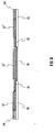
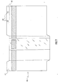
- FIG. 6 a cross section view of the continuous composite tape is shown, relating to the areas of transversal application of the heat-sealable varnish.
- the two materials making up the continuous composite tape are shown, as well as the three different layers of glue applied thereon: the laminated sheet material 36, the translucent material 18, the glue 32, the transversally applied heat-sealable varnish 37, 37', 37'' and the longitudinally applied heat-sealable varnish 34. From this figure is easy to see that the overall thickness of the composite tape is such as to result substantially uniform along the whole cross section thereof.
- This uniformity of thickness allows re-winding of the tape without any adhesion between one layer and the next, which, because of the strong pressure exercised during the re-winding operation, might cause the heat-sealable varnish to temper, due to a lack of uniform thickness.
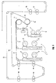
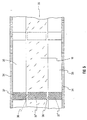
- FIG 7 a possible embodiment of a flat blank element is shown, from which a bag shaped wrapping can be obtained by means of folding and gluing operations, said element being made of the continuous composite tape of porous paper and transparent material having the general characteristics described above.
- the porous paper can have a basic weight (UNI 6440) preferably of between 30 and 100 gr/m 2 .
- a sheet element of this kind indicated as a whole in 40, has in particular a panel 41 with two holes 42.
- This panel is generally known as a "flap".
- the presence of a perforated flap on the mouth of the bag, once formed, is useful in order to improve insertion of the bags in groups into the hermetic sealing machine, after tempering of the transversal strip of heat-sealable resin.
- the groups of bags are anchored to the hooks thanks to the presence of the perforated flap, and are carried to the machine for introduction of the product and hermetic sealing.
- Said flap 41 thus allows the bags to be piled up, and to enter the high temperature food product insertion line and facilitate the operation of inserting the food product itself.
- FIG 8 shows a partial plan view from the side of a second embodiment of the machine according to the invention.
- the parts in common with the embodiment of figure 1 are indicated by dotted lines.
- the tape will be formed by three strips of laminated sheet material, for example porous paper, two side strips and one centre strip, between which two strips of translucent material, for example transparent film, are placed.
- means are provided, for example rotating reel means, indicated as a whole in 43, to carry the laminated sheet material in continuos tape form along a single line.
- the width of the tape of laminated sheet material unwinding from the reel 43 is double to that of the one provided in the first embodiment referred to in the machine of figure 1.
- the laminated sheet material unwinding from the reel 43 is carried along the line 44.
- This tape then passes through a first cutting group 45, shown schematically, the function of which is to cut the tape along its direction of movement so as to divide it longitudinally into three parts, two side parts and one central part, as will be indicated in the following with reference to figures 9A to 9E.
- first directing unit indicated schematically in 46 and made up preferably of rotating cylinders or directing and positioning bars, which aim is to re-position the side parts with respect to the central part, in a manner that will likewise be shown with reference to figures 9A to 9E.
- Second rotating reel means 47 are also provided to carry the translucent material, for example transparent film, in tape form along a single line.
- the width of the tape of translucent material unwinding from the reel 47 is double to that of the one provided in the first embodiment referred to in the machine of figure 1. In the preferred embodiment of the figure, the translucent material unwinding from the reel 47 is carried along the line 48.
- This tape then passes through a second cutting group 49, shown schematically, the function of which is to cut the tape along its direction of movement so as to divide it longitudinally into two parts, as will be indicated in the following with reference to figures 10A to 10E.
- the tape of translucent material then enters a second directing unit indicated schematically in 50 and made up preferably of rotating cylinders or directing and positioning bars, which aim is to re-position the two parts, in a manner that will likewise be shown with reference to figures 10A to 10E. From this point onward the tape proceeds as indicated with reference to figure 1.
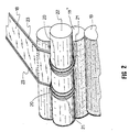
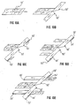
- FIGS. 9A to 9E a series of partial perspective views are shown, indicating in succession the operations that take place inside the first directing unit 46 of figure 8; in figure 9A a cutting device 51 is present to cut the tape of laminated sheet material along its direction of movement so as to divide it longitudinally into two side parts and a central part.
- first directing means 52 are shown, for example rotating cylinders or bars, to direct each of said side parts out at an angle of 90° in a direction perpendicular to the direction of movement before cutting.
- second directing means for example cylinders 53 are shown to subsequently reverse the sense of movement of each of said side parts by 180°.
- third directing means for example cylinders 54 are shown to subsequently direct each of said side parts out at an angle of 90° with respect to their direction of movement, in such a way that said side parts take on a direction parallel and in the opposite sense to the direction of movement before cutting.
- the arrangement of these third directing means 54 is such that each of the side parts of the tape of laminated sheet material can be separated from the central part thereof by a distance equal to approximately the width of the tape of translucent material which is subsequently to be bonded to the tape of laminated sheet material; the positioning of the third directing means 54 can be adjusted so as to adapt to different widths of the tape of translucent material.
- FIG 9E all the directing-positioning cylinders are shown, comprising also fourth directing means, for example cylinders 55, which subsequently reverse the sense of movement of each of said side parts by 180°, so that they take on a direction of movement parallel to and in the same sense as the direction of movement before cutting.
- fourth directing means for example cylinders 55, which subsequently reverse the sense of movement of each of said side parts by 180°, so that they take on a direction of movement parallel to and in the same sense as the direction of movement before cutting.
- FIGS. 10A to 10E a series of partial perspective views are shown, indicating in succession the operations that take place inside the second directing unit 50 of figure 8;
- a cutting device 51' is present to cut the tape of translucent material along its direction of movement so as to divide it longitudinally into two parts;
- fifth directing means for example cylinders or bars 52' are shown to direct each of said parts of the tape of translucent material out at an angle of 90° in a direction perpendicular to the direction of movement before cutting;
- FIG 10C in addition to the fifth directing means 52', sixth directing means, for example cylinders 53' are shown to subsequently reverse the sense of movement of each of said parts of the tape of translucent material by 180°;
- FIG 10D in addition to the fifth and sixth directing means 52', 53', seventh directing means, for example cylinders 54' are also shown to subsequently direct each of said parts of the tape of translucent material out at an angle of 90° with respect to their direction of movement before cutting.
- each of the parts of the tape of translucent material can be separated from the each other by a distance such to allow subsequent bonding thereof with between the central part and each of the side parts, respectively, of the tape of laminated sheet material; the positioning of the seventh directing means 54' being adjustable so as to adapt to different dimensions of both the tape of translucent material and the tape of laminated sheet material.
- all the directing means are shown, comprising eight directing means 55', which subsequently reverse the sense of movement of each of said parts of the tape of translucent material by 180°, so that they take on a direction of movement parallel to and in the same sense as the direction of movement before cutting.
- said first, second, third, fourth, fifth, sixth, seventh and eight directing means for directing the tape of laminated sheet material or of translucent material are preferably rotating cylinders or directing and positioning bars.
- transversal and longitudinal application take place in a single applicator group; a further variation provides cylindrical devices or spray guns for the spread of liquid products for the treatment and impregnation of the laminated sheet material or the translucent material.
- a third embodiment is that providing the formation of a series of openings in the laminated sheet material. These openings may have a wide variety of forms, according to the choices made during the design stage. The translucent material will then be bonded on the areas in which these openings have been made. Applications of glue, in particular heat-sealable varnish, both transversal and longitudinal, can occur on the laminated sheet material, for example before said bonding.
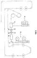
- Figure 11 shows a partial plan side view of said third embodiment of the machine according to the invention; in this embodiment there are provided first supply means, for example rotating reel means, indicated as a whole in 56, to supply the laminated sheet material in continuous tape form.
- first supply means for example rotating reel means, indicated as a whole in 56
- the laminated sheet material unrolling from the reel 56, is supplied along the line 57.
- a group 58 is then provided to blank the tape of laminated sheet material and to extract the blanked sections.
- This group is indicated only schematically, as its structure does not form a part of the present invention. Inside said group, openings will be made in the tape of laminated sheet material.
- the tape of laminated sheet material is made to pass through first and second applicator groups 59, 60 shown schematically in the figure, for a first and second application of glue, in particular heat-sealable varnish, thereon.
- the mode of application of the glue by the groups 59, 60 is identical to that outlined for the previous embodiments, which provide a group for transversal application of glue along preferred areas of the laminated sheet material and a group for longitudinal application of glue on the laminated sheet material.
- the tape of laminated sheet material is then made to pass through a group 61 for application of the film of translucent material on the areas of the tape of laminated sheet material from which the shaped section has been extracted; this film is supplied by second supply means, for example rotating reel means 62.
- the group 61 comprises means for the correct timing and correct positioning of the areas of transparent film.
- a further object of the present invention is a process for the formation of a continuous composite tape of material for the production of wrappings in which to pack food products, formed by laminated sheet material and translucent material, comprising the operations of bonding the laminated sheet material to the translucent material to form the continuous composite tape and applying glue on the continuous composite tape in a direction transversal to the direction of movement thereof, along preferred areas.
- a further object is a process for the formation of a continuous composite tape of material for the production of wrappings in which to pack food products, formed by laminated sheet material and translucent material, comprising the operations of applying glue on the laminated sheet material in a direction transversal to the direction of movement thereof, along preferred areas and bonding the laminated sheet material to the translucent material to form the continuous composite tape.
- Both processes can further comprise the operation of applying the glue on the laminated sheet material or on the translucent material along edge areas thereof, in a longitudinal direction with respect to their direction of movement, in such a way that it does not overlap the areas along which the glue is applied transversally.
- the processes can comprise the operation of blanking the tape of laminated sheet material and of extracting the blanked section.
- a further feature of said processes consists in the operations of:
- a further object of the present invention is a continuos composite tape formed with the process above defined.
- This tape is formed by strips of the translucent material alternating longitudinally with strips of the laminated sheet material.
- the continuos composite tape can be formed by laminated sheet material having a series of openings onto which the translucent material has been bonded.
- An example of a specific embodiment of the continuous composite tape according to the invention provides the use of paper with the following general characteristics: Basic weight (UNI 6440) gr/m 2 57 Thickness (UNI 6441) micron 110 Longitudinal tensile strength (UNI 6438/2) kN/m 2.8 Transversal tensile strength (UNI 6438/2) kN/m 1.4 Stretch % (UNI 6438/2): longitudinal breakage kN/m 1.8 transversal breakage kN/m 2.5 Resistance to burst (UNI 6443) kPa ⁇ m 2 /gr 2.8 Gurley factor (UNI 7629/4) ⁇ 5
- cellophane having the following general characteristics may be used:
- the cellophane, or any other type of translucent material used in place thereof be provided with microperforations on the part of its surface that is free of gluing substances.
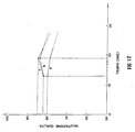
- figure 12 shows, as a specific example of embodiment, a series of degeneration curves for "Pugliese” or homebaked type bread, in which the horizontal axis shows the time (in hours) and the vertical axis shows a scale of product quality, evaluated by tasting. This scale goes from 50 (insufficient) to 100 (excellent).
- the curve "a” drawn with a continuous line, indicates the degeneration of bread cooled in a traditional way and subsequently introduced into a normal perforated film wrapping according to the prior art.
- the curve “b”, indicated by a dotted and dashed line shows the degeneration of bread which is introduced into the wrapping formed using the composite tape according to the invention straight from the oven, and therefore not cooled.
- curve “c” shown as an ordinary dotted line, indicates the degeneration of bread that is cooled in a traditional way and then introduced into the wrapping made using the composite tape according to the invention.
- curves "b” and “c”, which provide the use the composite tape according to the invention are greatly increased.
- curve "b” although it has characteristics of quality lower than those of curve "c”, enables production to be speeded up, as it does not require the time necessary to cool the product.
Applications Claiming Priority (3)
| Application Number | Priority Date | Filing Date | Title |
|---|---|---|---|
| IT95RM000647A IT1275612B1 (it) | 1995-09-28 | 1995-09-28 | Macchina e procedimento per realizzare un nastro composito continuo per la produzione di involucri per prodotti alimentari e nastro ed |
| ITRM950647 | 1995-09-28 | ||
| US08/825,343 US6090235A (en) | 1995-09-28 | 1997-03-28 | Process for formation of a continuous composite tape for the production of wrappings for food products |
Publications (3)
| Publication Number | Publication Date |
|---|---|
| EP0765744A2 true EP0765744A2 (fr) | 1997-04-02 |
| EP0765744A3 EP0765744A3 (fr) | 1997-12-17 |
| EP0765744B1 EP0765744B1 (fr) | 1999-06-30 |
Family
ID=26332087
Family Applications (1)
| Application Number | Title | Priority Date | Filing Date |
|---|---|---|---|
| EP96830485A Expired - Lifetime EP0765744B1 (fr) | 1995-09-28 | 1996-09-27 | Machine et procédé pour obtenir un ruban composite continu pour la production d'emballages de produits alimentaires, ainsi que le ruban et les emballages ainsi obtenus |
Country Status (7)
| Country | Link |
|---|---|
| US (1) | US6090235A (fr) |
| EP (1) | EP0765744B1 (fr) |
| AT (1) | ATE181698T1 (fr) |
| DE (1) | DE69603058T2 (fr) |
| ES (1) | ES2134582T3 (fr) |
| GR (1) | GR3031130T3 (fr) |
| IT (1) | IT1275612B1 (fr) |
Cited By (5)
| Publication number | Priority date | Publication date | Assignee | Title |
|---|---|---|---|---|
| EP0974450A2 (fr) * | 1998-07-23 | 2000-01-26 | Gala International Group | Sac à fenêtre et son procédé de production |
| EP1024093A1 (fr) * | 1999-01-26 | 2000-08-02 | Policarta S.r.l. | Feuille d'enveloppement biodégradable pour emballer des produits tels que des rouleaux de papier de toilette et méthode d'emballage correspondante |
| EP1031515A1 (fr) | 1999-02-26 | 2000-08-30 | Policarta S.r.l. | Feuille composite permeable à l'air |
| EP1813547A1 (fr) * | 2006-01-30 | 2007-08-01 | Policarta S.r.l. | Procédé d'emballage pour produits alimentaires |
| US8883236B2 (en) | 2006-07-13 | 2014-11-11 | Policarta S.R.L. | Wrapping for food products to be cooked in an oven |
Families Citing this family (4)
| Publication number | Priority date | Publication date | Assignee | Title |
|---|---|---|---|---|
| WO2003020607A1 (fr) * | 2001-09-04 | 2003-03-13 | Colgate-Palmolive Company | Enveloppe de pains de savon |
| US20080029584A1 (en) * | 2002-08-29 | 2008-02-07 | Todd Van Gordon | Soap Bar Wrapper |
| CA2508506A1 (fr) * | 2004-05-28 | 2005-11-28 | Packaging Dynamics Operating Company | Papier d'emballage alimentaire |
| ES2787723B2 (es) * | 2019-04-15 | 2021-02-19 | Marco Francesc Egea | Lamina de cierre de productos bobinados, metodo de fabricacion de la misma y maquina que lo ejecuta |
Citations (7)
| Publication number | Priority date | Publication date | Assignee | Title |
|---|---|---|---|---|
| US2511303A (en) * | 1946-09-09 | 1950-06-13 | Benj C Betner Company | Window bag and method and apparatus for making same |
| FR1434411A (fr) * | 1965-02-27 | 1966-04-08 | Procédé de fabrication d'un emballage semi-rigide pour produits liquides, pulvérulents ou autres | |
| FR2594805A1 (fr) * | 1986-02-24 | 1987-08-28 | Vauzelle Jean Marie | Feuille d'emballage et liasse realisee a l'aide de telles feuilles |
| US5165799A (en) * | 1978-10-10 | 1992-11-24 | Wood James R | Flexible side gusset square bottom bags |
| EP0520350A1 (fr) * | 1991-06-27 | 1992-12-30 | MECCANICA ROBECCHESE sas | Procédé et dispositif synchronisés pour le découpage de fenêtre dans des bandes continues, et pour l'application d'étiquettes sur les dites fenêtres |
| US5226735A (en) * | 1991-08-28 | 1993-07-13 | Daniel Beliveau | Perforated plastic bag for packaging fruits or vegetables |
| US5410857A (en) * | 1994-04-20 | 1995-05-02 | Vitex Packaging, Inc. | Process for making windowed form, fill and seal bags |
Family Cites Families (3)
| Publication number | Priority date | Publication date | Assignee | Title |
|---|---|---|---|---|
| US2425043A (en) * | 1943-03-03 | 1947-08-05 | Moore George Arlington | Container |
| US2668769A (en) * | 1951-09-27 | 1954-02-09 | Riegel Paper Corp | Paper package and method of manufacture |
| US5195829A (en) * | 1990-10-26 | 1993-03-23 | Golden Valley Microwave Foods Inc. | Flat bottomed stand-up microwave corn popping bag |
-
1995
- 1995-09-28 IT IT95RM000647A patent/IT1275612B1/it active IP Right Grant
-
1996
- 1996-09-27 AT AT96830485T patent/ATE181698T1/de active
- 1996-09-27 ES ES96830485T patent/ES2134582T3/es not_active Expired - Lifetime
- 1996-09-27 EP EP96830485A patent/EP0765744B1/fr not_active Expired - Lifetime
- 1996-09-27 DE DE69603058T patent/DE69603058T2/de not_active Expired - Lifetime
-
1997
- 1997-03-28 US US08/825,343 patent/US6090235A/en not_active Expired - Lifetime
-
1999
- 1999-09-01 GR GR990402215T patent/GR3031130T3/el unknown
Patent Citations (7)
| Publication number | Priority date | Publication date | Assignee | Title |
|---|---|---|---|---|
| US2511303A (en) * | 1946-09-09 | 1950-06-13 | Benj C Betner Company | Window bag and method and apparatus for making same |
| FR1434411A (fr) * | 1965-02-27 | 1966-04-08 | Procédé de fabrication d'un emballage semi-rigide pour produits liquides, pulvérulents ou autres | |
| US5165799A (en) * | 1978-10-10 | 1992-11-24 | Wood James R | Flexible side gusset square bottom bags |
| FR2594805A1 (fr) * | 1986-02-24 | 1987-08-28 | Vauzelle Jean Marie | Feuille d'emballage et liasse realisee a l'aide de telles feuilles |
| EP0520350A1 (fr) * | 1991-06-27 | 1992-12-30 | MECCANICA ROBECCHESE sas | Procédé et dispositif synchronisés pour le découpage de fenêtre dans des bandes continues, et pour l'application d'étiquettes sur les dites fenêtres |
| US5226735A (en) * | 1991-08-28 | 1993-07-13 | Daniel Beliveau | Perforated plastic bag for packaging fruits or vegetables |
| US5410857A (en) * | 1994-04-20 | 1995-05-02 | Vitex Packaging, Inc. | Process for making windowed form, fill and seal bags |
Cited By (6)
| Publication number | Priority date | Publication date | Assignee | Title |
|---|---|---|---|---|
| EP0974450A2 (fr) * | 1998-07-23 | 2000-01-26 | Gala International Group | Sac à fenêtre et son procédé de production |
| EP0974450A3 (fr) * | 1998-07-23 | 2000-04-26 | Gala International Group | Sac à fenêtre et son procédé de production |
| EP1024093A1 (fr) * | 1999-01-26 | 2000-08-02 | Policarta S.r.l. | Feuille d'enveloppement biodégradable pour emballer des produits tels que des rouleaux de papier de toilette et méthode d'emballage correspondante |
| EP1031515A1 (fr) | 1999-02-26 | 2000-08-30 | Policarta S.r.l. | Feuille composite permeable à l'air |
| EP1813547A1 (fr) * | 2006-01-30 | 2007-08-01 | Policarta S.r.l. | Procédé d'emballage pour produits alimentaires |
| US8883236B2 (en) | 2006-07-13 | 2014-11-11 | Policarta S.R.L. | Wrapping for food products to be cooked in an oven |
Also Published As
| Publication number | Publication date |
|---|---|
| DE69603058T2 (de) | 1999-12-09 |
| ITRM950647A0 (fr) | 1995-09-28 |
| ATE181698T1 (de) | 1999-07-15 |
| ES2134582T3 (es) | 1999-10-01 |
| DE69603058D1 (de) | 1999-08-05 |
| EP0765744B1 (fr) | 1999-06-30 |
| IT1275612B1 (it) | 1997-10-14 |
| GR3031130T3 (en) | 1999-12-31 |
| ITRM950647A1 (it) | 1997-03-28 |
| US6090235A (en) | 2000-07-18 |
| EP0765744A3 (fr) | 1997-12-17 |
Similar Documents
| Publication | Publication Date | Title |
|---|---|---|
| US5804265A (en) | Functional freezer storage bag | |
| US3566752A (en) | Method of forming a tear strip on a packaging sheet | |
| US4895611A (en) | Method and apparatus for making non-roping thermoplastic draw tape for thermplastic bags | |
| US7798715B2 (en) | Composite breathable produce bag with a reinforced mesh sidewall | |
| EP0025006B1 (fr) | Dispositif de procédé pour l'application d'adhesif fluide | |
| US3399096A (en) | Method and apparatus for forming reinforced edges in packaging blanks | |
| US5702552A (en) | Method for making a pleated expandable cellular product for window coverings | |
| US2803578A (en) | Extensible zigzag pack and method of making same | |
| US5766399A (en) | Closable bag and method of making same | |
| EP0765744B1 (fr) | Machine et procédé pour obtenir un ruban composite continu pour la production d'emballages de produits alimentaires, ainsi que le ruban et les emballages ainsi obtenus | |
| US4863287A (en) | Waxed bag with wax-free area | |
| CA2246277C (fr) | Sac de conservation au congelateur | |
| US2673495A (en) | Method and apparatus for making bags | |
| CN111757810A (zh) | 形成改进的保护性生态友好囊袋的方法和由其制成的包装和产品 | |
| US2062265A (en) | Method of making sealed bags | |
| US5968310A (en) | Closable bag and method apparatus for making same | |
| US1871687A (en) | Waxing of paper and wrapping of articles therein | |
| US3266710A (en) | Multiwall bag and method of making same | |
| CA2173930A1 (fr) | Sacs a echantillons et procede et dispositif de fabrication | |
| JP4118568B2 (ja) | ヒダ付き縦ピロー包装体の製造方法 | |
| US4822437A (en) | Method and apparatus for making non-roping thermoplastic draw tape for thermoplastic bags | |
| CN2254060Y (zh) | 纸袋口密封装置 | |
| US3015996A (en) | Bags and method and machine for making same | |
| GB2097361A (en) | Bag | |
| US4119452A (en) | Method of coating and cutting wrapper blanks |
Legal Events
| Date | Code | Title | Description |
|---|---|---|---|
| PUAI | Public reference made under article 153(3) epc to a published international application that has entered the european phase |
Free format text: ORIGINAL CODE: 0009012 |
|
| AK | Designated contracting states |
Kind code of ref document: A2 Designated state(s): AT BE CH DE DK ES FR GB GR LI LU NL PT |
|
| PUAL | Search report despatched |
Free format text: ORIGINAL CODE: 0009013 |
|
| AK | Designated contracting states |
Kind code of ref document: A3 Designated state(s): AT BE CH DE DK ES FR GB GR LI LU NL PT |
|
| 17P | Request for examination filed |
Effective date: 19971219 |
|
| 17Q | First examination report despatched |
Effective date: 19980407 |
|
| GRAG | Despatch of communication of intention to grant |
Free format text: ORIGINAL CODE: EPIDOS AGRA |
|
| GRAG | Despatch of communication of intention to grant |
Free format text: ORIGINAL CODE: EPIDOS AGRA |
|
| GRAH | Despatch of communication of intention to grant a patent |
Free format text: ORIGINAL CODE: EPIDOS IGRA |
|
| RAP3 | Party data changed (applicant data changed or rights of an application transferred) |
Owner name: POLICARTA S.R.L. |
|
| GRAH | Despatch of communication of intention to grant a patent |
Free format text: ORIGINAL CODE: EPIDOS IGRA |
|
| GRAA | (expected) grant |
Free format text: ORIGINAL CODE: 0009210 |
|
| AK | Designated contracting states |
Kind code of ref document: B1 Designated state(s): AT BE CH DE DK ES FR GB GR LI LU NL PT |
|
| PG25 | Lapsed in a contracting state [announced via postgrant information from national office to epo] |
Ref country code: NL Free format text: LAPSE BECAUSE OF FAILURE TO SUBMIT A TRANSLATION OF THE DESCRIPTION OR TO PAY THE FEE WITHIN THE PRESCRIBED TIME-LIMIT Effective date: 19990630 Ref country code: BE Free format text: LAPSE BECAUSE OF FAILURE TO SUBMIT A TRANSLATION OF THE DESCRIPTION OR TO PAY THE FEE WITHIN THE PRESCRIBED TIME-LIMIT Effective date: 19990630 |
|
| REF | Corresponds to: |
Ref document number: 181698 Country of ref document: AT Date of ref document: 19990715 Kind code of ref document: T |
|
| REG | Reference to a national code |
Ref country code: CH Ref legal event code: EP |
|
| REF | Corresponds to: |
Ref document number: 69603058 Country of ref document: DE Date of ref document: 19990805 |
|
| ET | Fr: translation filed | ||
| PG25 | Lapsed in a contracting state [announced via postgrant information from national office to epo] |
Ref country code: LU Free format text: LAPSE BECAUSE OF NON-PAYMENT OF DUE FEES Effective date: 19990927 |
|
| PG25 | Lapsed in a contracting state [announced via postgrant information from national office to epo] |
Ref country code: PT Free format text: LAPSE BECAUSE OF FAILURE TO SUBMIT A TRANSLATION OF THE DESCRIPTION OR TO PAY THE FEE WITHIN THE PRESCRIBED TIME-LIMIT Effective date: 19990930 Ref country code: DK Free format text: LAPSE BECAUSE OF FAILURE TO SUBMIT A TRANSLATION OF THE DESCRIPTION OR TO PAY THE FEE WITHIN THE PRESCRIBED TIME-LIMIT Effective date: 19990930 |
|
| REG | Reference to a national code |
Ref country code: CH Ref legal event code: NV Representative=s name: PATENTANWAELTE SCHAAD, BALASS, MENZL & PARTNER AG |
|
| REG | Reference to a national code |
Ref country code: ES Ref legal event code: FG2A Ref document number: 2134582 Country of ref document: ES Kind code of ref document: T3 |
|
| NLV1 | Nl: lapsed or annulled due to failure to fulfill the requirements of art. 29p and 29m of the patents act | ||
| PLBE | No opposition filed within time limit |
Free format text: ORIGINAL CODE: 0009261 |
|
| STAA | Information on the status of an ep patent application or granted ep patent |
Free format text: STATUS: NO OPPOSITION FILED WITHIN TIME LIMIT |
|
| 26N | No opposition filed | ||
| REG | Reference to a national code |
Ref country code: GB Ref legal event code: IF02 |
|
| PGFP | Annual fee paid to national office [announced via postgrant information from national office to epo] |
Ref country code: GB Payment date: 20071023 Year of fee payment: 12 |
|
| GBPC | Gb: european patent ceased through non-payment of renewal fee |
Effective date: 20080927 |
|
| PG25 | Lapsed in a contracting state [announced via postgrant information from national office to epo] |
Ref country code: GB Free format text: LAPSE BECAUSE OF NON-PAYMENT OF DUE FEES Effective date: 20080927 |
|
| PGFP | Annual fee paid to national office [announced via postgrant information from national office to epo] |
Ref country code: CH Payment date: 20110923 Year of fee payment: 16 |
|
| PGFP | Annual fee paid to national office [announced via postgrant information from national office to epo] |
Ref country code: GR Payment date: 20120926 Year of fee payment: 17 |
|
| PGFP | Annual fee paid to national office [announced via postgrant information from national office to epo] |
Ref country code: ES Payment date: 20120926 Year of fee payment: 17 Ref country code: DE Payment date: 20120921 Year of fee payment: 17 |
|
| PGFP | Annual fee paid to national office [announced via postgrant information from national office to epo] |
Ref country code: FR Payment date: 20121010 Year of fee payment: 17 |
|
| PGFP | Annual fee paid to national office [announced via postgrant information from national office to epo] |
Ref country code: AT Payment date: 20120912 Year of fee payment: 17 |
|
| REG | Reference to a national code |
Ref country code: DE Ref legal event code: R119 Ref document number: 69603058 Country of ref document: DE |
|
| REG | Reference to a national code |
Ref country code: CH Ref legal event code: PL |
|
| REG | Reference to a national code |
Ref country code: AT Ref legal event code: MM01 Ref document number: 181698 Country of ref document: AT Kind code of ref document: T Effective date: 20130927 |
|
| REG | Reference to a national code |
Ref country code: GR Ref legal event code: ML Ref document number: 990402215 Country of ref document: GR Effective date: 20140403 |
|
| REG | Reference to a national code |
Ref country code: FR Ref legal event code: ST Effective date: 20140530 |
|
| PG25 | Lapsed in a contracting state [announced via postgrant information from national office to epo] |
Ref country code: LI Free format text: LAPSE BECAUSE OF NON-PAYMENT OF DUE FEES Effective date: 20130930 Ref country code: CH Free format text: LAPSE BECAUSE OF NON-PAYMENT OF DUE FEES Effective date: 20130930 |
|
| PG25 | Lapsed in a contracting state [announced via postgrant information from national office to epo] |
Ref country code: GR Free format text: LAPSE BECAUSE OF NON-PAYMENT OF DUE FEES Effective date: 20140403 Ref country code: DE Free format text: LAPSE BECAUSE OF NON-PAYMENT OF DUE FEES Effective date: 20140401 Ref country code: FR Free format text: LAPSE BECAUSE OF NON-PAYMENT OF DUE FEES Effective date: 20130930 Ref country code: AT Free format text: LAPSE BECAUSE OF NON-PAYMENT OF DUE FEES Effective date: 20130927 |
|
| REG | Reference to a national code |
Ref country code: DE Ref legal event code: R079 Ref document number: 69603058 Country of ref document: DE Free format text: PREVIOUS MAIN CLASS: B32B0031120000 Ipc: B32B0037000000 |
|
| REG | Reference to a national code |
Ref country code: ES Ref legal event code: FD2A Effective date: 20141007 |
|
| REG | Reference to a national code |
Ref country code: DE Ref legal event code: R119 Ref document number: 69603058 Country of ref document: DE Effective date: 20140401 Ref country code: DE Ref legal event code: R079 Ref document number: 69603058 Country of ref document: DE Free format text: PREVIOUS MAIN CLASS: B32B0031120000 Ipc: B32B0037000000 Effective date: 20140924 |
|
| PG25 | Lapsed in a contracting state [announced via postgrant information from national office to epo] |
Ref country code: ES Free format text: LAPSE BECAUSE OF NON-PAYMENT OF DUE FEES Effective date: 20130928 |