EP0765632B1 - Method and apparatus for respiration monitoring - Google Patents
Method and apparatus for respiration monitoring Download PDFInfo
- Publication number
- EP0765632B1 EP0765632B1 EP96113850A EP96113850A EP0765632B1 EP 0765632 B1 EP0765632 B1 EP 0765632B1 EP 96113850 A EP96113850 A EP 96113850A EP 96113850 A EP96113850 A EP 96113850A EP 0765632 B1 EP0765632 B1 EP 0765632B1
- Authority
- EP
- European Patent Office
- Prior art keywords
- current
- electrodes
- examination
- patient
- accordance
- Prior art date
- Legal status (The legal status is an assumption and is not a legal conclusion. Google has not performed a legal analysis and makes no representation as to the accuracy of the status listed.)
- Expired - Lifetime
Links
Images


Classifications
-
- A—HUMAN NECESSITIES
- A61—MEDICAL OR VETERINARY SCIENCE; HYGIENE
- A61B—DIAGNOSIS; SURGERY; IDENTIFICATION
- A61B5/00—Measuring for diagnostic purposes; Identification of persons
- A61B5/08—Measuring devices for evaluating the respiratory organs
- A61B5/085—Measuring impedance of respiratory organs or lung elasticity
- A61B5/086—Measuring impedance of respiratory organs or lung elasticity by impedance pneumography
Definitions
- the present invention relates to monitoring respirations of a patient, and more specifically to impedance pneumography, which is a technique for monitoring respirations by monitoring changes in electrical impedance caused by the expansion and contraction of the thoracic cavity of the patient during respiration.
- a differential, constant amplitude AC examination current is applied to the body of a patient for detecting patient respirations by measuring changes in the transthoracic impedance of the patient.
- the examination current is applied to the patient by two of the electrodes normally used for ECG monitoring.
- the examination current is passed through the thoracic cavity of the patient and, due to the constant amplitude examination current passing through a transthoracic impedance that changes with patient respirations, voltage modulations are created at the ECG electrodes in accordance with the patient respirations.
- the resulting voltage modulations are typically detected by a synchronous voltage detector, connected to the same pair of electrodes as was used for applying the examination current, such as the right arm (RA) and left arm (LA) electrodes.
- the cables used for connecting the examination current and voltage detector to the patient contain capacitive reactances which tends to shunt a portion of the examination current around the patient.
- capacitive reactances which tends to shunt a portion of the examination current around the patient.
- One effect of this shunting is that the system gain, as expressed in Volts/Ohm, will have a dependency on the baseline level of the transthoracic impedance, as well as the level of any impedance placed in series with the patient, such as resistances for protecting the monitoring circuitry from defibrillator voltages which may be applied to the patient.
- This dependency makes detecting the small respiration induced changes in impedance more difficult (that is, such a dependency making it difficult to set absolute signal detection threshold levels).
- Another effect is that the induced voltage becomes sensitive to changes in the frequency of the examination current.
- any phase or frequency jitter in the examination current signals, or the clock signals used to detect the examination current will be converted to a voltage noise during detection by the synchronous voltage detector.
- the above-noted shunting of the examination current, changes in the system gain, and voltage noise result in signal artifacts in the induced voltage modulations which reduce the accuracy of the respiration detection circuitry.
- a prior art respiration monitor manufactured by Hewlett-Packard (believed to be sold under the trademark CLOVER) applies a fixed frequency sine wave to an impedance bridge, one leg of which is connected to the thoracic cavity of a patient via a transformer.
- the output of the bridge is fed to a synchronous detector for developing the respiration signal in accordance with known techniques.
- the technique undesirably requires the use of a transformer, which is bulky and not well suited for incorporation with integrated circuit technology. Additionally, this technique requires a sinewave examination current, which is somewhat difficult and costly to generate using digital circuitry.
- an apparatus for monitoring the expansion and contraction of the thoracic cavity of a patient caused by respiration comprising:
- FIG 1 illustrates a prior art respiration monitor 8 wherein a differential current source 10 generates two identical, but differential (180° out of phase), AC examination currents.
- the differential currents are applied to patient mounted electrodes 12 and 14, respectively, via a patient connected cable 16.
- the electrodes are of the type used for EKG monitoring, and patient cable 16 is the EKG cable used to connect the EKG electrodes to an EKG monitor.
- EKG signal processing circuitry (not shown) would also be connected to cable 16 in parallel with respiration circuitry 18, for developing and displaying EKG waveforms, as well known.
- the body of a patient P presents a varying impedance Z between electrodes 12 and 14, the variations in the patient impedance corresponding to the expansion and contraction of the transthoracic cavity of the patient in response to patient respirations.
- Respiration circuitry 18 within the monitor is connected to the electrodes 12 and 14 via cable 16 for sensing amplitude modulations of a voltage developed between electrodes 12 and 14 due to the applied AC examination current and the patient respirations.
- these sensed amplitude modulations are processed for developing a respiration signal which may be used for display and/or alarm monitoring of the respirations of the patient.
- C C the effective capacitance of cable 16, and C B and R P , comprising a DC blocking capacitor and a high voltage protection resistor, respectively.
- the effective capacitance C C of cable 16 tends to shunt a portion of the AC examination current around, rather than through, the patient.
- One major effect of this shunting is a reduced signal level of the induced voltage modulations, thereby reducing the ability to accurately monitor the changes in patient impedance, which is on the order of only 1 or 2 Ohms out of approximately 600 to 6000 Ohms of patient impedance. At approximately 5000-6000 Ohms of patient impedance, current shunting by the cable is significant.
- FIG 2 a block diagram of a respiration monitor constructed in accordance with the principles of the present invention is shown. Circuits and components that are substantially the same in Figures 1 and 2 are similarly numbered. Basically, there are at least two improvements over the prior art. Firstly, compensation networks 20 and 22 are incorporated with the differential outputs of current source 10 forming a modified current source 10', and secondly, in the preferred embodiment, the differential current source is provided using a switched "flying" capacitor circuit arrangement.
- a differential current source 11 provides a square wave examination current 24 (of, for example, ⁇ 100 ⁇ A), and compensation networks 20 and 22 modify the examination current so as to develop a compensated current at the respective outputs of current source 11' which has an overshoot at its leading edges, as illustrated by waveform 26.
- Waveform 28 is illustrative of the voltage developed across the patient in response to application to the patient of the compensated examination current, which voltage is transmitted to the respiration detection circuits 18 via cable 16. Note that the level transitions in waveform 28 are substantially rectangular, wherein if the compensated examination current, as illustrated by waveform 26, were not provided, a portion of the examination current will initially be shunted across the patient by the capacitance C c of cable 16, and then slowly increase thereafter.
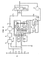
- FIG 3 illustrates partially in block diagram form and partially in detailed schematic diagram form a respiration monitor constructed in accordance with the principles of the present invention, including the compensated current source 11'.
- the compensated current source 11' develops two identical differential AC currents that are 180° out of phase, and basically comprises two identical current sources, details of only one-half of the circuitry will be described.
- a voltage reference 50 comprises series connected diodes D 1 and D 2 , which are forward biased via resistors R 1 and R 2 connected to power supply voltages of + 5 volts and - 5 volts, respectively.
- First and second substantially identical switching arrangements 52 and 54 are simultaneously coupled to the positive and negative sides, respectively, of voltage reference source 50 for developing in a complimentary manner first and second differential voltage signals, respectively.
- a system clock (not shown) provides complimentary (180° out of phase) clock signals CLK + and CLK - , which are provided to switching arrangements 52 and 54, respectively.
- the first and second differential voltage signals provided by switching arrangements 52 and 54 are then converted to current signals via first and second voltage to current (V/I) converters 56 and 58, respectively.
- the examination current signals developed at the output of converters 56 and 58 are modified by compensation networks 60 and 62, respectively, before being applied to the patient via the previously described blocking capacitor, high voltage protection resistor, patient cable and patient electrodes.
- the modification is by an amount sufficient to substantially compensate for the undesirable shunting of the examination current around the patient.
- voltage reference 50 provides a low impedance reference source for charging a "flying" capacitor C 9 via a clocked integrated circuit switch arrangement 54, which includes switch portions 54A that are normally closed in response to the CLK - clock signals, as shown.
- switch portion 54A On the first half-cycle of the CLK - clock signal, switch portion 54A connects capacitor C 9 across reference voltage source 50.
- switch portion 54B On the second half-cycle of CLK - clock signal, switch portion 54B connects capacitor C 9 across capacitor C 10 , thereby maintaining a steady state voltage on capacitor C 10 at a value equal to the reference voltage.
- a reversing switch arrangement comprising switches 54C and 54D alternately reverses the polarity of the voltage developed across capacitor C 10 for application to a voltage to current (V/I) converter amplifier 58.
- Amplifier 58 forces the voltage on capacitor C 10 to appear across compensation network 62.
- the timing of switches 54C and 54D are controlled by the CLK - clock signal, with normal switch positions as shown in Figure 3.
- the output of amplifier 58 is provided as the examination current after being modified via compensation network 62.
- Network 62 comprises a parallel connection of R 4 and C 14 .
- Compensation of the current source is achieved as follows. At the instant the voltage across the compensation network 62 changes polarity, due to the operation of reversing switch 54C/54D, a transient current substantially larger than the steady state current is created by a rapid charging action of capacitor C 14 by amplifier 58. This transient current is used to rapidly charge the distributed capacitance in patient cable 16. This transient current surge then decays at an exponential rate, as determined by the RC time constant of R 4 and C 14 of compensation network 62. If the product of R 4 and C 14 is made to be substantially equal to the RC product formed by the transthoracic impedance of the patient and the distributed capacitance of the patient cable, then the effects of cable capacitance can be substantially diminished.
- Synchronous detector 64 operates in a manner well known to those of ordinary skill in the art, and is responsive to the CLK + and CLK - clock signals for detecting the AC voltage, with amplitude modulations corresponding to respirations, generated at its output.
- the setting of R 4 and C 14 can be made at the factory during manufacture, using fixed values that provide appropriate compensation for typical patients, as determined by trial and error during circuit design.
- the output of the synchronous detector portion of respiration circuit 18 could be monitored for a predetermined output level while C 14 is manually adjusted by the user.
- capacitor C 14 can be made automatic by using a varactor diode as C 14 and developing a control signal from the output of the synchronous detector which is applied in a feedback manner to diode C 14 .
- current source 11 is illustrated using a switched capacitor arrangement, other arrangements for generating a current source are also possible, such as a large valve resistor, but which are not as advantageous as the illustrated embodiment. All such changes, modifications, variations and other uses and applications which do not depart from the scope of the invention are deemed to be covered by the invention which is limited only by the claims which follow.
Landscapes
- Health & Medical Sciences (AREA)
- Life Sciences & Earth Sciences (AREA)
- Pulmonology (AREA)
- Biomedical Technology (AREA)
- Medical Informatics (AREA)
- Biophysics (AREA)
- Pathology (AREA)
- Engineering & Computer Science (AREA)
- Physiology (AREA)
- Heart & Thoracic Surgery (AREA)
- Physics & Mathematics (AREA)
- Molecular Biology (AREA)
- Surgery (AREA)
- Animal Behavior & Ethology (AREA)
- General Health & Medical Sciences (AREA)
- Public Health (AREA)
- Veterinary Medicine (AREA)
- Measurement Of The Respiration, Hearing Ability, Form, And Blood Characteristics Of Living Organisms (AREA)
- Respiratory Apparatuses And Protective Means (AREA)
Abstract
Description
- The present invention relates to monitoring respirations of a patient, and more specifically to impedance pneumography, which is a technique for monitoring respirations by monitoring changes in electrical impedance caused by the expansion and contraction of the thoracic cavity of the patient during respiration.
- Typically, a differential, constant amplitude AC examination current is applied to the body of a patient for detecting patient respirations by measuring changes in the transthoracic impedance of the patient. The examination current is applied to the patient by two of the electrodes normally used for ECG monitoring. The examination current is passed through the thoracic cavity of the patient and, due to the constant amplitude examination current passing through a transthoracic impedance that changes with patient respirations, voltage modulations are created at the ECG electrodes in accordance with the patient respirations. The resulting voltage modulations are typically detected by a synchronous voltage detector, connected to the same pair of electrodes as was used for applying the examination current, such as the right arm (RA) and left arm (LA) electrodes.
- The cables used for connecting the examination current and voltage detector to the patient contain capacitive reactances which tends to shunt a portion of the examination current around the patient. One effect of this shunting is that the system gain, as expressed in Volts/Ohm, will have a dependency on the baseline level of the transthoracic impedance, as well as the level of any impedance placed in series with the patient, such as resistances for protecting the monitoring circuitry from defibrillator voltages which may be applied to the patient. This dependency makes detecting the small respiration induced changes in impedance more difficult (that is, such a dependency making it difficult to set absolute signal detection threshold levels). Another effect is that the induced voltage becomes sensitive to changes in the frequency of the examination current. Any phase or frequency jitter in the examination current signals, or the clock signals used to detect the examination current, will be converted to a voltage noise during detection by the synchronous voltage detector. The above-noted shunting of the examination current, changes in the system gain, and voltage noise result in signal artifacts in the induced voltage modulations which reduce the accuracy of the respiration detection circuitry.
- It is an object of the present invention to provide an AC examination current source which will solve these undesirable effects, while providing a current source which is relatively low in cost, which will present minimum load to ECG signals acquired by the electrodes, and able to be easily manufactured using integrated circuit technology.
- A prior art respiration monitor manufactured by Hewlett-Packard (believed to be sold under the trademark CLOVER) applies a fixed frequency sine wave to an impedance bridge, one leg of which is connected to the thoracic cavity of a patient via a transformer.
- The output of the bridge is fed to a synchronous detector for developing the respiration signal in accordance with known techniques.
- The technique undesirably requires the use of a transformer, which is bulky and not well suited for incorporation with integrated circuit technology. Additionally, this technique requires a sinewave examination current, which is somewhat difficult and costly to generate using digital circuitry.
- According to the present invention there is provided an apparatus for monitoring the expansion and contraction of the thoracic cavity of a patient caused by respiration, comprising:
- generating means for generating an AC examination current signal;
- electrodes for applying said examination current signal to the patient;
- coupling means for applying said examination current signal to the electrodes so that a portion of said examination current passes through the electrodes, while a portion of said current does not pass through the electrodes but is shunted due to the effective capacitance of the coupling means; and
- detecting means coupled to said coupling means for detecting an amplitude modulated voltage signal developed across said electrodes in response to said application of the examination current and variation of the impedance presented to said electrodes; characterised by current modifying means coupled with the generating means for modifying the AC examination current during application to the electrodes so as to develop a compensated current which has an overshoot at its leading edges so that said portion of the examination current which does not pass through said electrodes is at least partially compensated.
-
- Preferred features of the invention are recited in the dependent claims.
- Figure 1 illustrates in block diagram form a prior art respiration monitor;
- Figure 2 illustrates in block diagram form a respiration monitor constructed in accordance with the principles of the present invention;
- Figure 3 illustrates partially in block diagram form and partially in schematic diagram form the respiration monitor shown in Figure 2; and
- Figure 4 illustrates in block diagram form the functional operation of a portion of the schematic shown in Figure 3.
-
- Figure 1 illustrates a prior
art respiration monitor 8 wherein a differentialcurrent source 10 generates two identical, but differential (180° out of phase), AC examination currents. The differential currents are applied to patient mountedelectrodes cable 16. Typically, the electrodes are of the type used for EKG monitoring, andpatient cable 16 is the EKG cable used to connect the EKG electrodes to an EKG monitor. In this case, EKG signal processing circuitry (not shown) would also be connected tocable 16 in parallel withrespiration circuitry 18, for developing and displaying EKG waveforms, as well known. As also well known, the body of a patient P presents a varying impedance Z betweenelectrodes Respiration circuitry 18 within the monitor is connected to theelectrodes cable 16 for sensing amplitude modulations of a voltage developed betweenelectrodes cable 16, and CB and RP, comprising a DC blocking capacitor and a high voltage protection resistor, respectively. - The effective capacitance CC of
cable 16 tends to shunt a portion of the AC examination current around, rather than through, the patient. One major effect of this shunting is a reduced signal level of the induced voltage modulations, thereby reducing the ability to accurately monitor the changes in patient impedance, which is on the order of only 1 or 2 Ohms out of approximately 600 to 6000 Ohms of patient impedance. At approximately 5000-6000 Ohms of patient impedance, current shunting by the cable is significant. Other undesirable and related effects of the cable capacitance CC are the variation and gain, as expressed in Volts/Ohm, and the conversion into voltage variations by the synchronous detector of frequency and/or phase jitter in the examination current, as previously noted in the Background portion of this specification. - In Figure 2, a block diagram of a respiration monitor constructed in accordance with the principles of the present invention is shown. Circuits and components that are substantially the same in Figures 1 and 2 are similarly numbered. Basically, there are at least two improvements over the prior art. Firstly,
compensation networks current source 10 forming a modified current source 10', and secondly, in the preferred embodiment, the differential current source is provided using a switched "flying" capacitor circuit arrangement. - As shown in Figure 2, a differential
current source 11 provides a square wave examination current 24 (of, for example, ±100µA), andcompensation networks current source 11' which has an overshoot at its leading edges, as illustrated bywaveform 26. Waveform 28 is illustrative of the voltage developed across the patient in response to application to the patient of the compensated examination current, which voltage is transmitted to therespiration detection circuits 18 viacable 16. Note that the level transitions in waveform 28 are substantially rectangular, wherein if the compensated examination current, as illustrated bywaveform 26, were not provided, a portion of the examination current will initially be shunted across the patient by the capacitance Cc ofcable 16, and then slowly increase thereafter. This undesired effect of the cable capacitance, if left uncompensated, would result in a voltage waveform 28 having degraded leading edges at the signal level transitions, such as shown by the curved dashed-line portions in waveform 28. These curved portions indicate a reduced amplitude level voltage signal (i.e., one with a reduced S/N) into the respiration detector (as well as an unwanted amplitude level variation), which, as previously noted, can result in monitoring inaccuracies when developing the respiration signal.Compensation networks respiration circuitry 18. - Figure 3 illustrates partially in block diagram form and partially in detailed schematic diagram form a respiration monitor constructed in accordance with the principles of the present invention, including the compensated
current source 11'. Note, since the compensatedcurrent source 11' develops two identical differential AC currents that are 180° out of phase, and basically comprises two identical current sources, details of only one-half of the circuitry will be described. In this regard, in conjunction with this description, reference should also be made to the functional block diagram shown in Figure 4, which functionally describes the operation of one-half of the switching arrangement formingcurrent source 11. Avoltage reference 50 comprises series connected diodes D1 and D2, which are forward biased via resistors R1 and R2 connected to power supply voltages of + 5 volts and - 5 volts, respectively. First and second substantiallyidentical switching arrangements voltage reference source 50 for developing in a complimentary manner first and second differential voltage signals, respectively. A system clock (not shown) provides complimentary (180° out of phase) clock signals CLK+ and CLK-, which are provided to switchingarrangements switching arrangements converters - In accordance with the principles of the invention, the examination current signals developed at the output of
converters compensation networks - Referring again to Figures 3 and 4,
voltage reference 50 provides a low impedance reference source for charging a "flying" capacitor C9 via a clocked integratedcircuit switch arrangement 54, which includesswitch portions 54A that are normally closed in response to the CLK- clock signals, as shown. On the first half-cycle of the CLK- clock signal,switch portion 54A connects capacitor C9 acrossreference voltage source 50. On the second half-cycle of CLK- clock signal, switch portion 54B connects capacitor C9 across capacitor C10, thereby maintaining a steady state voltage on capacitor C10 at a value equal to the reference voltage. A reversing switcharrangement comprising switches converter amplifier 58. Amplifier 58 forces the voltage on capacitor C10 to appear acrosscompensation network 62. The timing ofswitches amplifier 58 is provided as the examination current after being modified viacompensation network 62.Network 62 comprises a parallel connection of R4 and C14. - Compensation of the current source is achieved as follows. At the instant the voltage across the
compensation network 62 changes polarity, due to the operation of reversingswitch 54C/54D, a transient current substantially larger than the steady state current is created by a rapid charging action of capacitor C14 byamplifier 58. This transient current is used to rapidly charge the distributed capacitance inpatient cable 16. This transient current surge then decays at an exponential rate, as determined by the RC time constant of R4 and C14 ofcompensation network 62. If the product of R4 and C14 is made to be substantially equal to the RC product formed by the transthoracic impedance of the patient and the distributed capacitance of the patient cable, then the effects of cable capacitance can be substantially diminished. The extra current provided bycurrent source 11' compensates for the amount of examination current that shunts around the patient due to cable capacitance CC, rather than flowing through his transthoracic cavity. This will maximize the S/N of the developed voltage modulation signal applied to thesynchronous detector 64 at the input ofrespiration detection circuitry 18.Synchronous detector 64 operates in a manner well known to those of ordinary skill in the art, and is responsive to the CLK+ and CLK- clock signals for detecting the AC voltage, with amplitude modulations corresponding to respirations, generated at its output. - The setting of R4 and C14 can be made at the factory during manufacture, using fixed values that provide appropriate compensation for typical patients, as determined by trial and error during circuit design. Alternatively, the output of the synchronous detector portion of
respiration circuit 18 could be monitored for a predetermined output level while C14 is manually adjusted by the user. - Thus, there has been shown and described a novel method and apparatus which satisfies all the objects and advantages sought therefore. Many changes, modifications, variations and other uses and applications of the subject invention will, however, become apparent to those skilled in the art after considering this specification and its accompanying drawings, which disclose preferred embodiments thereof. For example, the above-noted adjustment of capacitor C14 can be made automatic by using a varactor diode as C14 and developing a control signal from the output of the synchronous detector which is applied in a feedback manner to diode C14. Furthermore, although
current source 11 is illustrated using a switched capacitor arrangement, other arrangements for generating a current source are also possible, such as a large valve resistor, but which are not as advantageous as the illustrated embodiment. All such changes, modifications, variations and other uses and applications which do not depart from the scope of the invention are deemed to be covered by the invention which is limited only by the claims which follow.
Claims (11)
- An apparatus for monitoring the expansion and contraction of the thoracic cavity of a patient caused by respiration, comprising:characterised by current modifying means (20, 22) coupled with the generating means for modifying the AC examination current during application to the electrodes so as to develop a compensated current which has an overshoot at its leading edges so that said portion of the examination current which does not pass through said electrodes is at least partially compensated.generating means (11) for generating an AC examination current signal;electrodes (12, 14) for applying said examination current signal to the patient;coupling means (16) for applying said examination current signal to the electrodes so that a portion of said examination current passes through the electrodes, while a portion of said current does not pass through the electrodes but is shunted due to the effective capacitance of the coupling means; anddetecting means (18) coupled to said coupling means for detecting an amplitude modulated voltage signal developed across said electrodes in response to said application of the examination current and variation of the impedance presented to said electrodes;
- Apparatus in accordance with claim 1, wherein said modifying means is arranged to apply an additional amount of current to said examination current which is substantially equal to said portion of said examination current which does not pass through said electrodes.
- Apparatus in accordance with claim 2, wherein said portion of said examination current which does not pass through said electrodes is a time varying portion, and said modifying means is arranged to provide a time varying change to the level of said examination current in a manner so as to compensate for said portion of said examination current which does not pass through said electrodes.
- Apparatus in accordance with any of the preceding claims, wherein said modifying means comprises a parallel connection of a resistance and a capacitance, which is coupled to said coupling means, and wherein the RC time constant of said modifying means is substantially equal to an RC time constant of said coupling means.
- Apparatus in accordance with any of the preceding claims, wherein said coupling means comprises a cable connected at one end to said electrodes and at another end to said apparatus for monitoring.
- Apparatus in accordance with any of the preceding claims, wherein said generating means comprises:a voltage reference source (50) for providing first and second opposite polarity voltages;a first switching arrangement (52) for periodically coupling said first and second reference voltages to opposite sides of a first capacitance;a second switching means (54) for alternately coupling during time periods which are 180° out of phase with the periodic coupling of said reference voltage source to said first capacitance, said first capacitance to a second capacitance;a reversing switch means (54C, 54D) for providing at its output during alternate time periods a voltage developed across said second capacitance and an inverse polarity of said voltage developed across said second capacitance; anda voltage to current converter having an input responsive to the output of said switching means for providing at an output an AC examination current.
- Apparatus in accordance with claim 6, wherein said voltage to current converter comprises an operational amplifier.
- Apparatus in accordance with claim 7, wherein said modifying means comprises a parallel connection of a resistor and capacitor coupled between an output of said operational amplifier means and its input.
- Apparatus in accordance with any of the preceding claims, wherein said detecting means comprises a synchronous detector having an input coupled to said coupling means.
- Apparatus in accordance with any of the preceding claims, further including adjustment means coupled to said current modifying means for adjusting the amount of compensation provided thereby.
- Apparatus in accordance with claim 10, wherein said adjusting means comprises a feedback means connected between an output of said synchronous detector and said current modifying means for automatically adjusting said compensation.
Applications Claiming Priority (2)
| Application Number | Priority Date | Filing Date | Title |
|---|---|---|---|
| US08/537,175 US5623938A (en) | 1995-09-29 | 1995-09-29 | Method and apparatus for respiration monitoring |
| US537175 | 1995-09-29 |
Publications (3)
| Publication Number | Publication Date |
|---|---|
| EP0765632A2 EP0765632A2 (en) | 1997-04-02 |
| EP0765632A3 EP0765632A3 (en) | 1998-01-07 |
| EP0765632B1 true EP0765632B1 (en) | 2004-05-12 |
Family
ID=24141528
Family Applications (1)
| Application Number | Title | Priority Date | Filing Date |
|---|---|---|---|
| EP96113850A Expired - Lifetime EP0765632B1 (en) | 1995-09-29 | 1996-08-29 | Method and apparatus for respiration monitoring |
Country Status (5)
| Country | Link |
|---|---|
| US (1) | US5623938A (en) |
| EP (1) | EP0765632B1 (en) |
| AT (1) | ATE266353T1 (en) |
| CA (1) | CA2186705A1 (en) |
| DE (1) | DE69632440T2 (en) |
Cited By (2)
| Publication number | Priority date | Publication date | Assignee | Title |
|---|---|---|---|---|
| US7092757B2 (en) | 2002-07-12 | 2006-08-15 | Cardiac Pacemakers, Inc. | Minute ventilation sensor with dynamically adjusted excitation current |
| US8880171B2 (en) | 2003-07-02 | 2014-11-04 | Cardiac Pacemakers, Inc. | Cardiac cycle synchronized sampling of impedance signal |
Families Citing this family (10)
| Publication number | Priority date | Publication date | Assignee | Title |
|---|---|---|---|---|
| US6076015A (en) | 1998-02-27 | 2000-06-13 | Cardiac Pacemakers, Inc. | Rate adaptive cardiac rhythm management device using transthoracic impedance |
| US6190326B1 (en) | 1999-04-23 | 2001-02-20 | Medtrac Technologies, Inc. | Method and apparatus for obtaining patient respiratory data |
| US6522914B1 (en) | 2000-07-14 | 2003-02-18 | Cardiac Pacemakers, Inc. | Method and apparatuses for monitoring hemodynamic activities using an intracardiac impedance-derived parameter |
| EP1571982A1 (en) * | 2002-11-27 | 2005-09-14 | Z-Tech (Canada) Inc. | Apparatus for determining adequacy of electrode-to-skin contact and electrode quality for bioelectrical measurements |
| US7101339B2 (en) | 2002-12-13 | 2006-09-05 | Cardiac Pacemakers, Inc. | Respiration signal measurement apparatus, systems, and methods |
| EP1587421A2 (en) * | 2003-01-09 | 2005-10-26 | Koninklijke Philips Electronics N.V. | Respiration monitor for computed tomography |
| US20070123110A1 (en) * | 2003-10-08 | 2007-05-31 | Koninklijke Philips Electronics N.V. | Ultrasonic volumetric imaging by coordination of acoustic sampling resolution, volumetric line density, and volume imaging rate |
| US8273053B2 (en) * | 2009-05-05 | 2012-09-25 | Pyng Medical Corp. | Patient status sensor |
| US20170150902A1 (en) * | 2015-11-30 | 2017-06-01 | Draeger Medical Systems, Inc. | Systems and methods for measuring respiration rate |
| JP6916441B2 (en) * | 2017-10-19 | 2021-08-11 | 株式会社ソシオネクスト | Semiconductor integrated circuit and respiratory movement tester |
Family Cites Families (9)
| Publication number | Priority date | Publication date | Assignee | Title |
|---|---|---|---|---|
| US3452743A (en) * | 1965-03-01 | 1969-07-01 | Gen Electric | Body impedance bridge |
| US3524058A (en) * | 1966-08-01 | 1970-08-11 | North American Rockwell | Respiration monitor having means for triggering a utilization device |
| US4506678A (en) * | 1982-06-07 | 1985-03-26 | Healthdyne, Inc. | Patient monitor for providing respiration and electrocardiogram signals |
| US4576183A (en) * | 1983-09-21 | 1986-03-18 | Gianni Plicchi | Electronic circuit for monitoring respiratory parameter for controlling operation of implantable medical device |
| DE3774332D1 (en) * | 1986-06-16 | 1991-12-12 | Siemens Ag | DEVICE FOR IMPEDANCE MEASUREMENT ON BODY TISSUES. |
| US4708146A (en) * | 1986-08-06 | 1987-11-24 | Spacelabs, Inc. | Apparatus and method for impedance pneumography |
| US4919145A (en) * | 1988-07-13 | 1990-04-24 | Physio-Control Corporation | Method and apparatus for sensing lead and transthoracic impedances |
| IL102300A (en) * | 1992-06-24 | 1996-07-23 | N I Medical Ltd | Non-invasive system for determining of the main cardiorespiratory parameters of the human body |
| US5335669A (en) * | 1993-04-21 | 1994-08-09 | American Medical Systems, Inc. | Rectal probe with temperature sensor |
-
1995
- 1995-09-29 US US08/537,175 patent/US5623938A/en not_active Expired - Lifetime
-
1996
- 1996-08-29 DE DE69632440T patent/DE69632440T2/en not_active Expired - Lifetime
- 1996-08-29 EP EP96113850A patent/EP0765632B1/en not_active Expired - Lifetime
- 1996-08-29 AT AT96113850T patent/ATE266353T1/en not_active IP Right Cessation
- 1996-09-27 CA CA002186705A patent/CA2186705A1/en not_active Abandoned
Non-Patent Citations (1)
| Title |
|---|
| Manual Hewlett Packard Monitor/Terminal 78534A (1983) * |
Cited By (2)
| Publication number | Priority date | Publication date | Assignee | Title |
|---|---|---|---|---|
| US7092757B2 (en) | 2002-07-12 | 2006-08-15 | Cardiac Pacemakers, Inc. | Minute ventilation sensor with dynamically adjusted excitation current |
| US8880171B2 (en) | 2003-07-02 | 2014-11-04 | Cardiac Pacemakers, Inc. | Cardiac cycle synchronized sampling of impedance signal |
Also Published As
| Publication number | Publication date |
|---|---|
| US5623938A (en) | 1997-04-29 |
| CA2186705A1 (en) | 1997-03-30 |
| ATE266353T1 (en) | 2004-05-15 |
| EP0765632A2 (en) | 1997-04-02 |
| DE69632440D1 (en) | 2004-06-17 |
| EP0765632A3 (en) | 1998-01-07 |
| DE69632440T2 (en) | 2005-05-12 |
Similar Documents
| Publication | Publication Date | Title |
|---|---|---|
| US5623938A (en) | Method and apparatus for respiration monitoring | |
| EP0800787B1 (en) | Device for monitoring measurement electrodes devised for measurement of physiological signals | |
| US5427111A (en) | Receiver for differential signals with means for adjusting a floating ground state | |
| US4947862A (en) | Body composition analyzer | |
| CA2159854C (en) | Self-powered interface circuit for use with a transducer sensor | |
| JPS6217044Y2 (en) | ||
| CN105476628A (en) | Circuit arrangement for suppressing common-mode interference signals during the measurement of bioelectric signals | |
| US3678296A (en) | Electrical signal slope polarity change detector | |
| US5940257A (en) | Method and apparatus for alternating current monitoring with phase and magnitude measurement | |
| JPS6217043Y2 (en) | ||
| US3656065A (en) | Bio-potential isolated amplifier | |
| JP2758402B2 (en) | Anti-phase component detector for continuous wave frequency converter | |
| JPH01178873A (en) | Circuit for measuring dc component of current flowing through primary winding of output transformer of inverter | |
| US4804903A (en) | System for measuring load current in an electronically controlled switch | |
| US6580275B2 (en) | Single sensor control of power converters | |
| US4022990A (en) | Technique and apparatus for measuring the value of a capacitance in an electrical circuit such as a telephone communication line | |
| JPH07128387A (en) | Insulation monitor for line of isolated neutral wiring system | |
| EP0159786B1 (en) | Improvements in the measurement of impedance ratios | |
| FI67967C (en) | REFERENSSPAENNINGSKAELLA | |
| JP3378971B2 (en) | Resistance bridge output detector | |
| JPH0320785Y2 (en) | ||
| JP2535985Y2 (en) | Output voltage monitor circuit of constant current device | |
| KR0183810B1 (en) | High sensitivity baseline recovery circuit that does not distort the ECG waveform | |
| JPH0650045Y2 (en) | DC AC addition circuit | |
| JPH0226485Y2 (en) |
Legal Events
| Date | Code | Title | Description |
|---|---|---|---|
| PUAI | Public reference made under article 153(3) epc to a published international application that has entered the european phase |
Free format text: ORIGINAL CODE: 0009012 |
|
| AK | Designated contracting states |
Kind code of ref document: A2 Designated state(s): AT DE DK FR GB IT NL SE |
|
| PUAL | Search report despatched |
Free format text: ORIGINAL CODE: 0009013 |
|
| AK | Designated contracting states |
Kind code of ref document: A3 Designated state(s): AT DE DK FR GB IT NL SE |
|
| 17P | Request for examination filed |
Effective date: 19980220 |
|
| 17Q | First examination report despatched |
Effective date: 20020905 |
|
| RAP1 | Party data changed (applicant data changed or rights of an application transferred) |
Owner name: SIEMENS MEDICAL SOLUTIONS USA, INC. |
|
| GRAP | Despatch of communication of intention to grant a patent |
Free format text: ORIGINAL CODE: EPIDOSNIGR1 |
|
| RAP1 | Party data changed (applicant data changed or rights of an application transferred) |
Owner name: DRAEGER MEDICAL SYSTEMS, INC. |
|
| GRAS | Grant fee paid |
Free format text: ORIGINAL CODE: EPIDOSNIGR3 |
|
| GRAA | (expected) grant |
Free format text: ORIGINAL CODE: 0009210 |
|
| AK | Designated contracting states |
Kind code of ref document: B1 Designated state(s): AT DE DK FR GB IT NL SE |
|
| PG25 | Lapsed in a contracting state [announced via postgrant information from national office to epo] |
Ref country code: NL Free format text: LAPSE BECAUSE OF FAILURE TO SUBMIT A TRANSLATION OF THE DESCRIPTION OR TO PAY THE FEE WITHIN THE PRESCRIBED TIME-LIMIT Effective date: 20040512 Ref country code: IT Free format text: LAPSE BECAUSE OF FAILURE TO SUBMIT A TRANSLATION OF THE DESCRIPTION OR TO PAY THE FEE WITHIN THE PRE;WARNING: LAPSES OF ITALIAN PATENTS WITH EFFECTIVE DATE BEFORE 2007 MAY HAVE OCCURRED AT ANY TIME BEFORE 2007. THE CORRECT EFFECTIVE DATE MAY BE DIFFERENT FROM THE ONE RECORDED.SCRIBED TIME-LIMIT Effective date: 20040512 Ref country code: AT Free format text: LAPSE BECAUSE OF FAILURE TO SUBMIT A TRANSLATION OF THE DESCRIPTION OR TO PAY THE FEE WITHIN THE PRESCRIBED TIME-LIMIT Effective date: 20040512 |
|
| REG | Reference to a national code |
Ref country code: GB Ref legal event code: FG4D |
|
| REF | Corresponds to: |
Ref document number: 69632440 Country of ref document: DE Date of ref document: 20040617 Kind code of ref document: P |
|
| PGFP | Annual fee paid to national office [announced via postgrant information from national office to epo] |
Ref country code: NL Payment date: 20040729 Year of fee payment: 9 |
|
| PG25 | Lapsed in a contracting state [announced via postgrant information from national office to epo] |
Ref country code: SE Free format text: LAPSE BECAUSE OF FAILURE TO SUBMIT A TRANSLATION OF THE DESCRIPTION OR TO PAY THE FEE WITHIN THE PRESCRIBED TIME-LIMIT Effective date: 20040812 Ref country code: DK Free format text: LAPSE BECAUSE OF FAILURE TO SUBMIT A TRANSLATION OF THE DESCRIPTION OR TO PAY THE FEE WITHIN THE PRESCRIBED TIME-LIMIT Effective date: 20040812 |
|
| NLV1 | Nl: lapsed or annulled due to failure to fulfill the requirements of art. 29p and 29m of the patents act | ||
| ET | Fr: translation filed | ||
| PLBE | No opposition filed within time limit |
Free format text: ORIGINAL CODE: 0009261 |
|
| STAA | Information on the status of an ep patent application or granted ep patent |
Free format text: STATUS: NO OPPOSITION FILED WITHIN TIME LIMIT |
|
| 26N | No opposition filed |
Effective date: 20050215 |
|
| PGFP | Annual fee paid to national office [announced via postgrant information from national office to epo] |
Ref country code: DE Payment date: 20130828 Year of fee payment: 18 |
|
| PGFP | Annual fee paid to national office [announced via postgrant information from national office to epo] |
Ref country code: FR Payment date: 20130819 Year of fee payment: 18 Ref country code: GB Payment date: 20130827 Year of fee payment: 18 |
|
| REG | Reference to a national code |
Ref country code: DE Ref legal event code: R119 Ref document number: 69632440 Country of ref document: DE |
|
| GBPC | Gb: european patent ceased through non-payment of renewal fee |
Effective date: 20140829 |
|
| REG | Reference to a national code |
Ref country code: FR Ref legal event code: ST Effective date: 20150430 |
|
| REG | Reference to a national code |
Ref country code: DE Ref legal event code: R119 Ref document number: 69632440 Country of ref document: DE Effective date: 20150303 |
|
| PG25 | Lapsed in a contracting state [announced via postgrant information from national office to epo] |
Ref country code: DE Free format text: LAPSE BECAUSE OF NON-PAYMENT OF DUE FEES Effective date: 20150303 Ref country code: GB Free format text: LAPSE BECAUSE OF NON-PAYMENT OF DUE FEES Effective date: 20140829 |
|
| PG25 | Lapsed in a contracting state [announced via postgrant information from national office to epo] |
Ref country code: FR Free format text: LAPSE BECAUSE OF NON-PAYMENT OF DUE FEES Effective date: 20140901 |