EP0764766A1 - Device for suppressing vibrations mounted between rotor blades - Google Patents
Device for suppressing vibrations mounted between rotor blades Download PDFInfo
- Publication number
- EP0764766A1 EP0764766A1 EP96401991A EP96401991A EP0764766A1 EP 0764766 A1 EP0764766 A1 EP 0764766A1 EP 96401991 A EP96401991 A EP 96401991A EP 96401991 A EP96401991 A EP 96401991A EP 0764766 A1 EP0764766 A1 EP 0764766A1
- Authority
- EP
- European Patent Office
- Prior art keywords
- blades
- housings
- weights
- disc
- receptacle
- Prior art date
- Legal status (The legal status is an assumption and is not a legal conclusion. Google has not performed a legal analysis and makes no representation as to the accuracy of the status listed.)
- Granted
Links
Images

Classifications
-
- F—MECHANICAL ENGINEERING; LIGHTING; HEATING; WEAPONS; BLASTING
- F01—MACHINES OR ENGINES IN GENERAL; ENGINE PLANTS IN GENERAL; STEAM ENGINES
- F01D—NON-POSITIVE DISPLACEMENT MACHINES OR ENGINES, e.g. STEAM TURBINES
- F01D5/00—Blades; Blade-carrying members; Heating, heat-insulating, cooling or antivibration means on the blades or the members
- F01D5/12—Blades
- F01D5/22—Blade-to-blade connections, e.g. for damping vibrations
-
- Y—GENERAL TAGGING OF NEW TECHNOLOGICAL DEVELOPMENTS; GENERAL TAGGING OF CROSS-SECTIONAL TECHNOLOGIES SPANNING OVER SEVERAL SECTIONS OF THE IPC; TECHNICAL SUBJECTS COVERED BY FORMER USPC CROSS-REFERENCE ART COLLECTIONS [XRACs] AND DIGESTS
- Y02—TECHNOLOGIES OR APPLICATIONS FOR MITIGATION OR ADAPTATION AGAINST CLIMATE CHANGE
- Y02T—CLIMATE CHANGE MITIGATION TECHNOLOGIES RELATED TO TRANSPORTATION
- Y02T50/00—Aeronautics or air transport
- Y02T50/60—Efficient propulsion technologies, e.g. for aircraft
-
- Y—GENERAL TAGGING OF NEW TECHNOLOGICAL DEVELOPMENTS; GENERAL TAGGING OF CROSS-SECTIONAL TECHNOLOGIES SPANNING OVER SEVERAL SECTIONS OF THE IPC; TECHNICAL SUBJECTS COVERED BY FORMER USPC CROSS-REFERENCE ART COLLECTIONS [XRACs] AND DIGESTS
- Y10—TECHNICAL SUBJECTS COVERED BY FORMER USPC
- Y10S—TECHNICAL SUBJECTS COVERED BY FORMER USPC CROSS-REFERENCE ART COLLECTIONS [XRACs] AND DIGESTS
- Y10S416/00—Fluid reaction surfaces, i.e. impellers
- Y10S416/50—Vibration damping features
Definitions
- the invention relates to a damping arrangement mounted between blades of a rotor.
- This suitable design is widely used for small movable blades such as those of an airplane engine compressor or turbine, but is less advantageous for the blades much larger than one meets in particular on the blower and which one wishes to lighten to the maximum in order to reduce their inertia.
- a very frequent measure then consists in removing the platforms. The free damping elements then lose the surfaces which hold them.
- the invention is based on a more effective design for damping the vibrations of the vane flapping by weights pressed against their stilts by centrifugal force; the weights are retained more advantageously than by a spring which joins them in pairs.
- the housings open towards the lateral faces of the blades and are delimited radially outwards by receptacle portions which have a radial inclination towards the outside in the direction of the opening of the housings.
- the weights therefore slide against these portions under the effect of centrifugal forces and are pushed out of the housings until they touch the blades. They are applied with a force which depends on the centrifugal force but also on the inclination of the receptacle portions and which can be quite high.
- the vibrations of the blades which must overcome this pressure force and an equally significant force of friction between the external surface of the weights and the external portions of the receptacles, are therefore strongly damped.
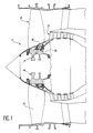
- the front of a turbojet engine has been represented in FIG. 1, and the fan 1 is recognized in particular at the inlet of the gas flow stream 2, in front of the low pressure compressor 3.
- the fan 1 is essentially composed of a rotor disc 4, fan blades 5, the feet of which are inserted into pinouts of the disc 4 and intermediate platforms 6, bolted to flanges 7 of the disc 4 and which maintain the blades 5 at their angular position.
- the intermediate platforms 6 form, like the hooves of the denarius patent cited, a crown delimiting the gas flow stream 2.
- damping arrangements 8 which extend radially between the platforms 6 and the rotor disc 4, and tangentially between the neighboring blades 5.
- a damping arrangement 8 is located between each pair of blades 5.
- a shock absorber arrangement 8 comprises a receptacle 9 provided with two end flanks 10 and 11 joined by groups of bolts 12 and 13 respectively to flanges 7 for fixing platforms 6 and to a flange 14 for joining the disc 4 and a casing 15 for the low pressure compressor rotor 3.
- the sides 11 and 12 are joined by an outer wall 16 which, as can be seen in FIG. 3, is bent and concave at the exterior, so that its internal face 17 (oriented towards the disc 4) is inclined radially outwards on both sides, in the direction of the lateral faces 18 of the blades 5, or more precisely of the lateral faces of their stilt immediately adjacent to the blade root 19 engaged in a pinout 20 of the disc 4.
- Housing 21 extends under the internal face 17 and between the sides 10 and 11. They are each occupied by a counterweight 22 which has a radially external face 23 rubbing against the face 17 and a tangentially external face 24 touching against the lateral face 18 of the stilts of the blades 5, at least during operation, when sufficient centrifugal forces are exerted to cause the weights 22 to protrude from the housings 21 by sliding obliquely along one side of the internal face 17. The rest of the time, the weights are surrounded by the receptacle 9, the blades 5 and the disc 4 and therefore remain held in their housing 21. Using a single receptacle 9 with two housings 21 and two weights 22 for two neighboring blades 5, and housings 21 communicating with each other through the bottom, a simpler and lighter arrangement is obtained.
- the damping arrangement 8 lends itself to a host of modifications by changing the mass or the shape of the counterweights 22, or the inclination of the internal face 17.
- the resumption of the centrifugal forces by the bolts 12 and 13 which unite other elements rotating in addition to the receptacles 9 to the rotor disc 4 avoids complicating the device and should equalize the forces on the flanges 7 and 14.
Abstract
Description
L'invention se rapporte à un agencement amortisseur monté entre des aubes d'un rotor.The invention relates to a damping arrangement mounted between blades of a rotor.
Elle a pour but d'amortir les vibrations de battement des aubes en direction tangentielle, c'est-à-dire dans la direction de rotation du disque sur lequel les aubes sont montés. Comme on le verra, on utilise pour cela des éléments mobiles entre les aubes et que les forces centrifuges repoussent, comme dans de nombreuses conceptions antérieures telles que celles qui sont illustrées dans les brevets français 2 352 159 ou, pour une réalisation plus compliquée, dans le brevet américain 4 182 590. Dans ces conceptions, un élément mobile presse simultanément sur les plates-formes de deux aubes voisines qui servent à canaliser les gaz en formant une surface extérieure lisse et continue au pied des aubes ; et ces plates-formes sont inclinées radialement vers l'extérieur depuis la pale de l'aube, c'est-à-dire que les deux plates-formes dessinent, en se rejoignant, une espèce de voûte au-dessus de l'élément mobile. Ce dernier est donc repoussé par les forces centrifuges au milieu de la voûte, à la jonction des deux plates-formes. Les battements des aubes en direction tangentielle font glisser les plates-formes sur les surfaces de l'élément, ce qui produit des frottements amortissant les vibrations.Its purpose is to dampen the vibrations of the blades beating in the tangential direction, that is to say in the direction of rotation of the disc on which the blades are mounted. As will be seen, mobile elements are used for this between the blades and which the centrifugal forces repel, as in many prior designs such as those which are illustrated in French patents 2 352 159 or, for a more complicated embodiment, in US Patent 4,182,590. In these designs, a movable element presses simultaneously on the platforms of two neighboring blades which serve to channel the gases by forming a smooth and continuous outer surface at the foot of the blades; and these platforms are inclined radially outwards from the blade of the blade, that is to say that the two platforms draw, by joining, a kind of arch above the element mobile. The latter is therefore pushed back by centrifugal forces in the middle of the vault, at the junction of the two platforms. The beating of the blades in a tangential direction causes the platforms to slide over the surfaces of the element, which produces friction dampening the vibrations.
Cette conception convenable est très employée pour des aubes mobiles de petite taille telles que celles d'un compresseur ou d'une turbine de moteur d'avion, mais elle est moins avantageuse pour les aubes beaucoup plus grandes qu'on rencontre en particulier sur la soufflante et qu'on désire alléger au maximum afin de réduire leur inertie. Une mesure très fréquence consiste alors à supprimer les plates-formes. Les éléments libres d'amortissement perdent alors les surfaces qui les retiennent.This suitable design is widely used for small movable blades such as those of an airplane engine compressor or turbine, but is less advantageous for the blades much larger than one meets in particular on the blower and which one wishes to lighten to the maximum in order to reduce their inertia. A very frequent measure then consists in removing the platforms. The free damping elements then lose the surfaces which hold them.
Une autre conception est présentée dans le brevet français 2 669 686. La veine d'écoulement des gaz n'est plus ici délimitée par des plates-formes d'aubes qui se rejoignent en voûte, mais par des pièces appelées sabots qui sont montées sur le disque de rotor et comprennent à l'extérieur une plate-forme qui comble l'intervalle entre deux pales d'aubes voisines. On trouve des éléments d'amortissement sous ces plates-formes, et ces éléments sont composés d'une paire de masselottes situées contre la face latérale d'une échasse d'aube respective et d'une entretoise en arceau constituant un ressort reliant les masselottes. Comme l'arceau touche à la plate-forme à son sommet, les forces centrifuges provoquent son ouverture en déplaçant radialement les masselottes, et cette ouverture contribue à écarter les masselottes d'un mouvement tangentiel et à les presser sur les échasses des aubes. Cependant, cette composante tangentielle des déplacements est faible, ce qui a pour conséquence que la force de pression entre les masselottes et les aubes est peu importante et que les vibrations de battement des aubes sont mal contenues.Another design is presented in French patent 2,669,686. The gas flow stream is no longer here delimited by platforms of blades which meet in a vault, but by pieces called shoes which are mounted on the rotor disc and comprise on the outside a platform which bridges the gap between two blades of neighboring blades. There are damping elements under these platforms, and these elements are composed of a pair of flyweights located against the lateral face of a respective blade stilt and of a hoop spacer constituting a spring connecting the flyweights . As the hoop touches the platform at its top, the centrifugal forces cause it to open by moving the weights radially, and this opening helps to move the weights apart in a tangential movement and to press them on the stilts of the blades. However, this tangential component of the displacements is small, which has the consequence that the pressure force between the weights and the blades is low and that the vibrations of beat of the blades are poorly contained.
L'invention repose sur une conception plus efficace pour amortir les vibrations de battement des aubes par des masselottes pressées contre leurs échasses par la force centrifuge ; les masselottes sont retenues plus avantageusement que par un ressort qui les réunit par paires.The invention is based on a more effective design for damping the vibrations of the vane flapping by weights pressed against their stilts by centrifugal force; the weights are retained more advantageously than by a spring which joins them in pairs.
Elles sont disposées chacune dans un logement d'un réceptacle solidaire du disque de rotor. Les logements s'ouvrent vers les faces latérales des aubes et sont délimités radialement vers l'extérieur par des portions de réceptacle qui présentent une inclinaison radiale vers l'extérieur en direction de l'ouverture des logements.They are each arranged in a housing of a receptacle secured to the rotor disc. The housings open towards the lateral faces of the blades and are delimited radially outwards by receptacle portions which have a radial inclination towards the outside in the direction of the opening of the housings.
Les masselottes glissent donc contre ces portions sous l'effet des forces centrifuges et sont repoussées hors des logements jusqu'à ce qu'elles touchent les aubes. Elles sont appliquées avec une force qui dépend de la force centrifuge mais aussi de l'inclinaison des portions de réceptacle et qui peut être assez élevée. Les vibrations des aubes, qui doivent vaincre cette force de pression et une force également importante de frottement entre la surface extérieure des masselottes et les portions extérieures des réceptacles, sont donc fortement amorties.The weights therefore slide against these portions under the effect of centrifugal forces and are pushed out of the housings until they touch the blades. They are applied with a force which depends on the centrifugal force but also on the inclination of the receptacle portions and which can be quite high. The vibrations of the blades, which must overcome this pressure force and an equally significant force of friction between the external surface of the weights and the external portions of the receptacles, are therefore strongly damped.
Ces détails et caractéristiques de l'invention, ainsi que d'autres, apparaîtront plus clairement au commentaire des dessins suivants qui illustrent une réalisation non limitative de l'invention :
- la figure 1 représente une situation d'emploi de l'agencement amortisseur de l'invention, et
- la figure 2 représente des coupes de cet agencement, respectivement selon la ligne II-II de la figure 3 et la ligne III-III de la figure 2.
- FIG. 1 represents a situation of use of the damping arrangement of the invention, and
- FIG. 2 represents sections of this arrangement, respectively along line II-II of FIG. 3 and line III-III of FIG. 2.
On a représenté l'avant d'un turboréacteur à la figure 1, et l'on reconnaît en particulier la soufflante 1 à l'entrée de la veine d'écoulement des gaz 2, devant le compresseur à basse pression 3. La soufflante 1 est composée essentiellement d'un disque 4 de rotor, d'aubes 5 de soufflante dont les pieds sont insérés dans des brochages du disque 4 et de plates-formes 6 intermédiaires, boulonnées à des brides 7 du disque 4 et qui maintiennent les aubes 5 à leur position angulaire. Les plates-formes intermédiaires 6 forment, comme les sabots du denrier brevet cité, une couronne délimitant la veine d'écoulement des gaz 2.The front of a turbojet engine has been represented in FIG. 1, and the fan 1 is recognized in particular at the inlet of the gas flow stream 2, in front of the low pressure compressor 3. The fan 1 is essentially composed of a
S'ajoutent à ces pièces les agencements amortisseurs 8 selon l'invention, qui s'étendent radialement entre les plates-formes 6 et le disque 4 de rotor, et tangentiellement entre les aubes 5 voisines. Un agencement amortisseur 8 se trouve entre chaque paire d'aubes 5.In addition to these parts, there are the damping arrangements 8 according to the invention, which extend radially between the
On se reporte maintenant aux figures 2 et 3. Un agencement amortisseur 8 comprend un réceptacle 9 muni de deux flancs extrêmes 10 et 11 réunis par des groupes de boulons 12 et 13 respectivement à des brides 7 de fixation des plates-formes 6 et à une bride 14 de jonction du disque 4 et une enveloppe 15 du rotor de compresseur à basse pression 3. Les flancs 11 et 12 sont réunis par une paroi extérieure 16 qui, comme on le voit bien à la figure 3, est recourbée et concave à l'extérieur, de sorte que sa face interne 17 (orientée vers le disque 4) est inclinée radialement vers l'extérieur des deux côtés, en direction des faces latérales 18 des aubes 5, ou plus précisément des faces latérales de leur échasse immédiatement adjacente au pied 19 d'aube engagé dans un brochage 20 du disque 4.Referring now to Figures 2 and 3. A shock absorber arrangement 8 comprises a
Des logements 21 s'étendent sous la face interne 17 et entre les flancs 10 et 11. Ils sont occupés chacun par une masselotte 22 qui présente une face radialement externe 23 frottant contre la face 17 et une face tangentiellement externe 24 touchant contre la face latérale 18 des échasses des aubes 5, du moins pendant le fonctionnement, quand des forces centrifuges suffisantes s'exercent pour faire saillir les masselottes 22 hors des logements 21 en glissant obliquement le long d'un côté de la face interne 17. Le reste du temps, les masselottes sont entourées par le réceptacle 9, les aubes 5 et le disque 4 et restent donc maintenues dans leur logement 21. En utilisant un seul réceptacle 9 à deux logements 21 et deux masselottes 22 pour deux aubes 5 voisines, et des logements 21 communiquant entre eux par le fond, un agencement plus simple et plus léger est obtenu.
L'agencement amortisseur 8 se prête à une foule de modifications en changeant la masse ou la forme des masselottes 22, ou l'inclinaison de la face interne 17. La reprise des efforts centrifuges par les boulons 12 et 13 qui unissent d'autres éléments tournants en sus des réceptacles 9 au disque 4 de rotor évite de compliquer le dispositif et devrait égaliser les efforts sur les brides 7 et 14.The damping arrangement 8 lends itself to a host of modifications by changing the mass or the shape of the
Claims (3)
Applications Claiming Priority (2)
| Application Number | Priority Date | Filing Date | Title |
|---|---|---|---|
| FR9511079A FR2739135B1 (en) | 1995-09-21 | 1995-09-21 | SHOCK ABSORBER ARRANGEMENT BETWEEN ROTOR BLADES |
| FR9511079 | 1995-09-21 |
Publications (2)
| Publication Number | Publication Date |
|---|---|
| EP0764766A1 true EP0764766A1 (en) | 1997-03-26 |
| EP0764766B1 EP0764766B1 (en) | 1999-11-03 |
Family
ID=9482787
Family Applications (1)
| Application Number | Title | Priority Date | Filing Date |
|---|---|---|---|
| EP96401991A Expired - Lifetime EP0764766B1 (en) | 1995-09-21 | 1996-09-19 | Device for suppressing vibrations mounted between rotor blades |
Country Status (5)
| Country | Link |
|---|---|
| US (1) | US5700133A (en) |
| EP (1) | EP0764766B1 (en) |
| CA (1) | CA2185854C (en) |
| DE (1) | DE69604998T2 (en) |
| FR (1) | FR2739135B1 (en) |
Cited By (2)
| Publication number | Priority date | Publication date | Assignee | Title |
|---|---|---|---|---|
| EP0918139A3 (en) * | 1997-11-25 | 2000-07-26 | ROLLS-ROYCE plc | Friction Damper |
| WO2014140449A1 (en) * | 2013-03-15 | 2014-09-18 | Snecma | Multiflow turbojet engine fan and turbojet engine fitted with such a fan |
Families Citing this family (4)
| Publication number | Priority date | Publication date | Assignee | Title |
|---|---|---|---|---|
| DE10022244A1 (en) * | 2000-05-08 | 2001-11-15 | Alstom Power Nv | Blade arrangement with damping elements |
| US6916154B2 (en) * | 2003-04-29 | 2005-07-12 | Pratt & Whitney Canada Corp. | Diametrically energized piston ring |
| US6991428B2 (en) * | 2003-06-12 | 2006-01-31 | Pratt & Whitney Canada Corp. | Fan blade platform feature for improved blade-off performance |
| US11193376B2 (en) * | 2020-02-10 | 2021-12-07 | Raytheon Technologies Corporation | Disk supported damper for a gas turbine engine |
Citations (3)
| Publication number | Priority date | Publication date | Assignee | Title |
|---|---|---|---|---|
| EP0089272A1 (en) * | 1982-03-12 | 1983-09-21 | Societe Nationale D'etude Et De Construction De Moteurs D'aviation, "S.N.E.C.M.A." | Turbine rotor comprising a damping device for the turbine blades |
| GB2138078A (en) * | 1983-04-14 | 1984-10-17 | Gen Electric | Dynamic response modification and stress reduction in blade root dovetail |
| US5205713A (en) * | 1991-04-29 | 1993-04-27 | General Electric Company | Fan blade damper |
Family Cites Families (7)
| Publication number | Priority date | Publication date | Assignee | Title |
|---|---|---|---|---|
| US4111603A (en) * | 1976-05-17 | 1978-09-05 | Westinghouse Electric Corp. | Ceramic rotor blade assembly for a gas turbine engine |
| FR2665726B1 (en) * | 1990-08-08 | 1993-07-02 | Snecma | TURBOMACHINE BLOWER WITH DYNAMIC CAM SHOCK ABSORBER. |
| FR2669686B1 (en) * | 1990-11-28 | 1994-09-02 | Snecma | BLOWER ROTOR WITH BLADES WITHOUT PLATFORMS AND SHOES RECONSTRUCTING THE VEIN PROFILE. |
| US5226784A (en) * | 1991-02-11 | 1993-07-13 | General Electric Company | Blade damper |
| US5156528A (en) * | 1991-04-19 | 1992-10-20 | General Electric Company | Vibration damping of gas turbine engine buckets |
| FR2716502B1 (en) * | 1994-02-23 | 1996-04-05 | Snecma | Sealing between vanes and intermediate platforms. |
| FR2726323B1 (en) * | 1994-10-26 | 1996-12-13 | Snecma | ASSEMBLY OF A ROTARY DISC AND BLADES, ESPECIALLY USED IN A TURBOMACHINE |
-
1995
- 1995-09-21 FR FR9511079A patent/FR2739135B1/en not_active Expired - Fee Related
-
1996
- 1996-09-17 US US08/714,978 patent/US5700133A/en not_active Expired - Lifetime
- 1996-09-18 CA CA002185854A patent/CA2185854C/en not_active Expired - Fee Related
- 1996-09-19 EP EP96401991A patent/EP0764766B1/en not_active Expired - Lifetime
- 1996-09-19 DE DE69604998T patent/DE69604998T2/en not_active Expired - Lifetime
Patent Citations (3)
| Publication number | Priority date | Publication date | Assignee | Title |
|---|---|---|---|---|
| EP0089272A1 (en) * | 1982-03-12 | 1983-09-21 | Societe Nationale D'etude Et De Construction De Moteurs D'aviation, "S.N.E.C.M.A." | Turbine rotor comprising a damping device for the turbine blades |
| GB2138078A (en) * | 1983-04-14 | 1984-10-17 | Gen Electric | Dynamic response modification and stress reduction in blade root dovetail |
| US5205713A (en) * | 1991-04-29 | 1993-04-27 | General Electric Company | Fan blade damper |
Cited By (5)
| Publication number | Priority date | Publication date | Assignee | Title |
|---|---|---|---|---|
| EP0918139A3 (en) * | 1997-11-25 | 2000-07-26 | ROLLS-ROYCE plc | Friction Damper |
| WO2014140449A1 (en) * | 2013-03-15 | 2014-09-18 | Snecma | Multiflow turbojet engine fan and turbojet engine fitted with such a fan |
| FR3003294A1 (en) * | 2013-03-15 | 2014-09-19 | Snecma | MULTI-FLOW TURBOMOTEUR BLOWER, AND TURBOMOTEUR EQUIPPED WITH SUCH BLOWER |
| GB2526475A (en) * | 2013-03-15 | 2015-11-25 | Snecma | Multiflow turbojet engine fan and turbojet engine fitted with such a fan |
| GB2526475B (en) * | 2013-03-15 | 2018-05-16 | Snecma | Fan for a multi-flow turboshaft engine, and turboshaft engine equipped with such a fan |
Also Published As
| Publication number | Publication date |
|---|---|
| US5700133A (en) | 1997-12-23 |
| DE69604998D1 (en) | 1999-12-09 |
| EP0764766B1 (en) | 1999-11-03 |
| DE69604998T2 (en) | 2000-05-18 |
| CA2185854A1 (en) | 1997-03-22 |
| CA2185854C (en) | 2007-12-04 |
| FR2739135B1 (en) | 1997-10-31 |
| FR2739135A1 (en) | 1997-03-28 |
Similar Documents
| Publication | Publication Date | Title |
|---|---|---|
| EP0488874A1 (en) | Fan rotor with blades without platforms and fillers reconstructing the streamline profile | |
| US5791877A (en) | Damping disposition for rotor vanes | |
| EP0062558A1 (en) | Stage of a gas turbine jet engine with air cooling means for the turbine rotor disc | |
| EP0208639B1 (en) | Device for suppressing vibrations in a tennis racket | |
| FR2629135A1 (en) | THRUST INVERTER FOR DOUBLE FLOW REACTOR | |
| EP0089272A1 (en) | Turbine rotor comprising a damping device for the turbine blades | |
| FR2585069A1 (en) | DEVICE FOR LIMITING THE ANGULAR DEBATMENT OF AUBES MOUNTED ON A TURBOMACHINE ROTOR DISK | |
| FR2670856A1 (en) | OSCILLATION DAMPING DEVICE. | |
| FR2915510A1 (en) | SHOCK ABSORBER FOR TURBOMACHINE BLADES | |
| EP0764766B1 (en) | Device for suppressing vibrations mounted between rotor blades | |
| FR2617538A1 (en) | FAIRING STRUCTURE OF TURBINE BLADES | |
| FR2472693A1 (en) | TWO-STAGE TORSIONAL VIBRATION DAMPER | |
| EP1007835B1 (en) | Backblast gas structure equipped with thrust reverser with two rear doors and planar exhaust area | |
| EP0415314B1 (en) | Condenser made of concrete for turbine with axial outlet and turbine with such a condenser | |
| FR3040369A1 (en) | AIRCRAFT ENGINE ASSEMBLY COMPRISING AN IMPROVED FRONT ENGINE ATTACHMENT | |
| FR2620502A1 (en) | TORSION DAMPER DEVICE | |
| WO2013107967A1 (en) | Angular downstream guide vane sector with vibration damping by means of a wedge for a turbine engine compressor | |
| EP1774249B1 (en) | Missile launcher | |
| FR2715968A1 (en) | Separating platform, fitting between blades on rotor | |
| EP0017567A1 (en) | Device for fixing blades to the rotor of the compressor of a turbojet plant | |
| FR2561307A1 (en) | Device for locking the vanes of blowers | |
| FR2655960A1 (en) | INSTALLATION FOR PROCESSING A BULK PRODUCT WITH A DEDUSTING DEVICE. | |
| EP0669451A1 (en) | Seal between the blades and the intermediate platforms | |
| WO2000001962A1 (en) | Hydrokinetic coupling apparatus for locking engagement | |
| FR2548732A1 (en) | DEVICE FOR DRIVING AN AUXILIARY APPARATUS ON AN INTERNAL COMBUSTION ENGINE |
Legal Events
| Date | Code | Title | Description |
|---|---|---|---|
| PUAI | Public reference made under article 153(3) epc to a published international application that has entered the european phase |
Free format text: ORIGINAL CODE: 0009012 |
|
| 17P | Request for examination filed |
Effective date: 19961007 |
|
| AK | Designated contracting states |
Kind code of ref document: A1 Designated state(s): DE FR GB |
|
| GRAG | Despatch of communication of intention to grant |
Free format text: ORIGINAL CODE: EPIDOS AGRA |
|
| 17Q | First examination report despatched |
Effective date: 19990315 |
|
| GRAG | Despatch of communication of intention to grant |
Free format text: ORIGINAL CODE: EPIDOS AGRA |
|
| GRAH | Despatch of communication of intention to grant a patent |
Free format text: ORIGINAL CODE: EPIDOS IGRA |
|
| GRAH | Despatch of communication of intention to grant a patent |
Free format text: ORIGINAL CODE: EPIDOS IGRA |
|
| GRAA | (expected) grant |
Free format text: ORIGINAL CODE: 0009210 |
|
| AK | Designated contracting states |
Kind code of ref document: B1 Designated state(s): DE FR GB |
|
| GBT | Gb: translation of ep patent filed (gb section 77(6)(a)/1977) |
Effective date: 19991116 |
|
| REF | Corresponds to: |
Ref document number: 69604998 Country of ref document: DE Date of ref document: 19991209 |
|
| PLBE | No opposition filed within time limit |
Free format text: ORIGINAL CODE: 0009261 |
|
| STAA | Information on the status of an ep patent application or granted ep patent |
Free format text: STATUS: NO OPPOSITION FILED WITHIN TIME LIMIT |
|
| 26N | No opposition filed | ||
| REG | Reference to a national code |
Ref country code: GB Ref legal event code: IF02 |
|
| REG | Reference to a national code |
Ref country code: FR Ref legal event code: TP Ref country code: FR Ref legal event code: CD |
|
| REG | Reference to a national code |
Ref country code: FR Ref legal event code: CD |
|
| REG | Reference to a national code |
Ref country code: GB Ref legal event code: 732E Free format text: REGISTERED BETWEEN 20120517 AND 20120523 |
|
| PGFP | Annual fee paid to national office [announced via postgrant information from national office to epo] |
Ref country code: DE Payment date: 20140822 Year of fee payment: 19 |
|
| PGFP | Annual fee paid to national office [announced via postgrant information from national office to epo] |
Ref country code: GB Payment date: 20140822 Year of fee payment: 19 |
|
| REG | Reference to a national code |
Ref country code: FR Ref legal event code: PLFP Year of fee payment: 20 |
|
| PGFP | Annual fee paid to national office [announced via postgrant information from national office to epo] |
Ref country code: FR Payment date: 20150909 Year of fee payment: 20 |
|
| REG | Reference to a national code |
Ref country code: DE Ref legal event code: R119 Ref document number: 69604998 Country of ref document: DE |
|
| GBPC | Gb: european patent ceased through non-payment of renewal fee |
Effective date: 20150919 |
|
| PG25 | Lapsed in a contracting state [announced via postgrant information from national office to epo] |
Ref country code: DE Free format text: LAPSE BECAUSE OF NON-PAYMENT OF DUE FEES Effective date: 20160401 Ref country code: GB Free format text: LAPSE BECAUSE OF NON-PAYMENT OF DUE FEES Effective date: 20150919 |