EP0764760B1 - Cutting insert for rotary drag bit - Google Patents
Cutting insert for rotary drag bit Download PDFInfo
- Publication number
- EP0764760B1 EP0764760B1 EP96306759A EP96306759A EP0764760B1 EP 0764760 B1 EP0764760 B1 EP 0764760B1 EP 96306759 A EP96306759 A EP 96306759A EP 96306759 A EP96306759 A EP 96306759A EP 0764760 B1 EP0764760 B1 EP 0764760B1
- Authority
- EP
- European Patent Office
- Prior art keywords
- substrate
- element according
- preform element
- recesses
- recess
- Prior art date
- Legal status (The legal status is an assumption and is not a legal conclusion. Google has not performed a legal analysis and makes no representation as to the accuracy of the status listed.)
- Expired - Lifetime
Links
- 238000005520 cutting process Methods 0.000 title description 22
- 239000000758 substrate Substances 0.000 claims description 110
- 239000000463 material Substances 0.000 claims description 31
- 230000002093 peripheral effect Effects 0.000 claims description 30
- 229910003460 diamond Inorganic materials 0.000 description 22
- 239000010432 diamond Substances 0.000 description 22
- 238000000034 method Methods 0.000 description 6
- 239000002245 particle Substances 0.000 description 6
- UONOETXJSWQNOL-UHFFFAOYSA-N tungsten carbide Chemical compound [W+]#[C-] UONOETXJSWQNOL-UHFFFAOYSA-N 0.000 description 6
- 238000004519 manufacturing process Methods 0.000 description 4
- 230000008569 process Effects 0.000 description 4
- 230000015572 biosynthetic process Effects 0.000 description 3
- 230000000694 effects Effects 0.000 description 3
- 239000007787 solid Substances 0.000 description 3
- 229910052582 BN Inorganic materials 0.000 description 2
- PZNSFCLAULLKQX-UHFFFAOYSA-N Boron nitride Chemical compound N#B PZNSFCLAULLKQX-UHFFFAOYSA-N 0.000 description 2
- OKTJSMMVPCPJKN-UHFFFAOYSA-N Carbon Chemical compound [C] OKTJSMMVPCPJKN-UHFFFAOYSA-N 0.000 description 2
- 229910000831 Steel Inorganic materials 0.000 description 2
- 229910052799 carbon Inorganic materials 0.000 description 2
- 230000032798 delamination Effects 0.000 description 2
- 238000004901 spalling Methods 0.000 description 2
- 239000010959 steel Substances 0.000 description 2
- 230000003313 weakening effect Effects 0.000 description 2
- 230000000712 assembly Effects 0.000 description 1
- 238000000429 assembly Methods 0.000 description 1
- 238000010276 construction Methods 0.000 description 1
- 238000005553 drilling Methods 0.000 description 1
- 239000012530 fluid Substances 0.000 description 1
- 230000007246 mechanism Effects 0.000 description 1
- 229910052751 metal Inorganic materials 0.000 description 1
- 239000002184 metal Substances 0.000 description 1
- 238000004663 powder metallurgy Methods 0.000 description 1
- 230000009467 reduction Effects 0.000 description 1
- 230000003014 reinforcing effect Effects 0.000 description 1
- 230000003252 repetitive effect Effects 0.000 description 1
- 238000000926 separation method Methods 0.000 description 1
- 238000007493 shaping process Methods 0.000 description 1
- 230000007704 transition Effects 0.000 description 1
Images
Classifications
-
- E—FIXED CONSTRUCTIONS
- E21—EARTH OR ROCK DRILLING; MINING
- E21B—EARTH OR ROCK DRILLING; OBTAINING OIL, GAS, WATER, SOLUBLE OR MELTABLE MATERIALS OR A SLURRY OF MINERALS FROM WELLS
- E21B10/00—Drill bits
- E21B10/46—Drill bits characterised by wear resisting parts, e.g. diamond inserts
- E21B10/56—Button-type inserts
- E21B10/567—Button-type inserts with preformed cutting elements mounted on a distinct support, e.g. polycrystalline inserts
- E21B10/573—Button-type inserts with preformed cutting elements mounted on a distinct support, e.g. polycrystalline inserts characterised by support details, e.g. the substrate construction or the interface between the substrate and the cutting element
- E21B10/5735—Interface between the substrate and the cutting element
-
- Y—GENERAL TAGGING OF NEW TECHNOLOGICAL DEVELOPMENTS; GENERAL TAGGING OF CROSS-SECTIONAL TECHNOLOGIES SPANNING OVER SEVERAL SECTIONS OF THE IPC; TECHNICAL SUBJECTS COVERED BY FORMER USPC CROSS-REFERENCE ART COLLECTIONS [XRACs] AND DIGESTS
- Y10—TECHNICAL SUBJECTS COVERED BY FORMER USPC
- Y10T—TECHNICAL SUBJECTS COVERED BY FORMER US CLASSIFICATION
- Y10T428/00—Stock material or miscellaneous articles
- Y10T428/24—Structurally defined web or sheet [e.g., overall dimension, etc.]
- Y10T428/24273—Structurally defined web or sheet [e.g., overall dimension, etc.] including aperture
- Y10T428/24281—Struck out portion type
- Y10T428/24289—Embedded or interlocked
-
- Y—GENERAL TAGGING OF NEW TECHNOLOGICAL DEVELOPMENTS; GENERAL TAGGING OF CROSS-SECTIONAL TECHNOLOGIES SPANNING OVER SEVERAL SECTIONS OF THE IPC; TECHNICAL SUBJECTS COVERED BY FORMER USPC CROSS-REFERENCE ART COLLECTIONS [XRACs] AND DIGESTS
- Y10—TECHNICAL SUBJECTS COVERED BY FORMER USPC
- Y10T—TECHNICAL SUBJECTS COVERED BY FORMER US CLASSIFICATION
- Y10T428/00—Stock material or miscellaneous articles
- Y10T428/24—Structurally defined web or sheet [e.g., overall dimension, etc.]
- Y10T428/24273—Structurally defined web or sheet [e.g., overall dimension, etc.] including aperture
- Y10T428/24322—Composite web or sheet
-
- Y—GENERAL TAGGING OF NEW TECHNOLOGICAL DEVELOPMENTS; GENERAL TAGGING OF CROSS-SECTIONAL TECHNOLOGIES SPANNING OVER SEVERAL SECTIONS OF THE IPC; TECHNICAL SUBJECTS COVERED BY FORMER USPC CROSS-REFERENCE ART COLLECTIONS [XRACs] AND DIGESTS
- Y10—TECHNICAL SUBJECTS COVERED BY FORMER USPC
- Y10T—TECHNICAL SUBJECTS COVERED BY FORMER US CLASSIFICATION
- Y10T428/00—Stock material or miscellaneous articles
- Y10T428/24—Structurally defined web or sheet [e.g., overall dimension, etc.]
- Y10T428/24479—Structurally defined web or sheet [e.g., overall dimension, etc.] including variation in thickness
- Y10T428/24521—Structurally defined web or sheet [e.g., overall dimension, etc.] including variation in thickness with component conforming to contour of nonplanar surface
-
- Y—GENERAL TAGGING OF NEW TECHNOLOGICAL DEVELOPMENTS; GENERAL TAGGING OF CROSS-SECTIONAL TECHNOLOGIES SPANNING OVER SEVERAL SECTIONS OF THE IPC; TECHNICAL SUBJECTS COVERED BY FORMER USPC CROSS-REFERENCE ART COLLECTIONS [XRACs] AND DIGESTS
- Y10—TECHNICAL SUBJECTS COVERED BY FORMER USPC
- Y10T—TECHNICAL SUBJECTS COVERED BY FORMER US CLASSIFICATION
- Y10T428/00—Stock material or miscellaneous articles
- Y10T428/24—Structurally defined web or sheet [e.g., overall dimension, etc.]
- Y10T428/24479—Structurally defined web or sheet [e.g., overall dimension, etc.] including variation in thickness
- Y10T428/24612—Composite web or sheet
-
- Y—GENERAL TAGGING OF NEW TECHNOLOGICAL DEVELOPMENTS; GENERAL TAGGING OF CROSS-SECTIONAL TECHNOLOGIES SPANNING OVER SEVERAL SECTIONS OF THE IPC; TECHNICAL SUBJECTS COVERED BY FORMER USPC CROSS-REFERENCE ART COLLECTIONS [XRACs] AND DIGESTS
- Y10—TECHNICAL SUBJECTS COVERED BY FORMER USPC
- Y10T—TECHNICAL SUBJECTS COVERED BY FORMER US CLASSIFICATION
- Y10T428/00—Stock material or miscellaneous articles
- Y10T428/24—Structurally defined web or sheet [e.g., overall dimension, etc.]
- Y10T428/24777—Edge feature
-
- Y—GENERAL TAGGING OF NEW TECHNOLOGICAL DEVELOPMENTS; GENERAL TAGGING OF CROSS-SECTIONAL TECHNOLOGIES SPANNING OVER SEVERAL SECTIONS OF THE IPC; TECHNICAL SUBJECTS COVERED BY FORMER USPC CROSS-REFERENCE ART COLLECTIONS [XRACs] AND DIGESTS
- Y10—TECHNICAL SUBJECTS COVERED BY FORMER USPC
- Y10T—TECHNICAL SUBJECTS COVERED BY FORMER US CLASSIFICATION
- Y10T428/00—Stock material or miscellaneous articles
- Y10T428/24—Structurally defined web or sheet [e.g., overall dimension, etc.]
- Y10T428/24942—Structurally defined web or sheet [e.g., overall dimension, etc.] including components having same physical characteristic in differing degree
Definitions
- the invention relates to elements faced with superhard material, and particularly to preform cutting elements comprising a facing table of superhard material having a front face, a peripheral surface, and a rear surface bonded to a substrate of material which is less hard than the superhard material.
- Preform elements of this kind are often used as cutting elements on rotary drag-type drill bits, and the present invention will be particularly described in relation to such use.
- the invention is not restricted to cutting elements for this particular use, and may relate to preform cutting elements for other purposes.
- elements faced with superhard material, of the kind referred to may also be employed in workpiece-shaping tools.
- Preform elements used as cutting elements in rotary drill bits usually have a facing table of polycrystalline diamond, although other superhard materials are available, such as cubic boron nitride and amorphous diamond-like carbon (ADLC).
- the substrate of less hard material is often formed from cemented tungsten carbide, and the facing table and substrate are bonded together during formation of the element in a high pressure, high temperature forming press. This forming process is well known and will not be described in detail.
- Each preform cutting element may be mounted on a carrier in the form of a generally cylindrical stud or post received in a socket in the body of the drill bit.
- the carrier is often formed from cemented tungsten carbide, the surface of the substrate being brazed to a surface on the carrier, for example by a process known as "LS bonding".
- the substrate itself may be of sufficient thickness as to provide, in effect, a cylindrical stud which is sufficiently long to be directly received in a socket in the bit body, without being brazed to a carrier.
- the bit body itself may be machined from metal, usually steel, or may be moulded using a powder metallurgy process.
- Such cutting elements are subjected to extremes of temperature during formation and mounting on the bit body, and are also subjected to high temperatures and heavy loads when the drill is in use down a borehole. It is found that as a result of such conditions spalling and delamination of the superhard facing table can occur, that is to say the separation and loss of the diamond or other superhard material over the cutting surface of the table.
- the interface between the superhard table and the substrate has usually been flat and planar.
- attempts have been made to improve the bond between the superhard facing table and the substrate by configuring the rear face of the facing table and the front face of the substrate so as to provide a degree of mechanical interlocking between them.
- the projections on the rear surface of the facing table require to project into the substrate to a considerable depth in order to provide an adequate locking function.
- the thickness of the substrate may be less than 3mm, and if the projections on the facing table are extended into the substrate to provide adequate interlocking between the facing table and substrate they may have the undesirable effect of weakening the structure of the substrate.
- This difficulty might, of course, be overcome by increasing the thickness of the substrate, but not only may thicker preforms be more difficult and costly to manufacture, but difficulties are also likely to arise due to existing manufacturing processes and designs of drill bit already being geared to preforms of the standard thickness.
- the present invention sets out to provide a design of preform element where the configuration of the projections on the rear surface of the facing table is such that they provide good interlocking between the facing table and substrate with comparatively small depth of the projections to the rear of the facing table.
- Preform elements of the kind to which the present invention relates are usually manufactured by first pre-forming a shaped solid substrate from suitable material, such as tungsten carbide, and then applying to one surface of the substrate a layer of diamond or other superhard particles.
- the superhard layer then automatically conforms to the shape of the substrate surface, the particles filling any recesses which have been pre-formed in that surface.
- the substrate and superhard layer are bonded together in the high pressure, high temperature forming press, the diamond particles bond together and to the substrate, and the rear surface of the superhard facing table becomes integrally formed with projections of superhard material which extend into the recesses in the substrate.
- certain characteristics of the finished preform element may depend on the shape and configuration of these superhard projections.
- the projections are usually, in practice, moulded according to the shape of the pre-formed substrate, it is convenient to define a desired configuration of superhard projections in terms of the shape of the substrate which is required to produce them, and the present invention will therefore be defined in such terms.
- a preform element including a facing table of superhard material having a front face, a peripheral surface, and a rear surface bonded to the front surface of a substrate which is less hard than the superhard material, the front surface of the substrate being formed around its periphery with a plurality of spaced recesses into which extend projections of superhard material integrally formed on the rear surface of the facing table, each recess having an outer edge which lies adjacent the periphery of the substrate, and the maximum length of each recess, along a radius of the substrate, being no greater than twice the maximum width of the recess in the peripheral direction.
- the superhard projections which fill the recesses also lie adjacent the periphery. This therefore provides the desirable additional strength to the facing table around its periphery and has a similar effect to the provision of a continuous peripheral ring as in the prior art arrangements.
- the reinforcing projections are spaced apart around the periphery of the facing table, the material of the substrate extends laterally between the spaced projections and this, together with the shape and size of the projections, provides a good mechanical interlock.
- the depth of the projections need be no more than the depth of the peripheral ring in the prior art arrangements.
- the projections unlike the continuous peripheral ring, also provide a mechanical interlock between the facing table and substrate it may no longer be necessary, in order to provide an adequate interlock, to form the rear surface of the facing table with projections which extend to a greater depth into the substrate.
- the present arrangement can provide increased peripheral strength plus mechanical interlocking in a depth of the projections which may be no greater than the depth of the peripheral ring of the prior art. This therefore avoids any possible weakening of the substrate which may result from the deeper projections of the prior art, and also avoids the manufacturing problems which would result from use of a thicker substrate, as mentioned above.
- each recess may form part of the outer periphery of the substrate.
- the recesses according to the invention are non-elongate, and preferably the maximum length of each recess is no greater than 1.5 times its maximum width in the peripheral direction. More preferably the maximum length of each recess is less than its maximum width in the peripheral direction.
- each recess may be curved, for example it may be part-circular or substantially semi-circular.
- the maximum length of the recess will be substantially half its width at the periphery.
- Each recess may have a bottom surface which is substantially flat and substantially parallel to the front face of the facing table.
- the recesses may all be of similar maximum depth, and the maximum depth of each recess may be similar to the thickness of the rest of the facing table.
- the maximum thickness of the facing table, including the projections which extend into said recesses in the substrate is less than half the overall thickness of the preform element.
- the recesses are preferably substantially equally spaced around the periphery of the substrate, and they may be the only recesses formed on the front surface of the substrate.
- the front surface of the substrate may have a central region and an outer peripheral region which is generally inclined away from the front face of the facing table as it extends outwardly, said recesses being formed in the inclined outer peripheral region of the substrate.
- each recess may increase in depth as it extends inwardly towards the central region of the substrate.
- each recess may be of substantially zero depth at its outer extremity.
- the inner extremity of each recess may lie adjacent the central region of the substrate.
- the central region of the front surface of the substrate may be substantially flat and parallel to the front face of the superhard facing table.
- the central region and/or the outer peripheral region of the front surface of the substrate may also be formed with a plurality of spaced subsidiary recesses into which extend protrusions of superhard material integrally formed on the rear surface of the facing table.
- the bottom surfaces of the first said recesses may also be formed with a plurality of spaced subsidiary recesses into which extend protrusions of superhard material integrally formed on the rear surface of the facing table.
- at least some of the subsidiary recesses intersect the outer periphery of the substrate, so that the protrusion of superhard material extending into the recess is partly exposed at the outer periphery of the preform element.
- the subsidiary recesses may be circular in cross-section.
- the depth of the subsidiary recesses may vary irregularly or randomly across the surface of the substrate.
- the subsidiary recesses may be arranged in a regular pattern across the surface of the substrate or may be spaced irregularly or randomly apart across the substrate.
- the element may be circular in configuration and of substantially constant thickness.
- Figures 1 and 2 show a typical full bore drag bit of a kind to which cutting elements of the present invention are applicable.
- the bit body 10 is machined from steel and has a shank formed with an externally threaded tapered pin 11 at one end for connection to the drill string.
- the operative end face 12 of the bit body is formed with a number of blades 13 radiating from the central area of the bit, and the blades carry cutter assemblies 14 spaced apart along the length thereof.
- the bit has a gauge section including kickers 16 which contact the walls of the borehole to stabilise the bit in the borehole.
- a central passage (not shown) in the bit and shank delivers drilling fluid through nozzles 17 in the end face 12 in known manner.
- Each cutter assembly 14 comprises a preform cutting element 18 mounted on a carrier 19 in the form of a post which is located in a socket in the bit body.
- Each preform cutting element is in the form of a circular tablet comprising a facing table 20 of superhard material, usually polycrystalline diamond, bonded to a substrate 21 which is normally of cemented tungsten carbide.
- the rear surface of the substrate is bonded, for example by LS bonding, to a suitably orientated surface on the post 19.
- the front facing table 20 of polycrystalline diamond is bonded in a high pressure, high temperature press to the tungsten carbide substrate 21.
- the process for making such preform elements is well known and will not be described in detail.
- polycrystalline diamond and tungsten carbide are the most common materials used for such preforms, other suitable materials may also be used.
- other suitable superhard materials for the facing table are cubic boron nitride and amorphous diamond-like carbon (ADLC).
- Figure 4 shows the front surface 22 of the substrate 21 with the facing table 20 removed to show the configuration of the front surface of the substrate.
- the front surface 22 of the substrate is formed around its periphery with eight peripherally spaced recesses 23 into which extend corresponding projections 24 on the underside of the facing table.
- Each recess has an outer edge 25, which forms part of the periphery of the substrate 21, and a curved semi-circular inner edge surface 26.
- the maximum length of each recess 23 along a radius of the facing table is less than the width of the recess in the peripheral direction.
- each recess is substantially flat and is parallel to the front surface 28 of the facing table.
- the depth of each recess is approximately equal to the thickness of the facing table, and it will be seen from Figure 3 that the combined thickness of the projections 24 and facing table 20 is less than half the overall thickness of the preform element as a whole.
- the diamond projections 24 which fill the recesses 23 extend around a major part of the outer periphery of the facing table 20, they provide additional strength to that outer periphery in similar manner to the continuous peripheral rings employed in the aforementioned prior art.
- the material of the substrate 21 extends outwardly between adjacent projections 23, into the regions indicated at 29 in Figure 4, and thus provide a good mechanical interlock between the facing table and substrate in addition to the added peripheral strength.
- This mechanical interlock is thus provided within the depth of the equivalent peripheral ring and does not require projections extending beyond the depth of the peripheral ring, as in many of the prior art arrangements. Consequently, the overall depth of the facing table and projections is minimised, and does not therefore lead to reduction in strength of the substrate.
- the projections 24 on the facing table 20 thus act in a different manner from the elongate radial and non-radial ribs shown in some prior art arrangements.
- the fact that the inner edge surfaces of the projections 24 are curved avoids stress concentrations within the substrate from which cracks may be initiated.
- Figure 5 shown an alternative arrangement which is similar to the arrangement of Figures 3 and 4 except that in this case the recesses 30 are smaller and there are provided twelve such recesses equally spaced around the periphery of the substrate.
- the invention includes arrangements where the recesses are non-equally spaced. Also, although in the preferred arrangement the bottom surfaces of the recesses are flat and parallel to the facing table, other shapes and orientations of the bottom surfaces are possible.
- the recesses may be of varying depths, around the periphery of the facing table, so that the corresponding projections on the facing table project into the substrate to different depths.
- Figure 7 shows the front surface of the substrate 31 with the polycrystalline diamond facing table 32 removed to show the configuration of the front surface of the substrate.
- the substrate 31 is again generally in the form of a circular tablet.
- the upper surface of the substrate, which provides the interface with the diamond facing table 32 comprises a flat circular central region 33 surrounded by an outer annular peripheral region 34 which is part-conical in form so that it is inclined away from the front surface 35 of the facing table as it extends outwardly.
- the outer peripheral region 34 is formed with eight part-circular recesses 36 which are spaced equally apart around the periphery of the substrate.
- the outer edge 37 of each recess 36 is of zero depth and forms part of the peripheral edge of the substrate.
- the inner curved edge of each recess is tangential to the circular central region 33.
- the bottom surface 38 of each recess 36 is parallel to the front face 35 of the facing table 32, as best seen in Figure 6, so that the recess increases in depth as it extends inwardly.
- each main recess 36 Three subsidiary recesses are formed in the bottom of each main recess 36. These comprise a recess 39 which is completely circular, and two recesses 40 which are semi-circular and intercept the outer periphery 41 of the substrate 31. Similar recesses 42 and 43 are also provided in the sloping surface 34 of the substrate between each adjacent pair of main recesses 36.
- Similar circular subsidiary recesses 44 are also formed in an array over the central region 33 ofthe upper surface of the substrate.
- the subsidiary recesses 39, 40, 42, 43 and 44 may be all of substantially the same depth or they may vary in depth in different locations over the surface of the substrate. For example, they may vary irregularly and randomly in depth across the surface of the substrate.
- the numbers, arrangement and shapes of the main recesses 36 and subsidiary recesses are by way of example only, and these recesses may differ in number, shape and arrangement from those shown in the drawing.
- a solid substrate is first formed in the configuration of Figures 4, 5 or 6, or any other configuration in accordance with the invention.
- the pre-formed substrate is then placed in a high pressure, high temperature press in contact with a layer of diamond particles which fill all the recesses as well as providing a continuous layer across the face of the substrate.
- a transition layer of material of intermediate characteristics may be located between the diamond particles and the substrate, in known manner.
- the assembly is then subjected to very high pressure and temperature in the press so that the diamond particles become bonded together, with diamond-to-diamond bonding, and also become bonded to the substrate to form the finished element as shown in Figures 3 and 6. Accordingly, all of the recesses of the substrate become completely filled with solid protrusions of diamond material which are integral with the facing table 20 or 32 and serve to lock the facing table to the substrate. Since the main recesses 23 and 36 are located at the periphery of the substrate, the diamond material which fills the recesses is exposed at the periphery of the element.
- the substrate which is placed in the press with the diamond layer may be of a diameter which is larger than that required for the finished element.
- the recesses which are closest to the periphery of the substrate such as the recesses 23, 30, 36, 40 and 43 may initially be complete circular recesses.
- the grinding removing part of the diamond-filled outer recesses so as to expose the diamond at the outer periphery of the element, as shown in Figures 3 and 6.
Landscapes
- Engineering & Computer Science (AREA)
- Life Sciences & Earth Sciences (AREA)
- Mining & Mineral Resources (AREA)
- Geology (AREA)
- Mechanical Engineering (AREA)
- Physics & Mathematics (AREA)
- Environmental & Geological Engineering (AREA)
- Fluid Mechanics (AREA)
- Chemical & Material Sciences (AREA)
- Crystallography & Structural Chemistry (AREA)
- General Life Sciences & Earth Sciences (AREA)
- Geochemistry & Mineralogy (AREA)
- Drilling Tools (AREA)
- Polishing Bodies And Polishing Tools (AREA)
Description
- The invention relates to elements faced with superhard material, and particularly to preform cutting elements comprising a facing table of superhard material having a front face, a peripheral surface, and a rear surface bonded to a substrate of material which is less hard than the superhard material.
- Preform elements of this kind are often used as cutting elements on rotary drag-type drill bits, and the present invention will be particularly described in relation to such use. However, the invention is not restricted to cutting elements for this particular use, and may relate to preform cutting elements for other purposes. For example, elements faced with superhard material, of the kind referred to, may also be employed in workpiece-shaping tools.
- Preform elements used as cutting elements in rotary drill bits usually have a facing table of polycrystalline diamond, although other superhard materials are available, such as cubic boron nitride and amorphous diamond-like carbon (ADLC). The substrate of less hard material is often formed from cemented tungsten carbide, and the facing table and substrate are bonded together during formation of the element in a high pressure, high temperature forming press. This forming process is well known and will not be described in detail.
- Each preform cutting element may be mounted on a carrier in the form of a generally cylindrical stud or post received in a socket in the body of the drill bit. The carrier is often formed from cemented tungsten carbide, the surface of the substrate being brazed to a surface on the carrier, for example by a process known as "LS bonding". Alternatively, the substrate itself may be of sufficient thickness as to provide, in effect, a cylindrical stud which is sufficiently long to be directly received in a socket in the bit body, without being brazed to a carrier. The bit body itself may be machined from metal, usually steel, or may be moulded using a powder metallurgy process.
- Such cutting elements are subjected to extremes of temperature during formation and mounting on the bit body, and are also subjected to high temperatures and heavy loads when the drill is in use down a borehole. It is found that as a result of such conditions spalling and delamination of the superhard facing table can occur, that is to say the separation and loss of the diamond or other superhard material over the cutting surface of the table.
- This may also occur in preform elements used for other purposes, and particularly where the elements are subjected to repetitive percussive loads, as in tappets and cam mechanisms.
- Commonly, in preform elements of the above type, the interface between the superhard table and the substrate has usually been flat and planar. However, particularly in cutting elements for drill bits, attempts have been made to improve the bond between the superhard facing table and the substrate by configuring the rear face of the facing table and the front face of the substrate so as to provide a degree of mechanical interlocking between them.
- It is also desirable, in preform elements of the above type, to provide increased thickness of the superhard facing table at its periphery to provide additional strength in that region which, in a cutting element for a rotary drill bit, provides the cutting edge of the element. Normally this has been achieved by forming a continuous peripheral ring of greater thickness and constant depth around the outer periphery of the rear surface of the facing table. In known arrangements it is often necessary or desirable for the projections on the rear surface of the facing table to be of greater depth than the peripheral ring, in order to provide adequate mechanical interlocking with the substrate.
- Various configurations of the interface between the superhard facing table and substrate in a preform element are described in British Patent Applications Nos. 2283773 (which represents the closest prior art as described in the preamble of claim 1), 9512173.7, 9512174.5, 9512177.8 and 9512175.2.
- While some of these existing designs can provide advantages, it may sometimes be found that the projections on the rear surface of the facing table require to project into the substrate to a considerable depth in order to provide an adequate locking function. For example, in some types of preform element the thickness of the substrate may be less than 3mm, and if the projections on the facing table are extended into the substrate to provide adequate interlocking between the facing table and substrate they may have the undesirable effect of weakening the structure of the substrate. This difficulty might, of course, be overcome by increasing the thickness of the substrate, but not only may thicker preforms be more difficult and costly to manufacture, but difficulties are also likely to arise due to existing manufacturing processes and designs of drill bit already being geared to preforms of the standard thickness.
- The present invention sets out to provide a design of preform element where the configuration of the projections on the rear surface of the facing table is such that they provide good interlocking between the facing table and substrate with comparatively small depth of the projections to the rear of the facing table.
- Preform elements of the kind to which the present invention relates are usually manufactured by first pre-forming a shaped solid substrate from suitable material, such as tungsten carbide, and then applying to one surface of the substrate a layer of diamond or other superhard particles. The superhard layer then automatically conforms to the shape of the substrate surface, the particles filling any recesses which have been pre-formed in that surface. When the substrate and superhard layer are bonded together in the high pressure, high temperature forming press, the diamond particles bond together and to the substrate, and the rear surface of the superhard facing table becomes integrally formed with projections of superhard material which extend into the recesses in the substrate.
- As previously explained, certain characteristics of the finished preform element may depend on the shape and configuration of these superhard projections. However, since the projections are usually, in practice, moulded according to the shape of the pre-formed substrate, it is convenient to define a desired configuration of superhard projections in terms of the shape of the substrate which is required to produce them, and the present invention will therefore be defined in such terms.
- According to the invention there is provided a preform element including a facing table of superhard material having a front face, a peripheral surface, and a rear surface bonded to the front surface of a substrate which is less hard than the superhard material, the front surface of the substrate being formed around its periphery with a plurality of spaced recesses into which extend projections of superhard material integrally formed on the rear surface of the facing table, each recess having an outer edge which lies adjacent the periphery of the substrate, and the maximum length of each recess, along a radius of the substrate, being no greater than twice the maximum width of the recess in the peripheral direction..
- In this arrangement according to the invention, since the outer edges of the recesses in the substrate lie adjacent the periphery of the facing table, the superhard projections which fill the recesses also lie adjacent the periphery. This therefore provides the desirable additional strength to the facing table around its periphery and has a similar effect to the provision of a continuous peripheral ring as in the prior art arrangements. However, since the reinforcing projections are spaced apart around the periphery of the facing table, the material of the substrate extends laterally between the spaced projections and this, together with the shape and size of the projections, provides a good mechanical interlock. The depth of the projections need be no more than the depth of the peripheral ring in the prior art arrangements. However, since the projections, unlike the continuous peripheral ring, also provide a mechanical interlock between the facing table and substrate it may no longer be necessary, in order to provide an adequate interlock, to form the rear surface of the facing table with projections which extend to a greater depth into the substrate.
- Thus the present arrangement can provide increased peripheral strength plus mechanical interlocking in a depth of the projections which may be no greater than the depth of the peripheral ring of the prior art. This therefore avoids any possible weakening of the substrate which may result from the deeper projections of the prior art, and also avoids the manufacturing problems which would result from use of a thicker substrate, as mentioned above.
- The outer edge of each recess may form part of the outer periphery of the substrate.
- The recesses according to the invention are non-elongate, and preferably the maximum length of each recess is no greater than 1.5 times its maximum width in the peripheral direction. More preferably the maximum length of each recess is less than its maximum width in the peripheral direction.
- Said inner edge of each recess, or the major part thereof, may be curved, for example it may be part-circular or substantially semi-circular. In the case where the whole of the inner edge of the recess is semi-circular the maximum length of the recess will be substantially half its width at the periphery.
- Each recess may have a bottom surface which is substantially flat and substantially parallel to the front face of the facing table.
- The recesses may all be of similar maximum depth, and the maximum depth of each recess may be similar to the thickness of the rest of the facing table. Preferably the maximum thickness of the facing table, including the projections which extend into said recesses in the substrate, is less than half the overall thickness of the preform element.
- The recesses are preferably substantially equally spaced around the periphery of the substrate, and they may be the only recesses formed on the front surface of the substrate.
- In any of the above arrangements the front surface of the substrate may have a central region and an outer peripheral region which is generally inclined away from the front face of the facing table as it extends outwardly, said recesses being formed in the inclined outer peripheral region of the substrate.
- In this case each recess may increase in depth as it extends inwardly towards the central region of the substrate. For example, each recess may be of substantially zero depth at its outer extremity. The inner extremity of each recess may lie adjacent the central region of the substrate.
- The central region of the front surface of the substrate may be substantially flat and parallel to the front face of the superhard facing table.
- The central region and/or the outer peripheral region of the front surface of the substrate may also be formed with a plurality of spaced subsidiary recesses into which extend protrusions of superhard material integrally formed on the rear surface of the facing table. The bottom surfaces of the first said recesses may also be formed with a plurality of spaced subsidiary recesses into which extend protrusions of superhard material integrally formed on the rear surface of the facing table. Preferably, at least some of the subsidiary recesses intersect the outer periphery of the substrate, so that the protrusion of superhard material extending into the recess is partly exposed at the outer periphery of the preform element.
- The subsidiary recesses may be circular in cross-section. The depth of the subsidiary recesses may vary irregularly or randomly across the surface of the substrate.
- The subsidiary recesses may be arranged in a regular pattern across the surface of the substrate or may be spaced irregularly or randomly apart across the substrate.
- In any of the arrangements according to the invention the element may be circular in configuration and of substantially constant thickness.
- The following is a more detailed description of embodiments of the invention, reference being made to the accompanying drawings in which:
- Figure 1 is a side elevation of a typical drag-type drill bit in which preform elements according to the present invention may be used as cutting elements,
- Figure 2 is an end elevation of the drill bit shown in Figure 1,
- Figure 3 is a cross-section, on an enlarged scale, of a preform cutting element in accordance with the invention,
- Figure 4 is a plan view of the substrate of the cutting element of Figure 3, the superhard facing table which would normally be bonded to the substrate having been removed to show the configuration of the upper face of the substrate,
- Figure 5 is a similar view to Figure 4 of an alternative embodiment.
- Figure 6 is a cross-section on an enlarged scale of another form of preform cutting element in accordance with the invention; and
- Figure 7 is a diagrammatic perspective view of the substrate of the cutting element of Figure 6, the superhard facing table having been removed to show the recesses in the upper surface of the substrate.
-
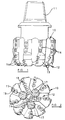
- Figures 1 and 2 show a typical full bore drag bit of a kind to which cutting elements of the present invention are applicable. The
bit body 10 is machined from steel and has a shank formed with an externally threaded tapered pin 11 at one end for connection to the drill string. The operative end face 12 of the bit body is formed with a number ofblades 13 radiating from the central area of the bit, and the blades carrycutter assemblies 14 spaced apart along the length thereof. The bit has a gauge section including kickers 16 which contact the walls of the borehole to stabilise the bit in the borehole. A central passage (not shown) in the bit and shank delivers drilling fluid throughnozzles 17 in theend face 12 in known manner. - Each
cutter assembly 14 comprises apreform cutting element 18 mounted on a carrier 19 in the form of a post which is located in a socket in the bit body. Each preform cutting element is in the form of a circular tablet comprising a facing table 20 of superhard material, usually polycrystalline diamond, bonded to asubstrate 21 which is normally of cemented tungsten carbide. The rear surface of the substrate is bonded, for example by LS bonding, to a suitably orientated surface on the post 19. - One form of preform cutting element for a rotary drill bit, in accordance with the invention, is shown in Figures 3 and 4.
- The front facing table 20 of polycrystalline diamond is bonded in a high pressure, high temperature press to the
tungsten carbide substrate 21. The process for making such preform elements is well known and will not be described in detail. Although polycrystalline diamond and tungsten carbide are the most common materials used for such preforms, other suitable materials may also be used. For example, other suitable superhard materials for the facing table are cubic boron nitride and amorphous diamond-like carbon (ADLC). - Figure 4 shows the
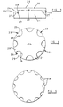
front surface 22 of thesubstrate 21 with the facing table 20 removed to show the configuration of the front surface of the substrate. As may be seen from Figure 4, thefront surface 22 of the substrate is formed around its periphery with eight peripherally spaced recesses 23 into which extend correspondingprojections 24 on the underside of the facing table. Each recess has anouter edge 25, which forms part of the periphery of thesubstrate 21, and a curved semi-circularinner edge surface 26. As may be seen from Figure 4, the maximum length of eachrecess 23 along a radius of the facing table is less than the width of the recess in the peripheral direction. - The
bottom surface 27 of each recess is substantially flat and is parallel to thefront surface 28 of the facing table. The depth of each recess is approximately equal to the thickness of the facing table, and it will be seen from Figure 3 that the combined thickness of theprojections 24 and facing table 20 is less than half the overall thickness of the preform element as a whole. - Since the
diamond projections 24 which fill therecesses 23 extend around a major part of the outer periphery of the facing table 20, they provide additional strength to that outer periphery in similar manner to the continuous peripheral rings employed in the aforementioned prior art. However, in the present case, unlike the prior art, the material of thesubstrate 21 extends outwardly betweenadjacent projections 23, into the regions indicated at 29 in Figure 4, and thus provide a good mechanical interlock between the facing table and substrate in addition to the added peripheral strength. This mechanical interlock is thus provided within the depth of the equivalent peripheral ring and does not require projections extending beyond the depth of the peripheral ring, as in many of the prior art arrangements. Consequently, the overall depth of the facing table and projections is minimised, and does not therefore lead to reduction in strength of the substrate. - The
projections 24 on the facing table 20 thus act in a different manner from the elongate radial and non-radial ribs shown in some prior art arrangements. The fact that the inner edge surfaces of theprojections 24 are curved avoids stress concentrations within the substrate from which cracks may be initiated. - Figure 5 shown an alternative arrangement which is similar to the arrangement of Figures 3 and 4 except that in this case the
recesses 30 are smaller and there are provided twelve such recesses equally spaced around the periphery of the substrate. - Although the
recesses - Another form of preform cutting element for a rotary drill bit, in accordance with the invention, is shown in Figures 6 and 7.
- Figure 7 shows the front surface of the
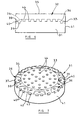
substrate 31 with the polycrystalline diamond facing table 32 removed to show the configuration of the front surface of the substrate. As may be seen from Figure 7, thesubstrate 31 is again generally in the form of a circular tablet. However, in this case the upper surface of the substrate, which provides the interface with the diamond facing table 32, comprises a flat circularcentral region 33 surrounded by an outer annularperipheral region 34 which is part-conical in form so that it is inclined away from thefront surface 35 of the facing table as it extends outwardly. - The outer
peripheral region 34 is formed with eight part-circular recesses 36 which are spaced equally apart around the periphery of the substrate. Theouter edge 37 of eachrecess 36 is of zero depth and forms part of the peripheral edge of the substrate. The inner curved edge of each recess is tangential to the circularcentral region 33. Thebottom surface 38 of eachrecess 36 is parallel to thefront face 35 of the facing table 32, as best seen in Figure 6, so that the recess increases in depth as it extends inwardly. - Three subsidiary recesses are formed in the bottom of each
main recess 36. These comprise arecess 39 which is completely circular, and tworecesses 40 which are semi-circular and intercept theouter periphery 41 of thesubstrate 31.Similar recesses surface 34 of the substrate between each adjacent pair ofmain recesses 36. - Similar circular subsidiary recesses 44 are also formed in an array over the
central region 33 ofthe upper surface of the substrate. - The subsidiary recesses 39, 40, 42, 43 and 44 may be all of substantially the same depth or they may vary in depth in different locations over the surface of the substrate. For example, they may vary irregularly and randomly in depth across the surface of the substrate. The numbers, arrangement and shapes of the
main recesses 36 and subsidiary recesses are by way of example only, and these recesses may differ in number, shape and arrangement from those shown in the drawing. - In one method of manufacture of the preform element, a solid substrate is first formed in the configuration of Figures 4, 5 or 6, or any other configuration in accordance with the invention. The pre-formed substrate is then placed in a high pressure, high temperature press in contact with a layer of diamond particles which fill all the recesses as well as providing a continuous layer across the face of the substrate. In some cases a transition layer of material of intermediate characteristics may be located between the diamond particles and the substrate, in known manner.
- The assembly is then subjected to very high pressure and temperature in the press so that the diamond particles become bonded together, with diamond-to-diamond bonding, and also become bonded to the substrate to form the finished element as shown in Figures 3 and 6. Accordingly, all of the recesses of the substrate become completely filled with solid protrusions of diamond material which are integral with the facing table 20 or 32 and serve to lock the facing table to the substrate. Since the
main recesses - In an alternative method of construction the substrate which is placed in the press with the diamond layer may be of a diameter which is larger than that required for the finished element. In this case the recesses which are closest to the periphery of the substrate, such as the
recesses - It is found that the arrangement shown in the drawings, as well as providing good mechanical interlock and bonding between the diamond table and substrate, also provides a diamond table which is highly resistant to impact loads, particularly at the periphery of the preform element, and is resistant to spalling and delamination of the diamond table from the substrate.
Claims (27)
- A preform element including a facing table (32) of superhard material having a front face (35), a peripheral surface, and a rear surface bonded to the front surface of a substrate (31) which is less hard than the superhard material, the front surface of the substrate being formed around its periphery with a plurality of spaced recesses (36) into which extend projections of superhard material integrally formed on the rear surface of the facing table (32), characterised in that each recess (36) has an outer edge (37) which lies adjacent the periphery of the substrate (31), and in that the maximum length of each recess, along a radius of the substrate, is no greater than twice the maximum width of the recess in the peripheral direction..
- A preform element according to Claim 1, wherein the outer edge (37) of each recess forms part of the outer periphery of the substrate (31).
- A preform element according to Claim 1 or Claim 2, wherein the maximum length of each recess (36), along a radius of the substrate, is no greater than 1.5 times its maximum width in the peripheral direction.
- A preform element according to Claim 1 or Claim 2, wherein the maximum length of each recess (36), along a radius of the substrate, is less than its maximum width in the peripheral direction.
- A preform element according to any of the preceding claims, wherein at least a major part of the inner edge of each recess (36) is curved.
- A preform element according to Claim 5, wherein said inner edge of each recess (36) is part-circular.
- A preform element according to Claim 5, wherein said inner edge of each recess (36) is semi-circular.
- A preform element according to any of the preceding claims, wherein each recess (36) has a bottom surface (38) which is substantially flat.
- A preform element according to Claim 8, wherein the bottom surface (38) of each recess (36) is substantially parallel to the front face (35) of the facing table.
- A preform element according to any of the preceding claims, wherein the recesses (36) are all of similar maximum depth.
- A preform element according to Claim 10, wherein the maximum depth of each recess (36) is similar to the thickness of the rest of the facing table (32).
- A preform element according to any of the preceding claims, wherein the maximum thickness of the facing table (32), including the projections which extend into said recesses (36) in the substrate, is less than half the overall thickness of the preform element.
- A preform element according to any of the preceding claims, wherein the recesses (36) are substantially equally spaced around the periphery of the substrate.
- A preform element according to any of the preceding claims, wherein said recesses (36) are the only recesses formed on the front surface of the substrate.
- A preform element according to any of the preceding claims, wherein the front surface ofthe substrate (31) has a central region (33) and an outer peripheral region (34) which is generally inclined away from the front face (35) of the facing table as it extends outwardly, said recesses (36) being formed in the inclined outer peripheral region (34) of the substrate.
- A preform element according to Claim 15, wherein each recess (36) increases in depth as it extends inwardly towards the central region (33) of the substrate.
- A preform element according to Claim 16, wherein each recess (36) is of substantially zero depth at its outer extremity (37).
- A preform element according to any of the preceding Claims 15 to 17, wherein the inner extremity of each recess (36) lies adjacent the central region (33) of the substrate.
- A preform element according to any of the preceding Claims 15 to 18, wherein the central region (33) of the front surface of the substrate is substantially flat and parallel to the front face (35) of the superhard facing table.
- A preform element according to any of the preceding Claims 15 to 19, wherein the central region (33) and/or the outer peripheral region (34) of the front surface of the substrate (31) is formed with a plurality of spaced subsidiary recesses (39,40,42,43,44) into which extend protrusions of superhard material integrally formed on the rear surface of the facing table (32).
- A preform element according to any of the preceding claims, wherein the bottom surfaces (38) of the first said recesses are formed with a plurality of spaced subsidiary recesses (39,40) into which extend protrusions of superhard material integrally formed on the rear surface of the facing table (32).
- A preform element according to Claim 20 or Claim 21, wherein at least some of the subsidiary recesses (40) intersect the outer periphery of the substrate, so that the protrusion of superhard material extending into the recess is partly exposed at the outer periphery of the preform element.
- A preform element according to any of Claims 20 to 22, wherein the subsidiary recesses (39,40,42,43,44) are circular in cross-section.
- A preform element according to any of Claims 20 to 23, wherein the depth of the subsidiary recesses (39,40,42,43,44) varies irregularly or randomly across the surface of the substrate.
- A preform element according to any of Claims 20 to 24, wherein the subsidiary recesses (39,40,42,43,44) are arranged in a regular pattern across the surface of the substrate.
- A preform element according to any of Claims 20 to 25, wherein the subsidiary recesses are spaced irregularly or randomly apart across the substrate.
- A preform element according to any of the preceding claims, wherein the element is circular in configuration and of substantially constant thickness.
Applications Claiming Priority (4)
| Application Number | Priority Date | Filing Date | Title |
|---|---|---|---|
| GBGB9519484.1A GB9519484D0 (en) | 1995-09-23 | 1995-09-23 | Improvements in or relating to elements faced with superhard material |
| GB9519484 | 1995-09-23 | ||
| GB9617520 | 1996-08-21 | ||
| GBGB9617520.3A GB9617520D0 (en) | 1996-08-21 | 1996-08-21 | Improvements in or relating to elements faced with superhard material |
Publications (3)
| Publication Number | Publication Date |
|---|---|
| EP0764760A2 EP0764760A2 (en) | 1997-03-26 |
| EP0764760A3 EP0764760A3 (en) | 1997-11-19 |
| EP0764760B1 true EP0764760B1 (en) | 2001-02-21 |
Family
ID=26307814
Family Applications (1)
| Application Number | Title | Priority Date | Filing Date |
|---|---|---|---|
| EP96306759A Expired - Lifetime EP0764760B1 (en) | 1995-09-23 | 1996-09-18 | Cutting insert for rotary drag bit |
Country Status (4)
| Country | Link |
|---|---|
| US (1) | US5888619A (en) |
| EP (1) | EP0764760B1 (en) |
| DE (1) | DE69611810T2 (en) |
| GB (1) | GB2305449B (en) |
Families Citing this family (21)
| Publication number | Priority date | Publication date | Assignee | Title |
|---|---|---|---|---|
| US5890552A (en) * | 1992-01-31 | 1999-04-06 | Baker Hughes Incorporated | Superabrasive-tipped inserts for earth-boring drill bits |
| GB2334269B (en) * | 1998-02-13 | 2002-04-17 | Camco Internat | Improvements in or relating to elements faced with superhard material |
| US6077591A (en) * | 1995-09-23 | 2000-06-20 | Camco International (Uk) Limited | Elements faced with superhard material |
| GB9717505D0 (en) * | 1997-08-20 | 1997-10-22 | Camco Int Uk Ltd | Improvements in or relating to cutting structures for rotary drill bits |
| US6082474A (en) * | 1997-07-26 | 2000-07-04 | Camco International Limited | Elements faced with superhard material |
| GB2327690B (en) * | 1997-07-26 | 2002-02-27 | Camco Internat | Improvements in or relating to the manufacture of elements faced with superhard material |
| DE69820349T2 (en) * | 1997-07-26 | 2004-10-28 | Camco International (Uk) Ltd., Stonehouse | Improvements to cutting elements with a surface made of super hard material |
| US6199645B1 (en) | 1998-02-13 | 2001-03-13 | Smith International, Inc. | Engineered enhanced inserts for rock drilling bits |
| GB9809690D0 (en) | 1998-05-08 | 1998-07-01 | Camco Int Uk Ltd | Improvements in elements faced with superhard material |
| JP2002196179A (en) * | 2000-10-17 | 2002-07-10 | Ngk Insulators Ltd | Fiber array, its manufacturing method, and optical device using the fiber array |
| US6488106B1 (en) | 2001-02-05 | 2002-12-03 | Varel International, Inc. | Superabrasive cutting element |
| US6513608B2 (en) | 2001-02-09 | 2003-02-04 | Smith International, Inc. | Cutting elements with interface having multiple abutting depressions |
| US6510910B2 (en) | 2001-02-09 | 2003-01-28 | Smith International, Inc. | Unplanar non-axisymmetric inserts |
| US6933509B1 (en) | 2001-09-11 | 2005-08-23 | Allasso Industries, Inc. | Apparatus and method using fractionated irradiation to harden metal |
| US6761851B1 (en) | 2001-09-11 | 2004-07-13 | Allasso Industries, Inc. | Apparatus and method for hardening metal by varying the engagement between irradiation and metal |
| US6750459B1 (en) | 2001-09-11 | 2004-06-15 | Allasso Industries, Inc. | Apparatus and method using irradiation to harden metal |
| US20060058085A1 (en) * | 2004-09-13 | 2006-03-16 | Pokertek, Inc. | Electronic player interaction area with player customer interaction features |
| GB2474180A (en) * | 2008-07-25 | 2011-04-06 | Smith International | PDC bit having split blades |
| US9138872B2 (en) | 2013-03-13 | 2015-09-22 | Diamond Innovations, Inc. | Polycrystalline diamond drill blanks with improved carbide interface geometries |
| GB201309798D0 (en) * | 2013-05-31 | 2013-07-17 | Element Six Abrasives Sa | Superhard constructions & methods of making same |
| CN113631307B (en) * | 2019-03-26 | 2024-04-26 | 三菱综合材料株式会社 | Base material for hard sintered body, and cutting tool |
Family Cites Families (6)
| Publication number | Priority date | Publication date | Assignee | Title |
|---|---|---|---|---|
| US5351772A (en) * | 1993-02-10 | 1994-10-04 | Baker Hughes, Incorporated | Polycrystalline diamond cutting element |
| US5486137A (en) * | 1993-07-21 | 1996-01-23 | General Electric Company | Abrasive tool insert |
| GB2308142B (en) * | 1993-11-10 | 1998-02-25 | Camco Drilling Group Ltd | Improvements in or relating to elements faced with superhard material |
| GB2283772B (en) * | 1993-11-10 | 1997-01-15 | Camco Drilling Group Ltd | Improvements in or relating to elements faced with superhard material |
| GB9412247D0 (en) * | 1994-06-18 | 1994-08-10 | Camco Drilling Group Ltd | Improvements in or relating to elements faced with superhard material |
| US5534329A (en) * | 1994-07-14 | 1996-07-09 | Bunimovich; Haim | Composite structure |
-
1996
- 1996-09-18 DE DE69611810T patent/DE69611810T2/en not_active Expired - Fee Related
- 1996-09-18 EP EP96306759A patent/EP0764760B1/en not_active Expired - Lifetime
- 1996-09-18 GB GB9619486A patent/GB2305449B/en not_active Expired - Lifetime
- 1996-09-18 US US08/716,586 patent/US5888619A/en not_active Expired - Lifetime
Also Published As
| Publication number | Publication date |
|---|---|
| GB9619486D0 (en) | 1996-10-30 |
| US5888619A (en) | 1999-03-30 |
| EP0764760A2 (en) | 1997-03-26 |
| GB2305449A (en) | 1997-04-09 |
| GB2305449B (en) | 1999-04-07 |
| DE69611810T2 (en) | 2001-08-23 |
| DE69611810D1 (en) | 2001-03-29 |
| EP0764760A3 (en) | 1997-11-19 |
Similar Documents
| Publication | Publication Date | Title |
|---|---|---|
| EP0764760B1 (en) | Cutting insert for rotary drag bit | |
| US5617928A (en) | Elements faced with superhard material | |
| EP0688937B1 (en) | Improvements in or relating to elements faced with superhard material | |
| EP0655549B1 (en) | Improvements in or relating to elements faced with superhard material | |
| US6739417B2 (en) | Superabrasive cutters and drill bits so equipped | |
| EP0733777B1 (en) | Cutting insert for rotary drag drill bit | |
| CA2151899C (en) | Tool component | |
| US6082474A (en) | Elements faced with superhard material | |
| EP0601840A1 (en) | Improvements in or relating to cutting elements for rotary drill bits | |
| EP0655548A1 (en) | Improvements in or relating to cutting elements for rotary drill bits | |
| US5788001A (en) | Elements faced with superhard material | |
| GB2327692A (en) | Preform element faced with superhard material | |
| US6077591A (en) | Elements faced with superhard material | |
| GB2308144A (en) | Improvements relating to elements faced with superhard material | |
| EP0738823B1 (en) | Improvements in or relating to elements faced with superhard material | |
| EP0893572B1 (en) | Improvements in or relating to elements faced with superhard material | |
| EP0936012A1 (en) | Elements faced with superhard material | |
| GB2331538A (en) | Preform elements faced with a superhard material |
Legal Events
| Date | Code | Title | Description |
|---|---|---|---|
| PUAI | Public reference made under article 153(3) epc to a published international application that has entered the european phase |
Free format text: ORIGINAL CODE: 0009012 |
|
| AK | Designated contracting states |
Kind code of ref document: A2 Designated state(s): BE DE FR IE |
|
| PUAL | Search report despatched |
Free format text: ORIGINAL CODE: 0009013 |
|
| AK | Designated contracting states |
Kind code of ref document: A3 Designated state(s): BE DE FR IE |
|
| 17P | Request for examination filed |
Effective date: 19980508 |
|
| GRAG | Despatch of communication of intention to grant |
Free format text: ORIGINAL CODE: EPIDOS AGRA |
|
| 17Q | First examination report despatched |
Effective date: 20000510 |
|
| GRAG | Despatch of communication of intention to grant |
Free format text: ORIGINAL CODE: EPIDOS AGRA |
|
| GRAH | Despatch of communication of intention to grant a patent |
Free format text: ORIGINAL CODE: EPIDOS IGRA |
|
| GRAH | Despatch of communication of intention to grant a patent |
Free format text: ORIGINAL CODE: EPIDOS IGRA |
|
| GRAA | (expected) grant |
Free format text: ORIGINAL CODE: 0009210 |
|
| AK | Designated contracting states |
Kind code of ref document: B1 Designated state(s): BE DE FR IE |
|
| REG | Reference to a national code |
Ref country code: IE Ref legal event code: FG4D |
|
| REF | Corresponds to: |
Ref document number: 69611810 Country of ref document: DE Date of ref document: 20010329 |
|
| ET | Fr: translation filed | ||
| PLBE | No opposition filed within time limit |
Free format text: ORIGINAL CODE: 0009261 |
|
| STAA | Information on the status of an ep patent application or granted ep patent |
Free format text: STATUS: NO OPPOSITION FILED WITHIN TIME LIMIT |
|
| 26N | No opposition filed | ||
| PGFP | Annual fee paid to national office [announced via postgrant information from national office to epo] |
Ref country code: FR Payment date: 20050823 Year of fee payment: 10 |
|
| PGFP | Annual fee paid to national office [announced via postgrant information from national office to epo] |
Ref country code: IE Payment date: 20050913 Year of fee payment: 10 |
|
| PGFP | Annual fee paid to national office [announced via postgrant information from national office to epo] |
Ref country code: DE Payment date: 20050915 Year of fee payment: 10 |
|
| PGFP | Annual fee paid to national office [announced via postgrant information from national office to epo] |
Ref country code: BE Payment date: 20051123 Year of fee payment: 10 |
|
| PG25 | Lapsed in a contracting state [announced via postgrant information from national office to epo] |
Ref country code: IE Free format text: LAPSE BECAUSE OF NON-PAYMENT OF DUE FEES Effective date: 20060918 |
|
| PG25 | Lapsed in a contracting state [announced via postgrant information from national office to epo] |
Ref country code: BE Free format text: LAPSE BECAUSE OF NON-PAYMENT OF DUE FEES Effective date: 20060930 |
|
| PG25 | Lapsed in a contracting state [announced via postgrant information from national office to epo] |
Ref country code: DE Free format text: LAPSE BECAUSE OF NON-PAYMENT OF DUE FEES Effective date: 20070403 |
|
| REG | Reference to a national code |
Ref country code: IE Ref legal event code: MM4A |
|
| REG | Reference to a national code |
Ref country code: FR Ref legal event code: ST Effective date: 20070531 |
|
| BERE | Be: lapsed |
Owner name: *CAMCO DRILLING GROUP LTD Effective date: 20060930 |
|
| PG25 | Lapsed in a contracting state [announced via postgrant information from national office to epo] |
Ref country code: FR Free format text: LAPSE BECAUSE OF NON-PAYMENT OF DUE FEES Effective date: 20061002 |