EP0764377B1 - X.25 access to frame relay network - Google Patents
X.25 access to frame relay network Download PDFInfo
- Publication number
- EP0764377B1 EP0764377B1 EP95919947A EP95919947A EP0764377B1 EP 0764377 B1 EP0764377 B1 EP 0764377B1 EP 95919947 A EP95919947 A EP 95919947A EP 95919947 A EP95919947 A EP 95919947A EP 0764377 B1 EP0764377 B1 EP 0764377B1
- Authority
- EP
- European Patent Office
- Prior art keywords
- packet
- frame relay
- packets
- routing
- network
- Prior art date
- Legal status (The legal status is an assumption and is not a legal conclusion. Google has not performed a legal analysis and makes no representation as to the accuracy of the status listed.)
- Expired - Lifetime
Links
- 238000000034 method Methods 0.000 claims description 16
- 206010047289 Ventricular extrasystoles Diseases 0.000 claims description 5
- 230000005540 biological transmission Effects 0.000 claims description 3
- 238000012545 processing Methods 0.000 claims description 2
- 238000005538 encapsulation Methods 0.000 description 8
- 239000000872 buffer Substances 0.000 description 6
- 238000004891 communication Methods 0.000 description 5
- 238000013519 translation Methods 0.000 description 4
- 238000010200 validation analysis Methods 0.000 description 4
- 241000245032 Trillium Species 0.000 description 3
- 238000005516 engineering process Methods 0.000 description 3
- ODKSFYDXXFIFQN-BYPYZUCNSA-N L-arginine Chemical compound OC(=O)[C@@H](N)CCCN=C(N)N ODKSFYDXXFIFQN-BYPYZUCNSA-N 0.000 description 2
- 230000008901 benefit Effects 0.000 description 2
- 238000010586 diagram Methods 0.000 description 2
- 230000006870 function Effects 0.000 description 2
- 238000013507 mapping Methods 0.000 description 2
- 230000008569 process Effects 0.000 description 2
- 238000011084 recovery Methods 0.000 description 2
- 238000012546 transfer Methods 0.000 description 2
- 102100023817 26S proteasome complex subunit SEM1 Human genes 0.000 description 1
- 101000684297 Homo sapiens 26S proteasome complex subunit SEM1 Proteins 0.000 description 1
- 101000873438 Homo sapiens Putative protein SEM1, isoform 2 Proteins 0.000 description 1
- 230000009471 action Effects 0.000 description 1
- 230000006978 adaptation Effects 0.000 description 1
- 230000008859 change Effects 0.000 description 1
- 230000000295 complement effect Effects 0.000 description 1
- 230000003247 decreasing effect Effects 0.000 description 1
- 238000013461 design Methods 0.000 description 1
- 101150069022 dss-1 gene Proteins 0.000 description 1
- 230000000694 effects Effects 0.000 description 1
- 239000000284 extract Substances 0.000 description 1
- 230000010354 integration Effects 0.000 description 1
- 230000007246 mechanism Effects 0.000 description 1
- 238000005192 partition Methods 0.000 description 1
- 230000004044 response Effects 0.000 description 1
Images




Classifications
-
- H—ELECTRICITY
- H04—ELECTRIC COMMUNICATION TECHNIQUE
- H04L—TRANSMISSION OF DIGITAL INFORMATION, e.g. TELEGRAPHIC COMMUNICATION
- H04L12/00—Data switching networks
- H04L12/66—Arrangements for connecting between networks having differing types of switching systems, e.g. gateways
Definitions
- This invention relates to a PVC backbone for packet switching networks capable of implementing CCITT X protocols, such as the X25 protocol.
- the primary protocol to be implemented by the X.25 service is the X.25 CCITT standard, 1988 version.
- Other related protocols are X.75, X.32, and the "triple X" PAD (Packet Assembler-Dissembler) (X.3, X.28, X.29).
- X.25 is an interface specification for statistically multiplexing several independent data streams onto common facilities. It uses a link layer based on HDLC frames, using LAPB between the DTE and the DCE.
- An object of this invention is to provide an improved network supporting X-series packet and call protocol.
- a first aspect of the present invention provides a packet switching network supporting X-series protocol access comprising a plurality of packet engines, each including routing software for X-series packets, and a plurality of trunks interconnecting said packet engines for transporting packets between said packet engines under the control of said routing software, said trunks serving as the backbone for the network, wherein the trunks comprise permanent virtual connections established over frame relay links between said packet engines.
- the invention also provides a node for use in a data transmission system, comprising a packet engine supporting X-series protocol access and including processing means providing support for HDLC and LAPB at the link level, and X-series packet and call-control protocol, characterized in that a frame relay packet transport system is used to transmit X-series packets between packet engines with no errors, no loss and in sequence, and a routing system identifies a permanent virtual connection between packet engines within specified time limits, and maintains connectivity in the event of failures, errors and congestion.
- the node includes a management system that provides the configuration data for the above system, and integrated management services, a system for reliably gathering accounting data from the nodes, and a system for validating Network User Identifiers
- the X-series protocol may be X.25 operating at speeds of 9.6K to T1/E1.
- Each node that supporting X.25 has one or more X.25 Packet Engines.
- This Packet Engine supports X.25 interfaces to users on either its own access ports, or through subrate interfaces.
- the X.25 Packet Engines connect to other X.25 packet engines through frame relay PVCs. These PVCs terminate on software processes within the Packet Engines. They act as trunks over which the X.25 data packets are multiplexed by the X.25 transport and routing software on the Packet Engine.
- This invention employs the frame relay protocol described in: ANSI T1.602, ANSI T1.606, ANSI T1S1/90-175, ANSI T1.617 - DSS 1, ANSI T1.618 - DSS1, CCITT Recommendation I.122, CCITT Recommendation Q.922, CCITT Recommendation Q.933.
- the X.25 protocol is described in CCITT Recommendation X.25.
- the invention still further provides a method of transferring X.25 LAPB packets between packet engines, each including routing software for the X-25 packets, characterized in that it comprises the steps of establishing a permanent virtual connection between the packet engines using frame relay protocol, encapsulating the X.25 LAPB packets into frame relay frames and attaching a DLCI identifier, transmitting the encapsulated frames between the packet engines over the permanent virtual connection under the control of said routing software, and stripping off the frame relay header from the received encapsulated frames to recover the LAPB packets.
- This invention overcomes the above difficulties experienced in conventional systems by using PVCs, for example frame relay PVC's, as the backbone trunks for a packet switching network.
- PVCs for example frame relay PVC's
- This allows the use of frame relay explicit congestion notification to individually flow control virtual circuits.
- a more robust and reliable backbone network is created.
- This robustness is further enhanced by the use of the frame relay Explicit Congestion Notification bits, the techniques of Q.922, and the procedures in this invention to flow control the individual virtual circuits.
- X.25 is the primary packet-switching protocol to be supported.
- the interface to the backbone is based on C language subroutine calls for virtual circuit setup, packet transfer and flow control, so any other packet oriented protocol (such as SNA) may be supported through this interface.
- SNA packet oriented protocol
- the memory required to handle the storage and buffer requirements is defined by the following formula.
- the formula is based on: (ports * LCNs * average packet size * average window size) + total software.
- a real-time clock is required to provide accurate start and end times in the accounting records if the software cannot provide timing accurate within 1 second.
- HDLC frame streams between the DTE (user) and the DCE (Packet Engine) must be multiplexed onto DS0s, for example, using DTUs, and subrate interfaces. This allows very effective backhaul from central offices direct to the packet engine.
- the X.25 protocol is implemented in layers of smaller subsystems.
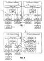
- the X.25 Packet Engine 1 provides X.25 DCE (Data Communications Equipment) functionality, allowing any X.25 DTE 2 (Data Terminal Equipment) to connect using the CCITT X.25 standard.
- X.25 DCE Data Communications Equipment
- X.25 DTE 2 Data Terminal Equipment
- the link level connection 3 uses the standard CCITT X.25 LAPB (Link Access Protocol Balanced) protocol as implemented by Trillium software.
- the X.25 Engine 1 receives packets from the DTE 2 encapsulated within HDLC frames as described in the X.25 standard.
- Requests to set up SVCs are sent in-band by using call request packets. They contain the requested address, an LCN (Logical channel number) to use for multiplexing subsequent data packets, and a variable length list of facilities (call-options) requested for the duration of the call.
- LCN Logical channel number
- Network management data is received from the network manager 4 ( Figure 2).
- the following table summarizes the activities of the network manager 4.
- ACTION DATA ITEMS CROSS-CHECKS 1.
- Configure network alter, delete
- Network name Herald Address format
- escape digits Default packet size and ranges
- Default window sizes and ranges (mod 8, mod 128) Segment size Accounting intervals
- DNIC None 2.
- Configure X.25 Engine (alter, delete, move, copy, schedule) Routing ID Hardware address
- Software modules and versions Configuration parameters 3600 node control data
- Assign Frame Relay trunks (alter, delete, move, copy, schedule) Endpoint addresses of X.25 Engines Frame Relay parameters Frame relay assignment parameters X.25 Engine assignments 4.
- Configure X.25 Port (alter, delete, move, copy, schedule) LCN ranges Routing I.D. Facilities Billing information X.25 Gateway information and address translation tables X.25 Engine definition Hardware addresses Memory engineering Processor engineering X.121 addresses 5. Assign X.121 address (delete, move, schedule) X.121 address X.25 port and LCN X.25 port assignment Network configuration X.121 address uniqueness 6. Assign CUG CUG directory, options X.121 addresses 7. Assign X.25 PVC (alter, delete, move, copy, schedule) PVC address, endpoint LCNs X.121 addresses X.25 port assignment LCNs 8. Configure NUI (alter, delete, schedule) NUI id, password, billing information None 9. Configure Hunt Group (alter, delete, schedule) HG Address Call distribution options X.121 addresses 9. Collect Accounting Call reference number Addresses Start time and duration segments transferred facilities requested 10. Monitor alarms Alarm type source severity time additional data 11. Define spooling site
- the routing system 5 receives routing and topology information from peer systems in other nodes.
- the X.25 Engine receives NUI (Network User Identifier) validation responses from the NUI database 6. This provides validation information for any NUI in the network. It must be accessible from any port in the network. It must also provide administration functions for password change, NUI cancellation, and indications of usage.
- NUI Network User Identifier
- At least 200 NUI/Passwords must be stored on the Packet Engine to provide a fast NUI validation by the X.25 transport layer.
- This table will become a local cache for the global NUI database system, but will initially be downloaded from a simple NUI managment function.
- the X.25 Engine 1 sends packets to the DTE 2 encapsulated within HDLC frames as described in the X.25 standard.
- Network alarms, status indicators and statistics are delivered to the network management system 4.
- the routing system 5 sends routing and topology information to peer systems in other nodes.
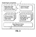
- the X.25 link layer, packet layer and transport layer software run on the Packet Engine ( Figure 3), as does the routing system and Frame Relay PVC trunks.
- the Packet Engine is based on a standard Frame Relay Engine with the additional of 16 Megabytes of memory and a real time clock and includes network address tables 20, X.25 access interfaces 21, Network management interfaces 22, packet routing system 23, and frame relay trunk interfaces 24.
- the X.25 DCE Data Link Layer 3 provides access via subroutines. It receives HDLC frames either directly from drivers handling the super-rate interfaces, or from the subrate feeder interface.
- the DCE Network Layer 11 is also a port of the Trillium X.25/X.75 DCE interface software to run on the Packet Engine.
- the X.25 Transport Layer 9 provides a packet-transport protocol for the X.25 DCE Network Layer, using the X.25 routing system and frame relay PVC trunks. It provides the following services:
- the X.25 Transport Layer 9 thus manages the connection between the X.25 DCE software and the X.25 routing system.
- the X.25 DCE software provides subroutine calls to deliver and receive packets from a network layer. It expects this layer to handle the transport of packets through the network.
- the X.25 Transport Layer 9 makes the best use of the features available from the routing and trunking system. It handles the translation of X.121 addresses to routing ids when it binds the ends of an SVC during call setup. It forwards packets to the X.25 routing system, buffer and time the packets for retransmission, and either retransmit on timeout or discard upon receipt of an acknowlegment. It receives packets from the X.25 routing system, acknowledge them, and forward them to the X.25 packet layer in the proper sequence and without duplicates.
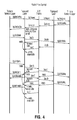
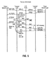
- the X.25 transport layer 9 must also provide flow control to the packet layer. Details of the packet flow control are shown in Figures 4 and 5. It makes use of the Explicit Congestion Notification bits from the frame relay protocol used by the trunking system to dynamically adjust the window sizes of any virtual circuit that may be experiencing congestion.
- a call request When a call request is sent through the Transport Layer, it will record the assigned or negotiated window size for the call, and assign that number of "credits" to the virtual circuit.
- the credit counter will be decremented for each packet received from the packet layer, and incremented for each acknowledgment received from the trunking system. If the credit counter ever reaches 0, then a flow control notification will be sent to the packet layer. When the credit counter eventually increases, the flow control notification will be cancelled.
- the reception of a packet with the BECN bit set indicate that that particular virtual circuit was following a route that was experiencing some form of congestion. Rather than immediately disrupt the network by trying to re-route or re-establish the call, an attempt will be made to temporarily throttle the data flowing on the virtual circuits over that route until the congestion is resolved. This is done by decreasing the current credit count to some fraction of the original window size, but never less than one. This will cause flow control notifications to be sent more frequently, reducing the throughput and hence congestion on that route. If the packets being received on that virtual circuit no longer have the BECN bits set, the credit count will be gradually increased back to the original window size.
- the packets may start arriving with clear BECN bits for two reasons: either the congestion has cleared up, or the routing system has re-routed the path over a different set of trunks. In both cases, it is valid to stop throttling the data.
- the techniques used for adjusting the credit counts are based on the window adjustment techniques and CCITT standard Q.922, Annex I.
- the network address tables 23 must provide a network-wide, consistent mapping of X.121 addresses to routing addresses that are understood by the packet routing system.
- the X.121 address can be as long as 19 BCD digits .
- the routing id's consist of two parts: the packet engine address, and the port address on the packet engine.
- One way to shorten the tables is to put only the information required at each node into its tables, and to partition the address assignments to each node. Outgoing packets only need to map the address as far as required to determine the destination node id. Each node keeps a full mapping of address to final hardware id for the ports directly on that node.
- Each node is assigned one or more address prefixes, analogous to an area code on the telephone network.
- the LSRouter (or generic frame router) can be used to exchange this information along with its routing table updates. This insures that the information is consistent and up to date throughout the network.
- the X.25 Packet Routing (LSRouter) 23 is an adaptation of the CPSS LSRouter. This system receives outgoing packets from the transport layer 9 and enqueues them for the X.25 trunk as indicated by the current routing tables. Packets for a local destination are put in the queue for that port address. Incoming packets are switched to the queue for the port address if the destination is on the node, or put into the queue for the next trunk hop if it is a transit packet. The packet routing system does not distinguish between data packets or call progress packets.
- packets queued by the routing system are transmitted using the frame relay protocol as described in ITU-T, Q.933 and ANSI t1.617. Packets received from the frame relay PVC are queued for the routing system, along with any explicit congestion information.
- the subrate feeder interface receives HDLC subrate data streams multiplexed on a DS-0 channel. It de-multiplexes and decapsulates the HDLC frames and deliver them to the link layer software.
- X.25 Gateways provide a connection to other X.25 networks. They offer the option of connecting either a DCE or DTE to a similar gateway configured as the complementary DTE or DCE on the other network.
- the X.75 gateways X.75 Gateways provide connections between X.25 networks using DNIC (Data Network Identifier Code) in the addresses. This is normally limited to public networks.
- the X.75 gateway (STE) connects to a similar X.75 gateway (STE) on the other network using LAPB and a form of X.25 that is similar to but more symmetric than the X.25 DTE-DCE protocol.
- the network routing system must recognize the DNIC in an address and route the call to a gateway to the network identified by the DNIC.
- This network may be connected directly to the gateway, or indirectly via a transit network, which adds complexity to the routing decisions.
- the X.25 Engine sends NUI validation requests to the NUI database as set out I.
- the design of the X.25 Engine is then based on five main objects as shown in Figure 3, namely an X.25 service encapsulator 21, an address translation database 20, a routing system controller 23, a network management interface 22, and a trunk interface 24.
- the packet engine comprises a packet object, which incorporates data and flow control packets, and queue objects, which operate on Packet objects. These comprise the The LAPB receive queue, the LAPB send queue, the FR trunk send queue, the FR trunk receive queue, the packet level retransmit queue, the call router serving queue, the packet router serving queue, and the free buffer queue (sorted by address to make it easy to recombine buffers).
- the X.25 Engine or packet engine supports up to 60 directly connected high speed X.25 interfaces.
- a Subrate Feeder Interface provides the appropriate connection for these devices.
- An encapsulation technique is used to transport the X.25 HDLC frames through the FRS and backplane to the X.25 Engine. This encapsulation technique is supported on the X.25 Engine, the FRS, and any other device that will be connected to the packet engine. It allows the LAPB protocol to run transparently between the X.25 device and the X.25 Engine.
- the X.25 devices use HDLC to send LAPB frames, not Frame Relay frames, to the FRS.
- the FRS encapsulates the LAPB frames into frame relay frames and attach a DLCI identifier.
- the current FRS routing software routes these frames onto the circuits to the X.25 Engine. Packets from the X.25 Engine have the frame relay header stripped off and only the LAPB frame will be sent on the link to the X.25 device.
- Each X.25 device is allocated a single DLCI to the X.25 Engine. This allows the X.25 software to correctly identify the LCN and X.25 device.
- the packet engine with X.25 software also terminates circuits from the FRS that carry X.25 packets encapsulated in frame relay frames.
- the feeder interface extracts the original X.25 packet and passes it on to the X.25 DCE software. Packets from the X.25 DCE software will be encapsulated and routed over the frame relay connection to devices on the FRS. Each device is identified either by the DLCI used to connect to it, or by addressing information contained within the encapsulation data.
- the routing system controller is based on a link-state routing system similar to OSPF. Other routing systems may be supported by implementing the appropriate routing objects. This allows integration with ATM backbone trunks.
- the network management interface 22 provides communications between the X.25 software objects and the 4602 network management system.
- the CPSS will still provide the basic communication path between the nodes and the 4602.
- the trunk interface 24 provides an interface to the frame relay system.
- Each trunk queue corresponds to a frame relay PVC.
- PVCs can be very quickly configured by the network management system and put into service by the X.25 system. This gives network operators a large operational benefit and cost saving. It becomes easier and faster to fine tune the engineering and utilization of the X.25 trunks.
- Frame relay features such as CIR and BECN can help provide a higher quality of service to the X.25 users.
- the protocol that runs between the trunk interface processes is based on LAPB. Protocol identification, routing information and the X.25 packets will be encapsulated in the information bytes of the LAPB frames.
- Future trunking systems can be based on newer ATM technology. Combined with the LWS system. This could allow the X.25 network to dynamically deploy and configure "trunks" as required by the network traffic.
- Packets being sent on a frame relay feeder interface and on the frame relay trunks need to be encapsulated within frame relay frames. This encapsulation must pass the user information and the X.25 packet information transparently.
- the routing information must be inserted at the sending node and examined by the routing system at transit and termination points.
- Standard encapsulation techniques provide mechanisms for integrating flow control between the frame relay and X.25 protocols. Encapsulation techniques are described in Q.922 (Annex A), and ANSI T! 617a (Annex F) and FRF.3 annex F, "Multiprotocol Encapsulation Implementation Agreement".
- the encapsulation techniques must notify LCNs multiplexed on the DLCI of congestion and recovery as indexed on the FECN and BECN bits, and transfer congestion information across trunk PVCs associated with each LCN.
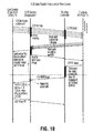
- FIGS 7 to 12 show various data flows in the packet switching network according to the invention.
- Figure 13 shows a detailed implementation of an X.25-frarme relay newtork.
- An advantage of the invention is that all the network management features and ability to provide virtual bandwidth offered by frame relay can be utilized in an X.25 service.
Landscapes
- Engineering & Computer Science (AREA)
- Computer Networks & Wireless Communication (AREA)
- Signal Processing (AREA)
- Data Exchanges In Wide-Area Networks (AREA)
Description
| ACTION | DATA ITEMS | CROSS-CHECKS | |
| 1. Configure network (alter, delete) | Network name, herald Address format, escape digits Default packet size and ranges Default window sizes and ranges (mod 8, mod 128) Segment size Accounting | None | |
| 2. Configure X.25 Engine (alter, delete, move, copy, schedule) | Routing ID Hardware address Software modules and versions Configuration parameters | 3600 | |
| 3. Assign Frame Relay trunks (alter, delete, move, copy, schedule) | Endpoint addresses of X.25 Engines Frame Relay parameters | Frame relay assignment parameters X.25 | |
| 4. Configure X.25 Port (alter, delete, move, copy, schedule) | LCN ranges Routing I.D. Facilities Billing information X.25 Gateway information and address translation tables | X.25 Engine definition Hardware addresses Memory engineering Processor engineering X.121 addresses | |
| 5. Assign X.121 address (delete, move, schedule) | X.121 address X.25 port and LCN | X.25 port assignment Network configuration X.121 address uniqueness | |
| 6. Assign CUG | CUG directory, options | X.121 addresses | |
| 7. Assign X.25 PVC (alter, delete, move, copy, schedule) | PVC address, endpoint LCNs | X.121 addresses X.25 port assignment LCNs | |
| 8. Configure NUI (alter, delete, schedule) | NUI id, password, | None | |
| 9. Configure Hunt Group (alter, delete, schedule) | HG Address Call distribution options | X.121 addresses | |
| 9. Collect Accounting | Call reference number Addresses Start time and duration segments transferred facilities requested | ||
| 10. Monitor alarms | Alarm type source severity time additional data | ||
| 11. Define spooling site |
- At call setup, translates the X.121 addresses in the address tables 12 in the call packet to internal routing ids, and binds the two ends of the virtual circuit
- buffers transmitted packets and starts a retransmission timer
- releases the buffer and stops the timer upon receipt of an acknowledgment
- retransmits the packet upon time-out
- acknowledges received packets, discard duplicates, and resequence any packets received out of order
- delivers packets to the Trillium network layer software in order
- flow controls packets from the Trillium network layer using congestion information received from the frame relay trunks, based on Q.922 Annex A and Frame Relay forum standards
- detects errors and recover appropriately - reset or clear the call only if absolutely necessary
- responds to queries from the network management system
- collects and forwards accounting data.
Packets for a local destination are put in the queue for that port address. Incoming packets are switched to the queue for the port address if the destination is on the node, or put into the queue for the next trunk hop if it is a transit packet. The packet routing system does not distinguish between data packets or call progress packets.
- use explicit address translation tables
- use subaddresses
- use the address extension facility from the X.25 DTE facilities
- use the user data field in the call request packet
- integrate the address assignment schemes across the two networks

Claims (7)
- A packet switching network supporting X-series protocol access comprising a plurality of packet engines (1), each including routing software (5) for X-series packets, and a plurality of trunks interconnecting said packet engines for transporting packets between said packet engines (1) under the control of said routing software (5), said trunks serving as the backbone for the network, characterized in that said trunks comprise permanent virtual connections (Frame Relay PVCs) established over frame relay links between said packet engines (1).
- A packet switching network as claimed in claim 1, characterized in that said frame relay PVCs are integrated into a routing system (5) that monitors the states of the PVCs and uses an OSPF-like procedure to calculate paths over the PVCs between the X-series packet engines.
- A packet switching network as claimed in claim 2, characterized in that frame relay explicit congestion notification (ECN) bits are used to provide flow control in the individual permanent virtual connections.
- A node for use in a data transmission system, comprising a packet engine (1) supporting X-series protocol access and including processing means (3) providing support for HDLC and LAPB at the link level, and X-series packet and call-control protocol, characterized in that a frame relay packet transport (Fig 13a) system is used to transmit X-series packets between packet engines (1) with no errors, no loss and in sequence, and a routing system (5) identifies a permanent virtual connection between packet engines within specified time limits, and maintains connectivity in the event of failures, errors and congestion.
- A node as claimed in claim 4, characterized in that means (1) are provided for encapsulating outgoing LAPB X.25 frames into frame relay frames and attaching a DLCI identifier for transmission over the identified permanent virtual connection.
- A method of transferring X.25 LAPB packets between packet engines, each including routing software for the X-25 packets, characterized in that it comprises the steps of establishing a permanent virtual connection between the packet engines using frame relay protocol, encapsulating the X.25 LAPB packets into frame relay frames and attaching a DLCI identifier, transmitting the encapsulated frames between the packet engines over the permanent virtual connection under the control of said routing software, and stripping off the frame relay header from the received encapsulated frames to recover the LAPB packets.
- A method as claimed in claim 6, characterized in that each packet engine is allocated a single DLCI.
Applications Claiming Priority (3)
| Application Number | Priority Date | Filing Date | Title |
|---|---|---|---|
| GB9411357 | 1994-06-07 | ||
| GB9411357A GB9411357D0 (en) | 1994-06-07 | 1994-06-07 | Data transmission system |
| PCT/CA1995/000329 WO1995034151A1 (en) | 1994-06-07 | 1995-06-07 | X.25 access to frame relay network |
Publications (2)
| Publication Number | Publication Date |
|---|---|
| EP0764377A1 EP0764377A1 (en) | 1997-03-26 |
| EP0764377B1 true EP0764377B1 (en) | 1999-12-15 |
Family
ID=10756305
Family Applications (1)
| Application Number | Title | Priority Date | Filing Date |
|---|---|---|---|
| EP95919947A Expired - Lifetime EP0764377B1 (en) | 1994-06-07 | 1995-06-07 | X.25 access to frame relay network |
Country Status (7)
| Country | Link |
|---|---|
| US (1) | US5917823A (en) |
| EP (1) | EP0764377B1 (en) |
| AU (1) | AU2558895A (en) |
| CA (1) | CA2192166A1 (en) |
| DE (1) | DE69513975T2 (en) |
| GB (1) | GB9411357D0 (en) |
| WO (1) | WO1995034151A1 (en) |
Families Citing this family (19)
| Publication number | Priority date | Publication date | Assignee | Title |
|---|---|---|---|---|
| US6463477B1 (en) * | 1996-09-27 | 2002-10-08 | Mci Communications Corporation | Detection of presence of multiprotocol encapsulation in a data packet |
| US6125119A (en) * | 1997-10-15 | 2000-09-26 | International Business Machines Corporation | Dynamic permanent virtual connection (DPVC) at user-to-network interfaces in frame relay networks |
| US6208650B1 (en) * | 1997-12-30 | 2001-03-27 | Paradyne Corporation | Circuit for performing high-speed, low latency frame relay switching with support for fragmentation and reassembly and channel multiplexing |
| US6363051B1 (en) * | 1998-06-30 | 2002-03-26 | At&T Corp. | Method and apparatus for achieving fast reconnection of permanent virtal channels in a frame relay network |
| US6879993B1 (en) * | 1999-02-25 | 2005-04-12 | Nortel Networks Limited | Apparatus and method for binding a connection-oriented client to a communication channel |
| US6766381B1 (en) | 1999-08-27 | 2004-07-20 | International Business Machines Corporation | VLSI network processor and methods |
| FR2798796B1 (en) * | 1999-09-17 | 2001-11-30 | Matra Nortel Communications | PACKET TRANSMISSION METHOD, INTERFACE DEVICES AND SWITCHING EQUIPMENT FOR IMPLEMENTING THE METHOD |
| US7006441B1 (en) | 1999-12-16 | 2006-02-28 | At&T Corp. | Link state network having weighted control message processing |
| US6665730B1 (en) | 1999-12-16 | 2003-12-16 | At&T Corp. | Method and apparatus for transaction routing in a connection-oriented packet network using a non-fault-tolerant directory server |
| DE10037746B4 (en) * | 2000-08-02 | 2004-09-02 | Siemens Ag | Realization concept of intelligent telecommunication networks for signaling performance features in ISDN |
| US6885634B1 (en) | 2001-01-24 | 2005-04-26 | At&T Corp. | Network protocol having staggered recovery |
| US7394764B2 (en) * | 2001-12-14 | 2008-07-01 | Sasken Communication Technologies Limited | Technique for improving transmission control protocol performance in lossy networks |
| US7965693B2 (en) * | 2002-05-28 | 2011-06-21 | Zte (Usa) Inc. | Interworking mechanism between wireless wide area network and wireless local area network |
| US7453837B2 (en) * | 2002-08-15 | 2008-11-18 | Zteit Usa, Inc. | Trunking system for CDMA wireless communication |
| US7474895B1 (en) | 2004-03-04 | 2009-01-06 | Zte (Usa) Inc. | Frequency reuse in wireless communication networks |
| CA2563696A1 (en) * | 2004-04-19 | 2005-10-27 | Zteit Usa, Inc. | Trunking and push-to-talk mechanisms for wcdma wireless communications |
| US7729303B2 (en) * | 2004-06-30 | 2010-06-01 | Zteit Usa, Inc. | Global open trunking system for CDMA wireless communication |
| US7859996B2 (en) * | 2004-10-29 | 2010-12-28 | Broadcom Corporation | Intelligent congestion feedback apparatus and method |
| US8687649B2 (en) | 2011-03-08 | 2014-04-01 | International Business Machines Corporation | Message forwarding toward a source end node in a converged network environment |
Family Cites Families (8)
| Publication number | Priority date | Publication date | Assignee | Title |
|---|---|---|---|---|
| US5251207A (en) * | 1992-03-10 | 1993-10-05 | International Business Machines Corporation | Combined terminal adapter for SMDS and frame relay high speed data services |
| US5734654A (en) * | 1993-08-05 | 1998-03-31 | Fujitsu Limited | Frame relay switching apparatus and router |
| US5600798A (en) * | 1993-10-26 | 1997-02-04 | International Business Machines Corporation | System and method for controlling LAN data flow control through a frame relay network by end point station transmitting notification to LAN stations based on congestion notification from the frame relay network |
| US5533017A (en) * | 1994-05-02 | 1996-07-02 | Advanced Micro Devices, Inc. | Line interface device for fast-packet switching network |
| US5521909A (en) * | 1994-07-22 | 1996-05-28 | Newbridge Networks Corporation | Frame relay management system |
| US5535199A (en) * | 1994-09-06 | 1996-07-09 | Sun Microsystems, Inc. | TCP/IP header compression X.25 networks |
| US5490140A (en) * | 1994-09-30 | 1996-02-06 | International Business Machines Corporation | System and method for providing ATM support for frame relay DTEs with a terminal adapter |
| US5490141A (en) * | 1994-09-30 | 1996-02-06 | International Business Machines Corporation | System and method for providing SVC service through an ATM network for frame relay DTEs with a terminal adapter |
-
1994
- 1994-06-07 GB GB9411357A patent/GB9411357D0/en active Pending
-
1995
- 1995-06-07 WO PCT/CA1995/000329 patent/WO1995034151A1/en not_active Ceased
- 1995-06-07 DE DE69513975T patent/DE69513975T2/en not_active Expired - Fee Related
- 1995-06-07 US US08/737,808 patent/US5917823A/en not_active Expired - Fee Related
- 1995-06-07 CA CA002192166A patent/CA2192166A1/en not_active Abandoned
- 1995-06-07 EP EP95919947A patent/EP0764377B1/en not_active Expired - Lifetime
- 1995-06-07 AU AU25588/95A patent/AU2558895A/en not_active Abandoned
Also Published As
| Publication number | Publication date |
|---|---|
| DE69513975D1 (en) | 2000-01-20 |
| EP0764377A1 (en) | 1997-03-26 |
| CA2192166A1 (en) | 1995-12-14 |
| AU2558895A (en) | 1996-01-04 |
| DE69513975T2 (en) | 2000-07-20 |
| US5917823A (en) | 1999-06-29 |
| GB9411357D0 (en) | 1994-07-27 |
| WO1995034151A1 (en) | 1995-12-14 |
Similar Documents
| Publication | Publication Date | Title |
|---|---|---|
| US5917823A (en) | X.25 access to frame relay network | |
| US8127029B1 (en) | Internet protocol based network architecture for cable television network access with switched fallback | |
| US6954463B1 (en) | Distributed packet processing architecture for network access servers | |
| McAuley | Protocol design for high speed networks | |
| US5453980A (en) | Communication network and computer network server and interface modules used therein | |
| US6412006B2 (en) | Method and apparatus for sending delay sensitive information assisted by packet switched networks | |
| US7616646B1 (en) | Intraserver tag-switched distributed packet processing for network access servers | |
| US6385204B1 (en) | Network architecture and call processing system | |
| US6781994B1 (en) | Distributing ATM cells to output ports based upon destination information using ATM switch core and IP forwarding | |
| US5548578A (en) | LAN-to-LAN communication method, and LAN-to-LAN connecting unit | |
| US20020010866A1 (en) | Method and apparatus for improving peer-to-peer bandwidth between remote networks by combining multiple connections which use arbitrary data paths | |
| KR20010072843A (en) | Apparatus and method for a remote access server | |
| US6717914B1 (en) | System for probing switched virtual circuits in a connection oriented network | |
| US6473430B2 (en) | Systems and methods for connecting frame relay devices via an ATM network using a frame relay proxy signaling agent | |
| US5999524A (en) | Dial access switching interface for frame relay | |
| JPH1168755A (en) | ATM network broadcast control system, network device and switching node device | |
| US6243380B1 (en) | Method and apparatus for mapping asynchronous ports to HDLC addresses | |
| US5724511A (en) | Remote maintenance control system | |
| JP2004505527A (en) | Communications system | |
| Doeringer et al. | Access architecture for a multiprotocol broadband backbone | |
| Muller | The Management Aspects of Frame Relay | |
| EP1118186A1 (en) | Network to network bandwidth on demand | |
| KR100204046B1 (en) | Parameter Setting Method of Broadband Capability Information Element Field in Public Network Asynchronous Transfer Mode Switching System | |
| Bohm | The DTM protocol: Design and Implementation | |
| KR0174675B1 (en) | Traffic control method of protocol converter |
Legal Events
| Date | Code | Title | Description |
|---|---|---|---|
| PUAI | Public reference made under article 153(3) epc to a published international application that has entered the european phase |
Free format text: ORIGINAL CODE: 0009012 |
|
| 17P | Request for examination filed |
Effective date: 19961227 |
|
| AK | Designated contracting states |
Kind code of ref document: A1 Designated state(s): DE FR GB |
|
| 17Q | First examination report despatched |
Effective date: 19980805 |
|
| GRAG | Despatch of communication of intention to grant |
Free format text: ORIGINAL CODE: EPIDOS AGRA |
|
| GRAG | Despatch of communication of intention to grant |
Free format text: ORIGINAL CODE: EPIDOS AGRA |
|
| GRAH | Despatch of communication of intention to grant a patent |
Free format text: ORIGINAL CODE: EPIDOS IGRA |
|
| GRAH | Despatch of communication of intention to grant a patent |
Free format text: ORIGINAL CODE: EPIDOS IGRA |
|
| GRAA | (expected) grant |
Free format text: ORIGINAL CODE: 0009210 |
|
| AK | Designated contracting states |
Kind code of ref document: B1 Designated state(s): DE FR GB |
|
| RAP1 | Party data changed (applicant data changed or rights of an application transferred) |
Owner name: NEWBRIDGE NETWORKS CORPORATION |
|
| REF | Corresponds to: |
Ref document number: 69513975 Country of ref document: DE Date of ref document: 20000120 |
|
| ET | Fr: translation filed | ||
| PLBE | No opposition filed within time limit |
Free format text: ORIGINAL CODE: 0009261 |
|
| STAA | Information on the status of an ep patent application or granted ep patent |
Free format text: STATUS: NO OPPOSITION FILED WITHIN TIME LIMIT |
|
| 26N | No opposition filed | ||
| REG | Reference to a national code |
Ref country code: GB Ref legal event code: IF02 |
|
| PGFP | Annual fee paid to national office [announced via postgrant information from national office to epo] |
Ref country code: DE Payment date: 20080620 Year of fee payment: 14 |
|
| PGFP | Annual fee paid to national office [announced via postgrant information from national office to epo] |
Ref country code: FR Payment date: 20080613 Year of fee payment: 14 |
|
| PGFP | Annual fee paid to national office [announced via postgrant information from national office to epo] |
Ref country code: GB Payment date: 20080620 Year of fee payment: 14 |
|
| GBPC | Gb: european patent ceased through non-payment of renewal fee |
Effective date: 20090607 |
|
| REG | Reference to a national code |
Ref country code: FR Ref legal event code: ST Effective date: 20100226 |
|
| PG25 | Lapsed in a contracting state [announced via postgrant information from national office to epo] |
Ref country code: FR Free format text: LAPSE BECAUSE OF NON-PAYMENT OF DUE FEES Effective date: 20090630 |
|
| PG25 | Lapsed in a contracting state [announced via postgrant information from national office to epo] |
Ref country code: GB Free format text: LAPSE BECAUSE OF NON-PAYMENT OF DUE FEES Effective date: 20090607 |
|
| PG25 | Lapsed in a contracting state [announced via postgrant information from national office to epo] |
Ref country code: DE Free format text: LAPSE BECAUSE OF NON-PAYMENT OF DUE FEES Effective date: 20100101 |