EP0764068B1 - Method and apparatus for making a longitudinal hole in a pipe - Google Patents
Method and apparatus for making a longitudinal hole in a pipe Download PDFInfo
- Publication number
- EP0764068B1 EP0764068B1 EP95920919A EP95920919A EP0764068B1 EP 0764068 B1 EP0764068 B1 EP 0764068B1 EP 95920919 A EP95920919 A EP 95920919A EP 95920919 A EP95920919 A EP 95920919A EP 0764068 B1 EP0764068 B1 EP 0764068B1
- Authority
- EP
- European Patent Office
- Prior art keywords
- pipe
- hole
- conical
- rotating
- conical tool
- Prior art date
- Legal status (The legal status is an assumption and is not a legal conclusion. Google has not performed a legal analysis and makes no representation as to the accuracy of the status listed.)
- Expired - Lifetime
Links
- 238000000034 method Methods 0.000 title claims abstract description 19
- 238000005553 drilling Methods 0.000 claims abstract description 21
- 238000003801 milling Methods 0.000 claims description 2
- 238000013459 approach Methods 0.000 description 1
- 238000010276 construction Methods 0.000 description 1
Images


Classifications
-
- B—PERFORMING OPERATIONS; TRANSPORTING
- B23—MACHINE TOOLS; METAL-WORKING NOT OTHERWISE PROVIDED FOR
- B23B—TURNING; BORING
- B23B51/00—Tools for drilling machines
- B23B51/0081—Conical drills
-
- B—PERFORMING OPERATIONS; TRANSPORTING
- B23—MACHINE TOOLS; METAL-WORKING NOT OTHERWISE PROVIDED FOR
- B23B—TURNING; BORING
- B23B41/00—Boring or drilling machines or devices specially adapted for particular work; Accessories specially adapted therefor
- B23B41/04—Boring or drilling machines or devices specially adapted for particular work; Accessories specially adapted therefor for boring polygonal or other non-circular holes
-
- B—PERFORMING OPERATIONS; TRANSPORTING
- B23—MACHINE TOOLS; METAL-WORKING NOT OTHERWISE PROVIDED FOR
- B23B—TURNING; BORING
- B23B2215/00—Details of workpieces
- B23B2215/72—Tubes, pipes
-
- Y—GENERAL TAGGING OF NEW TECHNOLOGICAL DEVELOPMENTS; GENERAL TAGGING OF CROSS-SECTIONAL TECHNOLOGIES SPANNING OVER SEVERAL SECTIONS OF THE IPC; TECHNICAL SUBJECTS COVERED BY FORMER USPC CROSS-REFERENCE ART COLLECTIONS [XRACs] AND DIGESTS
- Y10—TECHNICAL SUBJECTS COVERED BY FORMER USPC
- Y10T—TECHNICAL SUBJECTS COVERED BY FORMER US CLASSIFICATION
- Y10T408/00—Cutting by use of rotating axially moving tool
- Y10T408/55—Cutting by use of rotating axially moving tool with work-engaging structure other than Tool or tool-support
- Y10T408/564—Movable relative to Tool along tool-axis
-
- Y—GENERAL TAGGING OF NEW TECHNOLOGICAL DEVELOPMENTS; GENERAL TAGGING OF CROSS-SECTIONAL TECHNOLOGIES SPANNING OVER SEVERAL SECTIONS OF THE IPC; TECHNICAL SUBJECTS COVERED BY FORMER USPC CROSS-REFERENCE ART COLLECTIONS [XRACs] AND DIGESTS
- Y10—TECHNICAL SUBJECTS COVERED BY FORMER USPC
- Y10T—TECHNICAL SUBJECTS COVERED BY FORMER US CLASSIFICATION
- Y10T408/00—Cutting by use of rotating axially moving tool
- Y10T408/91—Machine frame
- Y10T408/93—Machine frame including pivotally mounted tool-carrier
-
- Y—GENERAL TAGGING OF NEW TECHNOLOGICAL DEVELOPMENTS; GENERAL TAGGING OF CROSS-SECTIONAL TECHNOLOGIES SPANNING OVER SEVERAL SECTIONS OF THE IPC; TECHNICAL SUBJECTS COVERED BY FORMER USPC CROSS-REFERENCE ART COLLECTIONS [XRACs] AND DIGESTS
- Y10—TECHNICAL SUBJECTS COVERED BY FORMER USPC
- Y10T—TECHNICAL SUBJECTS COVERED BY FORMER US CLASSIFICATION
- Y10T409/00—Gear cutting, milling, or planing
- Y10T409/30—Milling
- Y10T409/303752—Process
- Y10T409/303808—Process including infeeding
-
- Y—GENERAL TAGGING OF NEW TECHNOLOGICAL DEVELOPMENTS; GENERAL TAGGING OF CROSS-SECTIONAL TECHNOLOGIES SPANNING OVER SEVERAL SECTIONS OF THE IPC; TECHNICAL SUBJECTS COVERED BY FORMER USPC CROSS-REFERENCE ART COLLECTIONS [XRACs] AND DIGESTS
- Y10—TECHNICAL SUBJECTS COVERED BY FORMER USPC
- Y10T—TECHNICAL SUBJECTS COVERED BY FORMER US CLASSIFICATION
- Y10T409/00—Gear cutting, milling, or planing
- Y10T409/30—Milling
- Y10T409/306216—Randomly manipulated, work supported, or work following device
- Y10T409/306384—Randomly manipulated, work supported, or work following device with work supported guide means
-
- Y—GENERAL TAGGING OF NEW TECHNOLOGICAL DEVELOPMENTS; GENERAL TAGGING OF CROSS-SECTIONAL TECHNOLOGIES SPANNING OVER SEVERAL SECTIONS OF THE IPC; TECHNICAL SUBJECTS COVERED BY FORMER USPC CROSS-REFERENCE ART COLLECTIONS [XRACs] AND DIGESTS
- Y10—TECHNICAL SUBJECTS COVERED BY FORMER USPC
- Y10T—TECHNICAL SUBJECTS COVERED BY FORMER US CLASSIFICATION
- Y10T409/00—Gear cutting, milling, or planing
- Y10T409/30—Milling
- Y10T409/306216—Randomly manipulated, work supported, or work following device
- Y10T409/306384—Randomly manipulated, work supported, or work following device with work supported guide means
- Y10T409/30644—Randomly manipulated, work supported, or work following device with work supported guide means to guide tool to move in arcuate path
-
- Y—GENERAL TAGGING OF NEW TECHNOLOGICAL DEVELOPMENTS; GENERAL TAGGING OF CROSS-SECTIONAL TECHNOLOGIES SPANNING OVER SEVERAL SECTIONS OF THE IPC; TECHNICAL SUBJECTS COVERED BY FORMER USPC CROSS-REFERENCE ART COLLECTIONS [XRACs] AND DIGESTS
- Y10—TECHNICAL SUBJECTS COVERED BY FORMER USPC
- Y10T—TECHNICAL SUBJECTS COVERED BY FORMER US CLASSIFICATION
- Y10T409/00—Gear cutting, milling, or planing
- Y10T409/30—Milling
- Y10T409/306664—Milling including means to infeed rotary cutter toward work
- Y10T409/30756—Machining arcuate surface
-
- Y—GENERAL TAGGING OF NEW TECHNOLOGICAL DEVELOPMENTS; GENERAL TAGGING OF CROSS-SECTIONAL TECHNOLOGIES SPANNING OVER SEVERAL SECTIONS OF THE IPC; TECHNICAL SUBJECTS COVERED BY FORMER USPC CROSS-REFERENCE ART COLLECTIONS [XRACs] AND DIGESTS
- Y10—TECHNICAL SUBJECTS COVERED BY FORMER USPC
- Y10T—TECHNICAL SUBJECTS COVERED BY FORMER US CLASSIFICATION
- Y10T409/00—Gear cutting, milling, or planing
- Y10T409/30—Milling
- Y10T409/306664—Milling including means to infeed rotary cutter toward work
- Y10T409/307672—Angularly adjustable cutter head
Definitions
- the present invention relates to a method for making an elongated hole in a pipe by means of a rotating conical tool according to the preamble of claims 1 and 2 respectively.
- One implementation of the method is commenced such that, in a first sequence, a conical tool is used for drilling through the wall of a pipe by pushing the conical tool in the direction of its rotating axis to a desired depth, which determines the width of a finished hole.
- the edges of said collar can be brought closer to level if the hole is made elongated in the longitudinal direction of the pipe. It is prior known to operate a conical tool such that the hole edges are defined according to an intersecting line between the conical surface and the cylindrical surface, the hole having a degree of ellipticity which depends on the ratio between the diameter of the pipe and the minor diameter of the hole.
- An object of the invention is to provide an improved method and apparatus which enable the selection of a ratio between the length and width of a hole more freely than before by means of a simple mechanism.
- a further benefit offered by the method is the adaptability to various wall thicknesses and pipe materials.
- the method is carried out with a conically shaped tool 1, having a conical surface which is provided with bits 1a on diametrally opposite sides thereof.
- the conical drill 1 is rotated around a centre axis 2.
- the rotating axis 2 extends through a pipe centre axis 6.
- the conical drill 1 is used to drill through the wall of a pipe P to a desired depth. This results in a hole 3, having a width which corresponds to that of a finished hole. Thus, the drilling depth determines the width of a hole.
- the conical bit 1 is pushed in the direction of the rotating axis 2.
- the conical bit 1 is tilted relative to a pivot point 5a located above the top pipe surface.
- the pivot point 5a is offset from a mid-line 4 in the direction of tilting.
- the conical drill 1 rises upward and moves forward in the longitudinal direction of a pipe.
- the rotating conical drill 1 mills one end 3.1 of an elliptical hole into the shape shown in fig. 2.
- the adjustment of an angle of inclination a of the drill 1 can be used for determining the length of a finished hole in relation to the width thereof.
- the conical drill 1 is first returned to an initial position corresponding to fig. 1, wherein the axis 2 coincides with the mid-line 4. This is followed by effecting a corresponding lift and concurrent tilting about a pivot point 5b in the opposite direction, the conical drill 1 milling the other end 3.2 of the elliptical hole.
- the same tool can be used for making holes of varying sizes and degrees of ellipticity since the first-sequence drilling depth and the second- and third-sequence angle of inclination are selectable or adjustable.
- degree of ellipticity is intended to refer to a hole of any elongated shape, having curved end edges but possibly also linear edge portions.
- Figs. 4A and 4B illustrate an apparatus according to a first embodiment for carrying out the above-described method.
- the apparatus includes a drive unit 7 provided with a rotating shaft for carrying a conical drill 1.
- the drive unit 7 includes a housing 8 provided with supporting legs 9 extending therefrom and movable in axial direction relative to the housing 8.
- the bottom ends of the supporting legs 9 are provided on either side of the drill 1 with brackets 10 which are fitted with journals 5a and 5b received in slots 12 included in brackets 11.
- the brackets 11 are secured to a base plate 13 which, in turn, is attached to clamping hoops 14 engageable around a pipe P.
- the elements 11, 13 and 14 are secured to the pipe P prior to making a hole.
- the tool 7, having its supporting legs in an extended position is brought to the drilling site such that the journals 5a and 5b settle in the slots 12.
- This is followed by carrying out a drilling operation according to the above sequence 1, whereby the supporting legs 9 slide inwards, the housing 8 approaches the pipe P and the conical drill 1 penetrates the pipe.
- the bracket 10 is fitted with a backstop 18 which determines a drilling depth as a sleeve included in the supporting leg 9 collides with the backstop 18.
- the vertical position of said backstop 18 is adjustable for adjusting the drilling depth.
- bracket 10 is also inclined relative to the bracket 11.
- the inclination is limited by means of a pin 15, which is fitted in a slot 16 included in the bracket 11 and which collides with the floor of a slot 17 included in the bracket 10.
- the height of said limiting pin 15 can be adjusted for adjusting the angle of inclination.
- Figs. 5A and 5B illustrate an apparatus according to a second embodiment, the identical elements being designated with the same reference numerals as in figs. 4A and 4B.
- the brackets 11 are secured to a pipe P by means of a base frame 13 and elements 14 engaging around the pipe (the dash-and-dot line refers e.g. to a chain).
- the bracket 11 only includes a single slot 12' receiving a single pivot journal 5' on either side of the drilling axis.
- On the drilling axis is mounted a fitting element 20 with the chuck end of a conical drill 1 secured therein.
- the fitting element 20 is surrounded by a bushing 19, adapted to be non-rotatable but axially movable relative to the fitting element 20.
- the bushing 19 can be clamped e.g. with a screw 21 at a desired axial height relative to the fitting element 20.
- the lower end surface of bushing 19 collides with the top surface of pipe P and, thus, determines the drilling depth. Tilting of the drill apparatus 7 results in a pivot point 5a' or 5b', sliding longitudinally of the pipe and located between the end edge of bushing 19 and the top surface of pipe P.
- the supporting legs 9 slide outwards and the pivot journals 5' can be locked to the floor of said slot 12'.
- the pivot journals 5' may rise within the slot 12'.
- the inclination limiting pin 15 collides with a slanting wall 17 included in the slot of said bracket 10.
- the pin 15 can be secured at various heights within the slot 16 for adjusting the angle of inclination.
Landscapes
- Engineering & Computer Science (AREA)
- Mechanical Engineering (AREA)
- Drilling And Boring (AREA)
- Processing Of Stones Or Stones Resemblance Materials (AREA)
- Electrical Discharge Machining, Electrochemical Machining, And Combined Machining (AREA)
- Milling Processes (AREA)
- Forging (AREA)
- Earth Drilling (AREA)
- Perforating, Stamping-Out Or Severing By Means Other Than Cutting (AREA)
- Punching Or Piercing (AREA)
Abstract
Description
- The present invention relates to a method for making an elongated hole in a pipe by means of a rotating conical tool according to the preamble of
claims - When a pipe is provided with a hole in view of pulling up the hole edges as a collar, the edges of said collar can be brought closer to level if the hole is made elongated in the longitudinal direction of the pipe. It is prior known to operate a conical tool such that the hole edges are defined according to an intersecting line between the conical surface and the cylindrical surface, the hole having a degree of ellipticity which depends on the ratio between the diameter of the pipe and the minor diameter of the hole.
- An object of the invention is to provide an improved method and apparatus which enable the selection of a ratio between the length and width of a hole more freely than before by means of a simple mechanism. A further benefit offered by the method is the adaptability to various wall thicknesses and pipe materials.
- The characterizing features of the method are set forth in the annexed
claim 1. The characterizing features of the apparatus are disclosed inclaim 2. The non-independent claims disclose characterizing features for preferred embodiments of the invention. - A method and apparatus of the invention will now be described in more detail with reference made to the accompanying drawings, in which
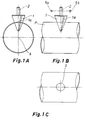
- figs. 1A, B and C
- depict the implementation of a first sequence of the method from various aspects;
- figs. 2A and B
- depict the implementation of a second sequence of the method;
- figs. 3A and B
- depict the implementation of a third sequence of the method:
- figs. 4A and B
- show an apparatus according to a first embodiment of the invention for controlling the actions of a conical drill;
- figs. 5A and B
- show an apparatus according to a second embodiment of the invention for controlling the actions of a conical drill and
- fig. 6
- illustrates the actions of a conical drill in an alternative method of the invention.
- First, a method according to the first embodiment of the invention will be described with reference to figs. 1-3.
- The method is carried out with a conically
shaped tool 1, having a conical surface which is provided withbits 1a on diametrally opposite sides thereof. Theconical drill 1 is rotated around acentre axis 2. Therotating axis 2 extends through apipe centre axis 6. - In the first sequence of the method, the
conical drill 1 is used to drill through the wall of a pipe P to a desired depth. This results in ahole 3, having a width which corresponds to that of a finished hole. Thus, the drilling depth determines the width of a hole. In this drilling sequence, theconical bit 1 is pushed in the direction of therotating axis 2. - In the second sequence, the
conical bit 1 is tilted relative to apivot point 5a located above the top pipe surface. Thepivot point 5a is offset from a mid-line 4 in the direction of tilting. Upon tilting, theconical drill 1 rises upward and moves forward in the longitudinal direction of a pipe. Thus, the rotatingconical drill 1 mills one end 3.1 of an elliptical hole into the shape shown in fig. 2. The adjustment of an angle of inclination a of thedrill 1 can be used for determining the length of a finished hole in relation to the width thereof. - For the third sequence of the method, the
conical drill 1 is first returned to an initial position corresponding to fig. 1, wherein theaxis 2 coincides with the mid-line 4. This is followed by effecting a corresponding lift and concurrent tilting about apivot point 5b in the opposite direction, theconical drill 1 milling the other end 3.2 of the elliptical hole. - The same tool can be used for making holes of varying sizes and degrees of ellipticity since the first-sequence drilling depth and the second- and third-sequence angle of inclination are selectable or adjustable. In this context, the term degree of ellipticity is intended to refer to a hole of any elongated shape, having curved end edges but possibly also linear edge portions.
- Figs. 4A and 4B illustrate an apparatus according to a first embodiment for carrying out the above-described method. The apparatus includes a drive unit 7 provided with a rotating shaft for carrying a
conical drill 1. The drive unit 7 includes ahousing 8 provided with supportinglegs 9 extending therefrom and movable in axial direction relative to thehousing 8. The bottom ends of the supportinglegs 9 are provided on either side of thedrill 1 withbrackets 10 which are fitted withjournals slots 12 included inbrackets 11. Thebrackets 11 are secured to abase plate 13 which, in turn, is attached to clampinghoops 14 engageable around a pipe P. - Thus, the
elements journals slots 12. This is followed by carrying out a drilling operation according to theabove sequence 1, whereby the supportinglegs 9 slide inwards, thehousing 8 approaches the pipe P and theconical drill 1 penetrates the pipe. Thebracket 10 is fitted with abackstop 18 which determines a drilling depth as a sleeve included in the supportingleg 9 collides with thebackstop 18. The vertical position of saidbackstop 18 is adjustable for adjusting the drilling depth. - This is followed by performing the tilting of the tool 7 and the
conical drill 1 included therein about either one of thepivot journals bracket 10 is also inclined relative to thebracket 11. The inclination is limited by means of apin 15, which is fitted in aslot 16 included in thebracket 11 and which collides with the floor of aslot 17 included in thebracket 10. The height of said limitingpin 15 can be adjusted for adjusting the angle of inclination. - Figs. 5A and 5B illustrate an apparatus according to a second embodiment, the identical elements being designated with the same reference numerals as in figs. 4A and 4B. Also in this case the
brackets 11 are secured to a pipe P by means of abase frame 13 andelements 14 engaging around the pipe (the dash-and-dot line refers e.g. to a chain). However, thebracket 11 only includes a single slot 12' receiving a single pivot journal 5' on either side of the drilling axis. On the drilling axis is mounted afitting element 20 with the chuck end of aconical drill 1 secured therein. Thefitting element 20 is surrounded by abushing 19, adapted to be non-rotatable but axially movable relative to thefitting element 20. Thebushing 19 can be clamped e.g. with a screw 21 at a desired axial height relative to thefitting element 20. As theconical drill 1 penetrates the pipe P to a desired depth, the lower end surface ofbushing 19 collides with the top surface of pipe P and, thus, determines the drilling depth. Tilting of the drill apparatus 7 results in apivot point 5a' or 5b', sliding longitudinally of the pipe and located between the end edge ofbushing 19 and the top surface of pipe P. During the course of tilting, the supportinglegs 9 slide outwards and the pivot journals 5' can be locked to the floor of said slot 12'. Alternatively, the pivot journals 5' may rise within the slot 12'. Theinclination limiting pin 15 collides with a slantingwall 17 included in the slot of saidbracket 10. - The
pin 15 can be secured at various heights within theslot 16 for adjusting the angle of inclination. - In the above cases, the mid-section of a hole is drilled first. As shown in fig. 6, it is also possible to proceed in reverse order, whereby the drilling is commenced at the end of a hole, progress is made towards the middle of a hole while increasing the drilling depth and, following the midsection of a hole, the drilling depth is reduced and the drill is lifted up at the other end of a hole. In the case of fig. 6, this alternative method is shown to be implemented by maintaining the drilling axis in vertical direction at all times. In view of engineering, this can be accomplished by means of the computer control or jig control of actions effected in the direction of X-and Y-coordinates. Also in such versions of the apparatus, which involve tilting of the drilling axis, it is possible to employ various combinations of pivoted axles and jig controls. The locations of pivoted axles shown in connection with figs. 4 and 5 result in a preferred mechanical construction but, naturally, an equivalent action can be accomplished with highly diversified dispositions of pivoted axles. An essential feature in the invention is that, during the course of drilling effected by means of a conical drill, the drill is maneuvered simultaneously both in the longitudinal direction and transverse direction of a pipe away from or towards the centre axis.
Claims (5)
- A method for making an elongated hole in a pipe (P) by means of a rotating conical tool (1) whereby, in a first sequence, the rotating conical tool is used for drilling through the pipe wall by pushing the conical tool in the direction of its rotating axis (2) to a desired depth, which determines the width of a finished hole, characterized in that, in a second sequence, the conical bit (1) is lifted from said depth and simultaneously tilted whereby, upon rotating, said conical tool mills one end (3.1) of an elongated hole and a third sequence involves the identical lift of said conical tool (1) and tilting thereof in the opposite direction, said rotating conical bit milling another end (3.2) of said elongated hole, whereby the tilting is effected relative to a pivot point (5a, 5b, 5') located above the top pipe surface and in a plane extending through a centre axis (6) of said pipe (P), an angle of inclination (α) being adjusted for determining the length of a finished hole.
- An apparatus for making an elongated hole in a pipe (P), said apparatus comprising a conical tool (1) for making a hole, a drive means (7) for rotating the conical tool, a housing (8) for the drive means, supporting legs (9) mounted on the housing (8) slidably in axial direction, and supporting and aligning elements (10-14) for supporting and aligning the supporting legs (9) relative to the pipe (P), characterized in that the supporting and aligning elements (10-14) include bracket elements (10 and 11), which on the one hand are engageable to the supporting legs (9) and on the other hand to the pipe (P) and which are braced to each other with at least one pivoted axle (5a, 5b; 5'), which is transverse to the axial direction of the pipe (P) and allows tilting of the drive means (7, 8) relative to the pipe (P) within a certain range, that the bracket elements (10 and 11) are provided with inclination limiting means (15, 16, 17) which can be adjusted for limiting the inclination to various angles of inclination.
- An apparatus as set forth in claim 2, characterized in that it further includes drilling depth limiting elements (18; 19).
- An apparatus as set forth in claim 2 or 3, characterized in that the pivoted axles (5a, 5b) or pivoting fulcrums (5a', 5b') are offset from the drilling axis.
- An apparatus as set forth in claim 4, characterized in that the pivoted axles (5a, 5b) or pivoting fulcrums (5a', 5b') are located flush with or above the top surface of said pipe (P).
Applications Claiming Priority (3)
| Application Number | Priority Date | Filing Date | Title |
|---|---|---|---|
| FI942671A FI101612B (en) | 1994-06-07 | 1994-06-07 | Method and apparatus for making a longitudinal hole in a pipe |
| FI942671 | 1994-06-07 | ||
| PCT/FI1995/000325 WO1995033591A1 (en) | 1994-06-07 | 1995-06-07 | Method and apparatus for making a longitudinal hole in a pipe |
Publications (2)
| Publication Number | Publication Date |
|---|---|
| EP0764068A1 EP0764068A1 (en) | 1997-03-26 |
| EP0764068B1 true EP0764068B1 (en) | 1999-09-15 |
Family
ID=8540865
Family Applications (1)
| Application Number | Title | Priority Date | Filing Date |
|---|---|---|---|
| EP95920919A Expired - Lifetime EP0764068B1 (en) | 1994-06-07 | 1995-06-07 | Method and apparatus for making a longitudinal hole in a pipe |
Country Status (10)
| Country | Link |
|---|---|
| US (1) | US5876161A (en) |
| EP (1) | EP0764068B1 (en) |
| JP (1) | JP3553602B2 (en) |
| KR (1) | KR100250410B1 (en) |
| AT (1) | ATE184528T1 (en) |
| BR (1) | BR9508184A (en) |
| DE (1) | DE69512234T2 (en) |
| ES (1) | ES2136858T3 (en) |
| FI (1) | FI101612B (en) |
| WO (1) | WO1995033591A1 (en) |
Families Citing this family (11)
| Publication number | Priority date | Publication date | Assignee | Title |
|---|---|---|---|---|
| EP1160036A1 (en) * | 2000-05-18 | 2001-12-05 | Visteon Global Technologies, Inc. | Method for machining openings in workpieces |
| FI117327B (en) * | 2004-03-26 | 2006-09-15 | T Drill Oy | Device for forming an oval hole in a pipe wall |
| JP4862453B2 (en) * | 2006-03-30 | 2012-01-25 | アイシン・エィ・ダブリュ株式会社 | Automatic transmission and method of manufacturing impeller hub used therein |
| US20100037444A1 (en) * | 2008-08-15 | 2010-02-18 | Reid Eric M | Reconfigurable flexible rail apparatus and method |
| FR2967086B1 (en) * | 2010-11-05 | 2013-07-12 | Dassault Aviat | ROTATING TOOL FOR DRILLING A HOLE IN A MECHANICAL PART, DEVICE AND METHOD FOR DRILLING THEREFOR |
| JP6286710B2 (en) * | 2014-03-04 | 2018-03-07 | 川崎建設株式会社 | Underdrain drainage pipe cleaning device |
| US10371287B2 (en) * | 2014-09-19 | 2019-08-06 | Geomatrix, LLC | Alignment orifice shield |
| DE102015213585A1 (en) * | 2015-07-20 | 2017-01-26 | Homag Holzbearbeitungssysteme Gmbh | Method and device for forming a recess |
| DE102015222529A1 (en) * | 2015-11-16 | 2017-05-18 | Siemens Aktiengesellschaft | Milling device and method for performing a milling operation within a groove |
| EP3431732B1 (en) | 2017-07-21 | 2020-04-22 | Bosal Emission Control Systems NV | Method for forming a collar in a muffler housing |
| CN112158354B (en) * | 2020-08-21 | 2021-12-10 | 成都飞机工业(集团)有限责任公司 | Method for determining depth of automatic countersink of airplane |
Family Cites Families (25)
| Publication number | Priority date | Publication date | Assignee | Title |
|---|---|---|---|---|
| US1886082A (en) * | 1930-04-08 | 1932-11-01 | Great Lakes Aircraft Corp | Radius forming fixture |
| US2499842A (en) * | 1945-11-23 | 1950-03-07 | Kearney & Trecker Corp | Milling machine |
| US2823591A (en) * | 1953-11-13 | 1958-02-18 | Kaiser Metal Products Inc | Tool adjustment |
| US2969000A (en) * | 1957-09-24 | 1961-01-24 | Cleaver Brooks Co | Chamfering tool |
| US3241405A (en) * | 1965-01-08 | 1966-03-22 | John H Davis | Countersink tool |
| US3596558A (en) * | 1969-05-16 | 1971-08-03 | Edmund W F Rydell | Magnetic base milling machine |
| US3699828A (en) * | 1970-12-02 | 1972-10-24 | Victaulic Co Of America | Pipe groover |
| DE2113746A1 (en) * | 1971-03-22 | 1972-09-28 | Metz Reglerbau Gmbh | Method and device for the production of molded parts from sheet material |
| SU546438A1 (en) * | 1975-08-25 | 1977-02-15 | Предприятие П/Я Р-6476 | Device for processing internal surfaces of rotation with curvilinear generatrix |
| FR2327013A1 (en) * | 1975-10-09 | 1977-05-06 | Robles Joseph | Milling cutter for sheet holes - has cutter centralised on existing small dia. hole using conical form cutter |
| SU589091A1 (en) * | 1976-09-13 | 1978-01-25 | Предприятие П/Я Г-4967 | Method of making the hammer slot |
| JPS5442088A (en) * | 1977-09-07 | 1979-04-03 | Ntn Toyo Bearing Co Ltd | Method for providing a window hole in a cylindrical blank |
| DE2749287A1 (en) * | 1977-11-03 | 1979-05-10 | Schwab Inh Helmut Schwab Masch | Pipe wall circular hole milling tool - is connected to copying mechanism supporting on pipe wall, both tool and copier being mounted on slides |
| FR2493755A1 (en) * | 1980-11-13 | 1982-05-14 | Petroles Cie Francaise | METHOD FOR REMOVING A CONCRETE COATING, IN PARTICULAR ON A CONDUIT AND DEVICE FOR IMPLEMENTING SAID METHOD |
| FI820204L (en) * | 1981-03-10 | 1982-09-11 | Serlachius Oy | ANORDNING FOER ATT GOERA ETT OVALT HAOL I EN ROERVAEGG |
| DE3503300A1 (en) * | 1985-01-31 | 1986-08-07 | Rudi 7080 Aalen Körner | Milling machine |
| SU1335383A1 (en) * | 1986-01-13 | 1987-09-07 | Научно-Производственное Объединение По Технологии Машиностроения "Цниитмаш" | Method of making oval hole in cylindrical articles for flanging a branch pipe |
| US4729698A (en) * | 1986-09-05 | 1988-03-08 | Haddon Jesse E | Multi-purpose and versatile portable power tool |
| US4743149A (en) * | 1987-03-13 | 1988-05-10 | Specialty Tool Co., Inc. | Header tube tool |
| EP0326156B1 (en) * | 1988-01-27 | 1993-05-05 | Kabushiki Kaisha Iseki Kaihatsu Koki | Apparatus for conducting operation in pipe |
| FR2661758B1 (en) * | 1990-05-04 | 1992-11-27 | Aerospatiale | METHOD AND SYSTEM FOR THE PRODUCTION OF A FLAT REFERENCE SURFACE, DEFINED BY A DETERMINED EQUATION, ON AN ASSEMBLY BOX OF A STRUCTURE, FROM A GROSS SURFACE. |
| US5201618A (en) * | 1991-09-24 | 1993-04-13 | General Motors Corporation | Method for machining an ellipitical bore |
| JP3295110B2 (en) * | 1991-10-07 | 2002-06-24 | 東芝機械株式会社 | Saddle swivel head |
| SE9300400L (en) * | 1993-02-05 | 1994-08-06 | Strukturteknologier I Stockhol | Machine tool for receiving a through opening in a fiber composite article |
| US5368423A (en) * | 1994-02-03 | 1994-11-29 | Inliner U.S.A., Inc. | Robotic cutter |
-
1994
- 1994-06-07 FI FI942671A patent/FI101612B/en not_active IP Right Cessation
-
1995
- 1995-06-07 US US08/750,463 patent/US5876161A/en not_active Expired - Lifetime
- 1995-06-07 JP JP50040796A patent/JP3553602B2/en not_active Expired - Lifetime
- 1995-06-07 AT AT95920919T patent/ATE184528T1/en not_active IP Right Cessation
- 1995-06-07 DE DE69512234T patent/DE69512234T2/en not_active Expired - Lifetime
- 1995-06-07 EP EP95920919A patent/EP0764068B1/en not_active Expired - Lifetime
- 1995-06-07 KR KR1019960706985A patent/KR100250410B1/en not_active Expired - Lifetime
- 1995-06-07 ES ES95920919T patent/ES2136858T3/en not_active Expired - Lifetime
- 1995-06-07 WO PCT/FI1995/000325 patent/WO1995033591A1/en not_active Ceased
- 1995-06-07 BR BR9508184A patent/BR9508184A/en not_active IP Right Cessation
Also Published As
| Publication number | Publication date |
|---|---|
| ATE184528T1 (en) | 1999-10-15 |
| KR100250410B1 (en) | 2000-04-01 |
| FI942671L (en) | 1995-12-08 |
| BR9508184A (en) | 1997-08-12 |
| EP0764068A1 (en) | 1997-03-26 |
| JPH10500906A (en) | 1998-01-27 |
| US5876161A (en) | 1999-03-02 |
| FI101612B1 (en) | 1998-07-31 |
| FI101612B (en) | 1998-07-31 |
| JP3553602B2 (en) | 2004-08-11 |
| DE69512234T2 (en) | 2000-05-18 |
| DE69512234D1 (en) | 1999-10-21 |
| ES2136858T3 (en) | 1999-12-01 |
| FI942671A0 (en) | 1994-06-07 |
| WO1995033591A1 (en) | 1995-12-14 |
Similar Documents
| Publication | Publication Date | Title |
|---|---|---|
| US5876161A (en) | Method and apparatus for making a longitudinal hole in a pipe | |
| US20070193780A1 (en) | Drilling device and method for producing undercut holes | |
| US7140813B2 (en) | Line boring machine | |
| RU2087310C1 (en) | Drill jig for originating of holes with relieving | |
| JP2846250B2 (en) | Drilling device for making a drilled hole with an undercut | |
| CN107627407A (en) | A kind of wood processing equipment | |
| JP2002018575A (en) | Spiral blade automatic processing machine | |
| US5527210A (en) | Dynamic steady rest | |
| CN207224175U (en) | A kind of wood processing machine | |
| GB2272391A (en) | Drilling jig | |
| US5595226A (en) | Drilling/cutting machine for making joints in wooden members | |
| CN206840331U (en) | A kind of timber precision drilling device | |
| CN221538870U (en) | Numerical control lathe with height-adjustable operating platform | |
| CN207224180U (en) | A kind of machine and wood cutting | |
| CN207240398U (en) | A kind of timber side processing machine | |
| CN207224168U (en) | A kind of wood drilling machine | |
| CN112757084A (en) | Building site uses multi-functional cutting equipment | |
| CN219542610U (en) | Steel plate groove processing device | |
| KR102916487B1 (en) | Cutting method of pipe cutting unit | |
| CN220029573U (en) | Automatic drilling equipment | |
| CN217808498U (en) | Cement concrete paver elevation control auxiliary device | |
| IE65042B1 (en) | A work piece stabilising device | |
| JPH0223323B2 (en) | ||
| US5713114A (en) | Apparatus for shaping elongated workpieces | |
| WO1998024613A1 (en) | Welding device for plastic pipes |
Legal Events
| Date | Code | Title | Description |
|---|---|---|---|
| PUAI | Public reference made under article 153(3) epc to a published international application that has entered the european phase |
Free format text: ORIGINAL CODE: 0009012 |
|
| 17P | Request for examination filed |
Effective date: 19961220 |
|
| AK | Designated contracting states |
Kind code of ref document: A1 Designated state(s): AT BE CH DE DK ES FR GB GR IE IT LI NL PT SE |
|
| GRAG | Despatch of communication of intention to grant |
Free format text: ORIGINAL CODE: EPIDOS AGRA |
|
| 17Q | First examination report despatched |
Effective date: 19981217 |
|
| GRAG | Despatch of communication of intention to grant |
Free format text: ORIGINAL CODE: EPIDOS AGRA |
|
| GRAH | Despatch of communication of intention to grant a patent |
Free format text: ORIGINAL CODE: EPIDOS IGRA |
|
| GRAH | Despatch of communication of intention to grant a patent |
Free format text: ORIGINAL CODE: EPIDOS IGRA |
|
| GRAA | (expected) grant |
Free format text: ORIGINAL CODE: 0009210 |
|
| AK | Designated contracting states |
Kind code of ref document: B1 Designated state(s): AT BE CH DE DK ES FR GB GR IE IT LI NL PT SE |
|
| PG25 | Lapsed in a contracting state [announced via postgrant information from national office to epo] |
Ref country code: NL Free format text: LAPSE BECAUSE OF FAILURE TO SUBMIT A TRANSLATION OF THE DESCRIPTION OR TO PAY THE FEE WITHIN THE PRESCRIBED TIME-LIMIT Effective date: 19990915 Ref country code: LI Free format text: LAPSE BECAUSE OF FAILURE TO SUBMIT A TRANSLATION OF THE DESCRIPTION OR TO PAY THE FEE WITHIN THE PRESCRIBED TIME-LIMIT Effective date: 19990915 Ref country code: GR Free format text: LAPSE BECAUSE OF NON-PAYMENT OF DUE FEES Effective date: 19990915 Ref country code: CH Free format text: LAPSE BECAUSE OF FAILURE TO SUBMIT A TRANSLATION OF THE DESCRIPTION OR TO PAY THE FEE WITHIN THE PRESCRIBED TIME-LIMIT Effective date: 19990915 Ref country code: BE Free format text: LAPSE BECAUSE OF FAILURE TO SUBMIT A TRANSLATION OF THE DESCRIPTION OR TO PAY THE FEE WITHIN THE PRESCRIBED TIME-LIMIT Effective date: 19990915 Ref country code: AT Free format text: LAPSE BECAUSE OF FAILURE TO SUBMIT A TRANSLATION OF THE DESCRIPTION OR TO PAY THE FEE WITHIN THE PRESCRIBED TIME-LIMIT Effective date: 19990915 |
|
| REF | Corresponds to: |
Ref document number: 184528 Country of ref document: AT Date of ref document: 19991015 Kind code of ref document: T |
|
| REG | Reference to a national code |
Ref country code: CH Ref legal event code: EP |
|
| ITF | It: translation for a ep patent filed | ||
| REF | Corresponds to: |
Ref document number: 69512234 Country of ref document: DE Date of ref document: 19991021 |
|
| REG | Reference to a national code |
Ref country code: IE Ref legal event code: FG4D |
|
| REG | Reference to a national code |
Ref country code: ES Ref legal event code: FG2A Ref document number: 2136858 Country of ref document: ES Kind code of ref document: T3 |
|
| ET | Fr: translation filed | ||
| PG25 | Lapsed in a contracting state [announced via postgrant information from national office to epo] |
Ref country code: PT Free format text: LAPSE BECAUSE OF FAILURE TO SUBMIT A TRANSLATION OF THE DESCRIPTION OR TO PAY THE FEE WITHIN THE PRESCRIBED TIME-LIMIT Effective date: 19991215 Ref country code: DK Free format text: LAPSE BECAUSE OF FAILURE TO SUBMIT A TRANSLATION OF THE DESCRIPTION OR TO PAY THE FEE WITHIN THE PRESCRIBED TIME-LIMIT Effective date: 19991215 |
|
| NLV1 | Nl: lapsed or annulled due to failure to fulfill the requirements of art. 29p and 29m of the patents act | ||
| REG | Reference to a national code |
Ref country code: CH Ref legal event code: PL |
|
| PG25 | Lapsed in a contracting state [announced via postgrant information from national office to epo] |
Ref country code: IE Free format text: LAPSE BECAUSE OF NON-PAYMENT OF DUE FEES Effective date: 20000607 |
|
| PLBE | No opposition filed within time limit |
Free format text: ORIGINAL CODE: 0009261 |
|
| STAA | Information on the status of an ep patent application or granted ep patent |
Free format text: STATUS: NO OPPOSITION FILED WITHIN TIME LIMIT |
|
| 26N | No opposition filed | ||
| REG | Reference to a national code |
Ref country code: IE Ref legal event code: MM4A |
|
| REG | Reference to a national code |
Ref country code: GB Ref legal event code: IF02 |
|
| PGFP | Annual fee paid to national office [announced via postgrant information from national office to epo] |
Ref country code: GB Payment date: 20140618 Year of fee payment: 20 |
|
| PGFP | Annual fee paid to national office [announced via postgrant information from national office to epo] |
Ref country code: DE Payment date: 20140619 Year of fee payment: 20 Ref country code: SE Payment date: 20140618 Year of fee payment: 20 Ref country code: ES Payment date: 20140624 Year of fee payment: 20 |
|
| PGFP | Annual fee paid to national office [announced via postgrant information from national office to epo] |
Ref country code: FR Payment date: 20140619 Year of fee payment: 20 |
|
| PGFP | Annual fee paid to national office [announced via postgrant information from national office to epo] |
Ref country code: IT Payment date: 20140630 Year of fee payment: 20 |
|
| REG | Reference to a national code |
Ref country code: DE Ref legal event code: R071 Ref document number: 69512234 Country of ref document: DE |
|
| REG | Reference to a national code |
Ref country code: GB Ref legal event code: PE20 Expiry date: 20150606 |
|
| PG25 | Lapsed in a contracting state [announced via postgrant information from national office to epo] |
Ref country code: GB Free format text: LAPSE BECAUSE OF EXPIRATION OF PROTECTION Effective date: 20150606 |
|
| REG | Reference to a national code |
Ref country code: SE Ref legal event code: EUG |
|
| REG | Reference to a national code |
Ref country code: ES Ref legal event code: FD2A Effective date: 20150925 |
|
| PG25 | Lapsed in a contracting state [announced via postgrant information from national office to epo] |
Ref country code: ES Free format text: LAPSE BECAUSE OF EXPIRATION OF PROTECTION Effective date: 20150608 |