EP0763834A2 - Tap changer - Google Patents
Tap changer Download PDFInfo
- Publication number
- EP0763834A2 EP0763834A2 EP96112980A EP96112980A EP0763834A2 EP 0763834 A2 EP0763834 A2 EP 0763834A2 EP 96112980 A EP96112980 A EP 96112980A EP 96112980 A EP96112980 A EP 96112980A EP 0763834 A2 EP0763834 A2 EP 0763834A2
- Authority
- EP
- European Patent Office
- Prior art keywords
- switching
- diverter switch
- load
- switch
- cells
- Prior art date
- Legal status (The legal status is an assumption and is not a legal conclusion. Google has not performed a legal analysis and makes no representation as to the accuracy of the status listed.)
- Granted
Links
Images

Classifications
-
- H—ELECTRICITY
- H01—ELECTRIC ELEMENTS
- H01H—ELECTRIC SWITCHES; RELAYS; SELECTORS; EMERGENCY PROTECTIVE DEVICES
- H01H9/00—Details of switching devices, not covered by groups H01H1/00 - H01H7/00
- H01H9/0005—Tap change devices
- H01H9/0038—Tap change devices making use of vacuum switches
-
- H—ELECTRICITY
- H01—ELECTRIC ELEMENTS
- H01F—MAGNETS; INDUCTANCES; TRANSFORMERS; SELECTION OF MATERIALS FOR THEIR MAGNETIC PROPERTIES
- H01F29/00—Variable transformers or inductances not covered by group H01F21/00
- H01F29/02—Variable transformers or inductances not covered by group H01F21/00 with tappings on coil or winding; with provision for rearrangement or interconnection of windings
- H01F29/04—Variable transformers or inductances not covered by group H01F21/00 with tappings on coil or winding; with provision for rearrangement or interconnection of windings having provision for tap-changing without interrupting the load current
Definitions
- the invention relates to a tap changer for tap transformers according to the preamble of the first claim.
- a step transformer is known from European patent application 644562.
- This known tap changer has a tap selector and the actual diverter switch.
- the tap selector has a separate vacuum switching cell for each tap of the tap winding, by means of which the corresponding tap can be connected to the diverter switch.
- Fig. 1 shows the circuit of such a known tap changer.
- 19 taps of the step winding are provided, each of which is assigned a vacuum switching cell VB1 ... VB19 of the step selector W.
- the derivation of the vacuum switching cells VB2, VB4,... Assigned to the even-numbered step contacts is electrically connected to the first side La of the diverter switch LU; the derivation of the vacuum switching cells VB1, VB3,.
- the diverter switch LU consists of 3 GTO bridges, the structure of which is shown in detail in Fig. 1a.
- the winding taps are preset without current, ie the respective vacuum switching cell is switched without power. Only after the preselection has been completed does the actual switchover under load to the new pre-selected winding tapping take place in the LU changeover switch using the switching electronics, the heart of which is the GTO bridges.
- a disadvantage of this known tap changer is the high circuit complexity in the diverter switch, which is due in particular to the required thyristors, diodes and varistors.
- the object of the invention is to provide a further developed tap changer which, while maintaining the fast connection possibility of the different Winding taps through respective vacuum switch cells has a significantly simplified diverter switch.
- the diverter switch only requires an additional switching choke; the entire switching electronics according to the prior art is omitted.
- Another advantage of the invention is that the existing vacuum switching cells are switched with an arc, ie under load; The arcing causes the vacuum switch cells to be conditioned, which improves their surge voltage resistance in the open state.
- the tap changer maintains the tap selector known from the prior art.
- a vacuum switch cell VB1 ... VB19 As already explained above, the derivatives of the even-numbered vacuum switch cells VB2, VB4, ... lead to the first branch La, those of the odd-numbered vacuum switch cells VB1, VB3, ... to the second branch Lb of the diverter switch LU.
- a further vacuum switching cell VAC1, VAC2 is connected in each of the two branches La, Lb, the derivation of which leads to the load dissipation.
- a switching reactance Xü is connected between these two vacuum switching points VAC1, VAC2.
- the switching sequence for a circuit can be seen from FIG. 3. As a first step, VAC2 is closed, then VAC1 is opened, then VB19 is closed and then again - and finally the entire load switchover - VB18 is opened.
- the vacuum switch cells are operated under load, ie with arcing. In the downshift shown in FIG. 4 again at position 18, this switching sequence takes place in a correspondingly opposite sequence.
- each switching process begins with a circuit of one of the two vacuum switch cells of the diverter switch and is completed by a switching process of one of the vacuum switch cells in the selector.
- the vacuum switching cells VB1 ... VB19 are used twice in the selector; on the one hand, these serve for preselection of the levels and, on the other hand, are also part of the load switchover.
- the vacuum switch cells can only be used in the selector in order to achieve a quick changeover with short switching paths, their electrical potential there remains largely untapped.
- the invention makes good use of the good electrical switching properties of vacuum switching cells in that, as explained, VB1 ... VB19 is included in the actual load switching process. This makes it possible to dispense with the entire complex switching electronics by adding a single switching reactance Xü. At the same time, the difficulty is avoided that GTOs can only be used for limited performance ranges.
- the invention also has the advantage of lower power loss. In the prior art according to FIG. 1, one of the GTO bridges, referred to there as GTO C, always has current flowing through it, which leads to power loss. This is not the case with the invention.
Abstract
Description
Die Erfindung betrifft einen Stufenschalter für Stufentransformatoren gemäß dem Oberbegriff des ersten Patentanspruches. Ein solcher Stufentransformator ist aus der Europäischen Patentanmeldung 644562 bekannt.The invention relates to a tap changer for tap transformers according to the preamble of the first claim. Such a step transformer is known from European patent application 644562.
Dieser bekannte Stufenschalter weist einen Stufenwähler und den eigentlichen Lastumschalter auf.
Der Stufenwähler besitzt dabei für jede Wicklungsanzapfung der Stufenwicklung eine separate Vakuumschaltzelle, mittels der die entsprechende Wicklungsanzapfung mit dem Lastumschalter verbindbar ist.This known tap changer has a tap selector and the actual diverter switch.
The tap selector has a separate vacuum switching cell for each tap of the tap winding, by means of which the corresponding tap can be connected to the diverter switch.
Fig. 1 zeigt die Schaltung eines solchen bekannten Stufenschalters. Dabei sind 19 Anzapfungen der Stufenwicklung vorgesehen denen jeweils eine Vakuumschaltzelle VB1 ... VB19 des Stufenwählers W zugeordnet ist.
Die Ableitung der den geradzahligen Stufenkontakten zugeordneten Vakuumschaltzellen VB2, VB4, ... ist mit der ersten Seite La des Lastumschalters LU elektrisch verbunden; die Ableitung der den ungeradzahligen Stufenkontakten zugeordneten Vakuumschaltzellen VB1, VB3, ... ist mit der zweiten Seite Lb des Lastumschalters LU elektrisch verbunden, so daß eine Lastumschaltung von einem bisher stromführenden Stufenkontakt zu einem benachbarten vorgewählten Stufenkontakt möglich ist.Fig. 1 shows the circuit of such a known tap changer. 19 taps of the step winding are provided, each of which is assigned a vacuum switching cell VB1 ... VB19 of the step selector W.
The derivation of the vacuum switching cells VB2, VB4,... Assigned to the even-numbered step contacts is electrically connected to the first side La of the diverter switch LU; the derivation of the vacuum switching cells VB1, VB3,.
Der Lastumschalter LU besteht dabei aus 3 GTO-Brücken, deren Aufbau im einzelnen aus Fig. 1a ersichtlich ist.
Bei diesem bekannten Stufenschalter werden die Wicklungsanzapfungen stromlos voreingestellt, d. h. die jeweilige Vakuumschaltzelle wird leistungslos geschaltet. Erst nach abgeschlossener Vorwahl erfolgt im Lastumschalter LU mittels der Schaltelektronik, deren Herzstück die GTO-Brücken sind, die eigentliche Umschaltung unter Last auf die neue vorgewählte Wicklungsanzapfung.
Nachteilig an diesem bekannten Stufenschalter ist der hohe schaltungstechnische Aufwand im Lastumschalter, der insbesondere durch die erforderlichen Thyristoren, Dioden und Varistoren bedingt ist.The diverter switch LU consists of 3 GTO bridges, the structure of which is shown in detail in Fig. 1a.
In this known tap changer, the winding taps are preset without current, ie the respective vacuum switching cell is switched without power. Only after the preselection has been completed does the actual switchover under load to the new pre-selected winding tapping take place in the LU changeover switch using the switching electronics, the heart of which is the GTO bridges.
A disadvantage of this known tap changer is the high circuit complexity in the diverter switch, which is due in particular to the required thyristors, diodes and varistors.
Aufgabe der Erfindung ist es, einen weiterentwickelten Stufenschalter anzugeben, der bei Beibehaltung der schnellen Anschaltmöglichkeit der unterschiedlichen Wicklungsanzapfungen durch jeweilige Vakuumschaltzellen einen wesentlich vereinfachten Lastumschalter aufweist.The object of the invention is to provide a further developed tap changer which, while maintaining the fast connection possibility of the different Winding taps through respective vacuum switch cells has a significantly simplified diverter switch.
Diese Aufgabe wird durch die Erfindung gelöst.
Besonders vorteilhaft ist dabei, daß der Lastumschalter lediglich eine zusätzliche Überschaltdrossel benötigt; die gesamte Schaltelektronik nach dem Stand der Technik entfällt dabei. Ein weiterer Vorteil der Erfindung besteht dabei darin, daß die vorhandenen Vakuumschaltzellen mit Lichtbogen, d. h. unter Last geschaltet werden; durch die Lichtbögen erfolgt dabei eine Konditionierung der Vakuumschaltzellen, was deren Stoßspannungsfestigkeit im geöffneten Zustand verbessert.This object is achieved by the invention.
It is particularly advantageous that the diverter switch only requires an additional switching choke; the entire switching electronics according to the prior art is omitted. Another advantage of the invention is that the existing vacuum switching cells are switched with an arc, ie under load; The arcing causes the vacuum switch cells to be conditioned, which improves their surge voltage resistance in the open state.
Die Erfindung soll nachfolgend anhand eines Ausführungsbeispiels noch naher erläutert werden.
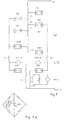
- Fig. 2 zeigt die Schaltung eines erfindungsgemäßen Stufenschalters.
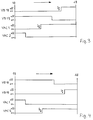
- Fig. 3 zeigt eine Schaltsequenz bei einer Umschaltung von
Stellung 18 aufStellung 19 und - Fig. 4 zeigt eine solche Schaltsequenz bei der Umschaltung von
Stellung 19 wieder zurück aufStellung 18.
- Fig. 2 shows the circuit of a tap changer according to the invention.
- Fig. 3 shows a switching sequence when switching from
position 18 toposition 19 and - 4 shows such a switching sequence when switching from
position 19 back toposition 18.
Aus Fig. 2 ist ersichtlich, daß der erfindungsgemäße Stufenschalter den nach dem Stand der Technik bekannten Stufenwähler beibehält. Dort sind 19 Anzapfungen der Stufenwicklung und damit mögliche Stellungen vorgesehen, wobei jede Anzapfung durch eine Vakuumschaltzelle VB1 ... VB19 anschaltbar ist. Wie bereits weiter oben erläutert, führen die Ableitungen der geradzahligen Vakuumschaltzellen VB2, VB4, ... zum ersten Zweig La, die der ungeradzahligen Vakuumschaltzellen VB1, VB3, ... zum zweiten Zweig Lb des Lastumschalters LU. Erfindungsgemäß ist in jeden der beiden Zweige La, Lb eine weitere Vakuumschaltzelle VAC1, VAC2 geschaltet, deren Ableitung zur Lastableitung führt. Auf der der Lastableitung jeweils abgewandten Seite ist zwischen diesen beiden Vakuumschaltsellen VAC1, VAC2 eine Überschaltreaktanz Xü geschaltet.From Fig. 2 it can be seen that the tap changer according to the invention maintains the tap selector known from the prior art. There are 19 taps of the step winding and thus possible positions, each tap can be switched on by a vacuum switch cell VB1 ... VB19. As already explained above, the derivatives of the even-numbered vacuum switch cells VB2, VB4, ... lead to the first branch La, those of the odd-numbered vacuum switch cells VB1, VB3, ... to the second branch Lb of the diverter switch LU. According to the invention, a further vacuum switching cell VAC1, VAC2 is connected in each of the two branches La, Lb, the derivation of which leads to the load dissipation. On the side facing away from the load derivation, a switching reactance Xü is connected between these two vacuum switching points VAC1, VAC2.
Aus Fig. 3 ist die Schaltsequenz bei einer Schaltung ersichtlich. Als erster Schritt wird VAC2 geschlossen, danach wird VAC1 geöffnet, anschließend wird VB19 geschlossen und wiederum anschließend - und damit die gesamte Lastumschaltung abschließend - wird VB18 geöffnet. Die Betätigung der Vakuumschaltzellen erfolgt jeweils unter Last, d. h. mit Lichtbogenbildung. Bei der in Fig. 4 dargestellten Rückschaltung wiederum auf Stellung 18 läuft diese Schaltsequenz in entsprechend entgegengesetzter Reihenfolge ab.The switching sequence for a circuit can be seen from FIG. 3. As a first step, VAC2 is closed, then VAC1 is opened, then VB19 is closed and then again - and finally the entire load switchover - VB18 is opened. The vacuum switch cells are operated under load, ie with arcing. In the downshift shown in FIG. 4 again at
Aus diesen Darstellungen sind zwei Besonderheiten der Erfindung ersichtlich:
Zum einen ist aus den Schaltsequenzen gut zu erkennen, daß Stufenwahl und eigentliche Lastumschaltung zu einem gemeinsamen Umschaltvorgang vereinigt sind. Während beim Stufenschalter nach dem Stand der Technik zuerst die Vorwahl der neuen Wicklungsanzapfung erfolgt und erst danach, wenn diese Vorwahl beendet ist, der eigentliche Umschaltvorgang im Lastumschalter beginnt, sind diese Vorgange bei der Erfindung kombiniert ablaufend und zeitlich nicht trennbar. Jeder Umschaltvorgang beginnt bei der Erfindung mit einer Schaltung einer der beiden Vakuumschaltzellen des Lastumschalters und wird durch einen Schaltvorgang einer der Vakuumschaltzellen im Wähler abgeschlossen.
Zum anderen erfolgt bei der Erfindung eine doppelte funktionelle Nutzung der Vakuumschaltzellen VB1 ... VB19 im Wähler; diese dienen einerseits zur Stufenvorwahl und sind andererseits auch Bestandteil der Lastumschaltung.Two special features of the invention can be seen from these illustrations:
On the one hand, it can be clearly seen from the switching sequences that stage selection and actual load switching are combined into a common switching process. While in the step switch according to the prior art the preselection of the new winding tapping takes place first and only after this preselection has ended, the actual switching process in the diverter switch begins, these processes in the invention are combined in sequence and cannot be separated in time. In the invention, each switching process begins with a circuit of one of the two vacuum switch cells of the diverter switch and is completed by a switching process of one of the vacuum switch cells in the selector.
On the other hand, in the invention, the vacuum switching cells VB1 ... VB19 are used twice in the selector; on the one hand, these serve for preselection of the levels and, on the other hand, are also part of the load switchover.
Während beim Stand der Technik die Vakuumschaltzellen im Wähler nur eingesetzt werden können, um eine schnelle Umschaltung bei kleinen Schaltwegen zu erzielen, bleibt ihr elektrisches Potential dort weitestgehend unausgeschöpft.
Dagegen nutzt die Erfindung die guten elektrischen Schalteigenschaften von Vakuumschaltzellen allgemein, indem sie, wie erläutert, VB1 ... VB19 in den eigentlichen Lastumschaltvorgang miteinbezieht. Dadurch ist es möglich, durch Hinzufügen einer einzigen Überschaltreaktanz Xü auf die gesamte aufwendige Schaltelektronik zu verzichten. Zugleich wird die Schwierigkeit vermieden, daß GTO's nur für begrenzte Leistungsbereiche einsetzbar sind. Schließlich weist die Erfindung auch den Vorteil einer geringeren Verlustleistung auf. Beim Stand der Technik gemäß Fig. 1 ist eine der GTO-Brücken, dort als GTO C bezeichnet, stets stromdurchflossen, was zu einer Verlustleistung führt. Dies ist bei der Erfindung nicht der Fall.While in the prior art the vacuum switch cells can only be used in the selector in order to achieve a quick changeover with short switching paths, their electrical potential there remains largely untapped.
In contrast, the invention makes good use of the good electrical switching properties of vacuum switching cells in that, as explained, VB1 ... VB19 is included in the actual load switching process. This makes it possible to dispense with the entire complex switching electronics by adding a single switching reactance Xü. At the same time, the difficulty is avoided that GTOs can only be used for limited performance ranges. Finally, the invention also has the advantage of lower power loss. In the prior art according to FIG. 1, one of the GTO bridges, referred to there as GTO C, always has current flowing through it, which leads to power loss. This is not the case with the invention.
Bei unkritischen thermischen Verhältnissen ist es auch möglich, anstelle der beschriebenen Überschaltreaktanz einen Überschaltwiderstand an gleicher Stelle vorzusehen.In the case of uncritical thermal conditions, it is also possible to provide an overrunning resistor at the same point instead of the overreactance described.
Claims (2)
wobei im Stufenwähler für jede zu schaltende Wicklungsanzapfung der Stufenwicklung des Stufentransformators eine separate Vakuumschaltzelle vorgesehen ist, mittels der die jeweilige Wicklungsanzapfung mit dem Lastumschalter verbindbar ist, derart, daß die Ableitungen der den geradzahligen Wicklungsanzapfungen zugeordneten Vakuumschaltzellen elektrisch mit der ersten Seite des Lastumschalters verbunden sind und die Ableitungen der den ungeradzahligen Wicklungsanzapfungen zugeordneten Vakuumschaltzellen elektrisch mit der zweiten Seite des Lastumschalters verbunden sind,
dadurch gekennzeichnet,
daß in jeder der beiden Seiten (La, Lb) des Lastumschalters (LU) eine weitere Vakuumschaltzelle (VAC1, VAC2) geschaltet ist, deren Ableitung elektrisch mit der Lastableitung des Stufenschalters in Verbindung steht
und daß aufder der Lastableitung abgewandten Seite zwischen den beiden weiteren Vakuumschaltzellen (VAC1, VAC2) und damit zwischen den beiden Seiten (La, Lb) des Lastumschalters (LU) eine Überschaltreaktanz (Xü) angeordnet ist.Step switches for step transformers, consisting of a step selector and a diverter switch,
a separate vacuum switching cell is provided in the step selector for each winding tapping of the step winding of the step transformer, by means of which the respective winding tapping can be connected to the diverter switch, such that the leads of the vacuum switching cells associated with the even-numbered winding taps are electrically connected to the first side of the diverter switch and the leads of the vacuum switching cells assigned to the odd-numbered winding taps are electrically connected to the second side of the diverter switch,
characterized,
that a further vacuum switching cell (VAC1, VAC2) is connected in each of the two sides (La, Lb) of the diverter switch (LU), the derivation of which is electrically connected to the load derivation of the tap changer
and that a switching reactance (Xü) is arranged on the side facing away from the load diversion between the two further vacuum switching cells (VAC1, VAC2) and thus between the two sides (La, Lb) of the diverter switch (LU).
dadurch gekennzeichnet, daß anstelle der Überschaltreaktanz (Xü) ein Überschaltwiderstand angeordnet ist.Step switch according to claim 1,
characterized in that, instead of the switching reactance (Xü), a switching resistor is arranged.
Applications Claiming Priority (2)
| Application Number | Priority Date | Filing Date | Title |
|---|---|---|---|
| DE19534544 | 1995-09-18 | ||
| DE19534544A DE19534544A1 (en) | 1995-09-18 | 1995-09-18 | Tap changer |
Publications (3)
| Publication Number | Publication Date |
|---|---|
| EP0763834A2 true EP0763834A2 (en) | 1997-03-19 |
| EP0763834A3 EP0763834A3 (en) | 1997-05-02 |
| EP0763834B1 EP0763834B1 (en) | 1998-04-29 |
Family
ID=7772461
Family Applications (1)
| Application Number | Title | Priority Date | Filing Date |
|---|---|---|---|
| EP96112980A Expired - Lifetime EP0763834B1 (en) | 1995-09-18 | 1996-08-13 | Tap changer |
Country Status (4)
| Country | Link |
|---|---|
| US (1) | US5694034A (en) |
| EP (1) | EP0763834B1 (en) |
| AT (1) | ATE165691T1 (en) |
| DE (2) | DE19534544A1 (en) |
Families Citing this family (7)
| Publication number | Priority date | Publication date | Assignee | Title |
|---|---|---|---|---|
| GB0004885D0 (en) * | 2000-03-01 | 2000-04-19 | Alstom | Improvements in and relating to filers and filter components |
| US7737667B2 (en) * | 2004-10-14 | 2010-06-15 | Utility Systems Technologies, Inc. | 3-phase electronic tap changer commutation and device |
| US8207716B2 (en) * | 2004-10-14 | 2012-06-26 | Utility Systems Technologies, Inc. | Useful improvements in the art of 3-phase electronic tap changer commutation device |
| ES2274684B1 (en) * | 2005-02-15 | 2008-04-16 | Universidad De Sevilla | SHIFT CHANGER FOR MEDIUM / LOW VOLTAGE TRANSFORMERS. |
| US7595614B2 (en) * | 2007-12-07 | 2009-09-29 | Pennsylvania Transformer Technology, Inc. | Load tap changer |
| DE202010011521U1 (en) * | 2010-08-18 | 2011-11-23 | Maschinenfabrik Reinhausen Gmbh | OLTC |
| US9898019B2 (en) * | 2012-12-27 | 2018-02-20 | Xiaoming Li | Thyristor assisted on-load tap changer and method thereof |
Citations (1)
| Publication number | Priority date | Publication date | Assignee | Title |
|---|---|---|---|---|
| EP0644562A1 (en) * | 1993-09-21 | 1995-03-22 | THE NATIONAL GRID COMPANY plc | Electrical changeover switching |
Family Cites Families (5)
| Publication number | Priority date | Publication date | Assignee | Title |
|---|---|---|---|---|
| JPS507727B1 (en) * | 1969-11-04 | 1975-03-28 | ||
| US3783206A (en) * | 1972-07-06 | 1974-01-01 | Westinghouse Electric Corp | Tap changing apparatus with improved contact structure to eliminate electrical fields across open interrupter switches |
| US5488212A (en) * | 1993-10-19 | 1996-01-30 | Fuji Electric Co., Ltd. | Switching device for an on-load tap changer |
| US5594223A (en) * | 1993-12-07 | 1997-01-14 | Fuji Electric Co., Ltd. | Vacuum switch bulb type change over switch for on-load tap changer |
| WO1995027931A1 (en) * | 1994-04-06 | 1995-10-19 | Utility Systems Technologies, Inc. | Load tap changer |
-
1995
- 1995-09-18 DE DE19534544A patent/DE19534544A1/en not_active Withdrawn
-
1996
- 1996-08-13 EP EP96112980A patent/EP0763834B1/en not_active Expired - Lifetime
- 1996-08-13 AT AT96112980T patent/ATE165691T1/en not_active IP Right Cessation
- 1996-08-13 DE DE59600171T patent/DE59600171D1/en not_active Expired - Lifetime
- 1996-08-26 US US08/703,020 patent/US5694034A/en not_active Expired - Lifetime
Patent Citations (1)
| Publication number | Priority date | Publication date | Assignee | Title |
|---|---|---|---|---|
| EP0644562A1 (en) * | 1993-09-21 | 1995-03-22 | THE NATIONAL GRID COMPANY plc | Electrical changeover switching |
Also Published As
| Publication number | Publication date |
|---|---|
| US5694034A (en) | 1997-12-02 |
| EP0763834B1 (en) | 1998-04-29 |
| DE19534544A1 (en) | 1997-03-20 |
| EP0763834A3 (en) | 1997-05-02 |
| ATE165691T1 (en) | 1998-05-15 |
| DE59600171D1 (en) | 1998-06-04 |
Similar Documents
| Publication | Publication Date | Title |
|---|---|---|
| EP2569781B1 (en) | On-load tap changer | |
| EP2583289A1 (en) | On-load tap changer | |
| EP2638553B1 (en) | Tap changer | |
| EP0763834B1 (en) | Tap changer | |
| DE19508267C1 (en) | Switch-over device for load changeover switch of stage-selection switch | |
| EP1881510A1 (en) | Vacuum switch tube | |
| DE102012107080B3 (en) | step switch | |
| AT406988B (en) | CIRCUIT ARRANGEMENT FOR A LOAD SWITCH | |
| DE2355514C3 (en) | Diverter switch for transformers | |
| DE2646271A1 (en) | STEP SWITCH | |
| DE102010024612B4 (en) | step switch | |
| DE19534601A1 (en) | Step selector | |
| DE2230007C2 (en) | Switching arrangement for diverter switches of step transformers | |
| DE2230008B1 (en) | ||
| DE3416914C2 (en) | Step switch | |
| DE2736521C3 (en) | Diverter switch for transformers | |
| DE1638480B1 (en) | ARRANGEMENT FOR CHANGING THE LOAD IN A THREE-PHASE STEPPED TRANSFORMER | |
| DE2125763A1 (en) | ||
| DE1638580A1 (en) | Arrangement for load switching with step transformers | |
| AT3152U2 (en) | CIRCUIT ARRANGEMENT FOR A LOAD SWITCH | |
| DE2534644A1 (en) | Transformer on-load tap changer - consists of selector switch with two stepwise moving selector contacts and two vacuum switching tubes | |
| DE3032874A1 (en) | Transformer automatic control - has resistance track and wiper arm with series relays for achieving balance conditions | |
| DE2108794A1 (en) | Tap changing device for transformers | |
| DE2056234A1 (en) | Step control device for transformers and reactors | |
| DE1229640B (en) | Arrangement for uninterrupted load switching with step transformers |
Legal Events
| Date | Code | Title | Description |
|---|---|---|---|
| PUAI | Public reference made under article 153(3) epc to a published international application that has entered the european phase |
Free format text: ORIGINAL CODE: 0009012 |
|
| PUAL | Search report despatched |
Free format text: ORIGINAL CODE: 0009013 |
|
| AK | Designated contracting states |
Kind code of ref document: A2 Designated state(s): AT DE FR GB SE |
|
| AK | Designated contracting states |
Kind code of ref document: A3 Designated state(s): AT DE FR GB SE |
|
| GRAG | Despatch of communication of intention to grant |
Free format text: ORIGINAL CODE: EPIDOS AGRA |
|
| 17P | Request for examination filed |
Effective date: 19970604 |
|
| 17Q | First examination report despatched |
Effective date: 19970801 |
|
| GRAG | Despatch of communication of intention to grant |
Free format text: ORIGINAL CODE: EPIDOS AGRA |
|
| GRAH | Despatch of communication of intention to grant a patent |
Free format text: ORIGINAL CODE: EPIDOS IGRA |
|
| GRAH | Despatch of communication of intention to grant a patent |
Free format text: ORIGINAL CODE: EPIDOS IGRA |
|
| GRAA | (expected) grant |
Free format text: ORIGINAL CODE: 0009210 |
|
| AK | Designated contracting states |
Kind code of ref document: B1 Designated state(s): AT DE FR GB SE |
|
| REF | Corresponds to: |
Ref document number: 165691 Country of ref document: AT Date of ref document: 19980515 Kind code of ref document: T |
|
| ET | Fr: translation filed | ||
| GBT | Gb: translation of ep patent filed (gb section 77(6)(a)/1977) |
Effective date: 19980430 |
|
| REF | Corresponds to: |
Ref document number: 59600171 Country of ref document: DE Date of ref document: 19980604 |
|
| PLBE | No opposition filed within time limit |
Free format text: ORIGINAL CODE: 0009261 |
|
| STAA | Information on the status of an ep patent application or granted ep patent |
Free format text: STATUS: NO OPPOSITION FILED WITHIN TIME LIMIT |
|
| 26N | No opposition filed | ||
| REG | Reference to a national code |
Ref country code: GB Ref legal event code: IF02 |
|
| PGFP | Annual fee paid to national office [announced via postgrant information from national office to epo] |
Ref country code: AT Payment date: 20050616 Year of fee payment: 10 |
|
| PGFP | Annual fee paid to national office [announced via postgrant information from national office to epo] |
Ref country code: FR Payment date: 20050829 Year of fee payment: 10 |
|
| PG25 | Lapsed in a contracting state [announced via postgrant information from national office to epo] |
Ref country code: AT Free format text: LAPSE BECAUSE OF NON-PAYMENT OF DUE FEES Effective date: 20060813 |
|
| REG | Reference to a national code |
Ref country code: FR Ref legal event code: ST Effective date: 20070430 |
|
| PG25 | Lapsed in a contracting state [announced via postgrant information from national office to epo] |
Ref country code: FR Free format text: LAPSE BECAUSE OF NON-PAYMENT OF DUE FEES Effective date: 20060831 |
|
| PGFP | Annual fee paid to national office [announced via postgrant information from national office to epo] |
Ref country code: SE Payment date: 20090807 Year of fee payment: 14 Ref country code: GB Payment date: 20090810 Year of fee payment: 14 Ref country code: DE Payment date: 20090703 Year of fee payment: 14 |
|
| EUG | Se: european patent has lapsed | ||
| GBPC | Gb: european patent ceased through non-payment of renewal fee |
Effective date: 20100813 |
|
| REG | Reference to a national code |
Ref country code: DE Ref legal event code: R119 Ref document number: 59600171 Country of ref document: DE Effective date: 20110301 |
|
| PG25 | Lapsed in a contracting state [announced via postgrant information from national office to epo] |
Ref country code: DE Free format text: LAPSE BECAUSE OF NON-PAYMENT OF DUE FEES Effective date: 20110301 |
|
| PG25 | Lapsed in a contracting state [announced via postgrant information from national office to epo] |
Ref country code: GB Free format text: LAPSE BECAUSE OF NON-PAYMENT OF DUE FEES Effective date: 20100813 |
|
| PG25 | Lapsed in a contracting state [announced via postgrant information from national office to epo] |
Ref country code: SE Free format text: LAPSE BECAUSE OF NON-PAYMENT OF DUE FEES Effective date: 20100814 |