EP0762909B1 - Yielding attachment link - Google Patents
Yielding attachment link Download PDFInfo
- Publication number
- EP0762909B1 EP0762909B1 EP95919586A EP95919586A EP0762909B1 EP 0762909 B1 EP0762909 B1 EP 0762909B1 EP 95919586 A EP95919586 A EP 95919586A EP 95919586 A EP95919586 A EP 95919586A EP 0762909 B1 EP0762909 B1 EP 0762909B1
- Authority
- EP
- European Patent Office
- Prior art keywords
- link
- legs
- elongate element
- low friction
- attachment link
- Prior art date
- Legal status (The legal status is an assumption and is not a legal conclusion. Google has not performed a legal analysis and makes no representation as to the accuracy of the status listed.)
- Expired - Lifetime
Links
Images


Classifications
-
- A—HUMAN NECESSITIES
- A62—LIFE-SAVING; FIRE-FIGHTING
- A62B—DEVICES, APPARATUS OR METHODS FOR LIFE-SAVING
- A62B35/00—Safety belts or body harnesses; Similar equipment for limiting displacement of the human body, especially in case of sudden changes of motion
- A62B35/04—Safety belts or body harnesses; Similar equipment for limiting displacement of the human body, especially in case of sudden changes of motion incorporating energy absorbing means
-
- F—MECHANICAL ENGINEERING; LIGHTING; HEATING; WEAPONS; BLASTING
- F16—ENGINEERING ELEMENTS AND UNITS; GENERAL MEASURES FOR PRODUCING AND MAINTAINING EFFECTIVE FUNCTIONING OF MACHINES OR INSTALLATIONS; THERMAL INSULATION IN GENERAL
- F16B—DEVICES FOR FASTENING OR SECURING CONSTRUCTIONAL ELEMENTS OR MACHINE PARTS TOGETHER, e.g. NAILS, BOLTS, CIRCLIPS, CLAMPS, CLIPS OR WEDGES; JOINTS OR JOINTING
- F16B45/00—Hooks; Eyes
- F16B45/002—Eyes
Definitions
- the present invention relates to safety equipment and, in particular, to an attachment link for attaching a karabiner or similar safety hook to a rigid or flexible elongate member such as a safety line.
- the invention is particularly suited for use with a safety line securing system such as that described in the Applicant's European Patent No. 0 124 189, although its applicability is by no means exclusive to such systems.
- the aforementioned patent describes a rotary device which supports a rigid or flexible elongate element serving as a safety line whilst allowing a moveable element that travels along the elongate element to pass the rotary device without needing to be detached.
- the rotary device supporting the elongate element comprises at least one rotatable wheel provided with a series of recesses at spaced locations around its periphery, the adjacent recesses being separated by a projecting part of the wheel.
- a cooperating slipper part is mounted on the wheel and has formations which inter-engage with complementary formations on the projecting parts of the wheel.
- the elongate element is held in a fixed position relative to the slipper member.
- a moveable element mounted on the elongate element is moved past the rotary device by capture in one of the recesses of the rotatable wheel as it is rotated through the slipper member, carrying the moveable element with it.
- the smoothness of passage of the moveable element past the rotary device is determined by the shape of the moveable element.
- a smooth transition is vital if the rotary device is used in a height-safety fall-arrest situation, since any tendency to stall during passage past the device could be the direct cause of an accident.
- karabiners/hooks are usually of such a large cross-section that they are unsuitable for reception in the rotary device supporting the elongate element.
- the vast majority of karabiners/hooks currently in use are incompatible with the rotary devices that are available.
- the invention is a link for attaching a load-bearing attachment to an elongate element, the link comprising a substantially C-shaped straddling portion having a pair of legs each provided with a connecting eye, said legs having a gap therebetween to accommodate an elongate element and said connecting eyes being aligned to receive a portion of a load-bearing attachment, characterised in that each of said legs includes a convoluted portion interposed between the straddling portion and its respective connecting eye in which the material of the leg is bent back upon itself to form a series of hairpin loops.
- the arrangement is such that receipt of a load-bearing attachment through the connecting eyes of the link forms a closed loop which prevents disengagement of the link from an elongate element accommodated between said legs.
- the connecting eyes are disposed in close alignment with each other to facilitate connection thereto of a single karabiner/hook, but they may be oriented at any convenient angle to the longitudinal axis of the elongate member. In the majority of cases the common axis of the connecting means will either be transverse to the longitudinal member or parallel to it.
- the attachment link of the present invention may be provided with a low friction means on its straddling portion.
- the low friction means may be a series of rings or beads of low friction material such as phosphor-bronze or plastic mounted on the straddling portion. In use, this is the most likely part of the attachment link to be in frictional contact with the elongate element along which it slides. This has the advantage of minimising wear on both the elongate element and the attachment link. Selection of the low friction material may also help to eliminate sparking in combustible atmospheres.
- the arc of the straddling portion itself may also be provided with a low friction coating to reduce friction/wear still further where it is in contact with such rings and/or beads.
- the attachment link may be provided with one or more rolling-element bearings to facilitate the carriage of substantial loads at low friction/wear rates.
- rolling-element bearings to facilitate the carriage of substantial loads at low friction/wear rates.
- Such an arrangement is especially useful in supporting the weight of so-called “fall-arrest blocks”. These are devices of substantial mass which deploy an inertial lifeline for fall-arrest purposes.
- the attachment link is provided with deformable legs which absorb energy in the event of a fall and thereby minimise the effect of shock loads. This is valuable, not only in minimising the harmful effects of a fall to personnel, but also in reducing the deleterious effect of shock loading on the elongate member itself.
- the applied load can be magnified.
- the shock-absorbing embodiment is particularly useful in reducing structural anchor forces acting on the system.
- Safety line systems employing a rigid element are more prone to local anchorage failure because of high shock loads.
- the energy absorbing embodiment is helpful in attenuating fall-arrest loads further.
- this embodiment provides a visual indication that a fall has occurred and therefore has significant secondary safety value.
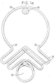
- the basic construction of the attachment link 10 comprises a straddling portion 20 of substantially C-shape from which a pair of legs 30 depends.
- Each leg 30 is provided at its end remote from the straddling portion with a connecting eye 40 through which the connecting portion of a karabiner/hook (not shown) is passed in use.
- the legs 30 of the attachment link are of convoluted form, with hairpin loops 35 interposed between the straddling portion 20 and the connecting eyes 40.
- the legs 30 deform by straightening of the loops 35 so that sudden shock forces are dissipated.
- the sudden shock forces are absorbed in such a way that the falling load experiences a gentle braking force rather than a jolt, so that stresses on the system and on the load are minimised.
- Another advantage of this particular arrangement is that a visible indication is provided that the system has been subjected to loading sufficient to cause deformation of the attachment link. This serves as a clear reminder to would-be users of the system that some of its components may need replacement before it can be utilised safely.
- the eyes 40 of the respective legs 30 are shown in alignment and sufficiently close that they are linkable by a single karabiner/hook.
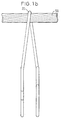
- the eyes 40 are oriented with their common axis parallel to the longitudinal axis of the elongate element 50. This necessitates slightly offsetting the respective legs 30 so that one overlies the other as best seen with reference to Figure 1b.
- FIG 2 views (a) and (b) omit the elongate element 50 and the loops 35 for clarity.
- This attachment link is provided with an array 60 of low friction rings 61 arranged around the arc of its straddling portion.
- the rings 61 may be formed of any suitable low friction material, such as phosphor bronze or plastic. As shown, the rings are held in place over the operating arc of the straddling portion by raised formations such as pimples 62. It is also possible for the straddling portion itself to be provided with a low friction coating, though such an arrangement is not depicted in Figure 2.
- Figure 3 shows an alternative arrangement in which an arrangement of rolling element bearings 70 is mounted on the straddling portion of the attachment link.
- elongate element 50 and loops 35 have been omitted from the views in this Figure for clarity.
- the arrangement shown here is particularly well adapted for minimising the effects of wear on the elongate element, as well as on the attachment link itself, in situations where heavy loads are encountered.
- the attachment link with its bearings must be matched to a suitably-configured elongate element support system which is able to accommodate the bulk of the link in the space formed between the rotating wheel and the cooperating slipper part.
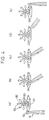
- an attachment link 10 in accordance with the present invention is shown negotiating a support device for an elongate element 50.
- Support devices of this type are described in more detail in the Applicant's European Patent No. 0 124 189.
- the views in Figure 4 omit loops 35 for clarity.
- the attachment link 10 is seen approaching the support device from the left.
- the support device comprises a rotatable wheel 102 provided with a series of recesses 103 at spaced locations around its periphery. Adjacent recesses are separated by projecting parts 104 of the wheel.
- a cooperating slipper part 101 is mounted on the wheel with the aid of formations (not shown) which inter-engage with complementary formations on the projecting parts 104 of the wheel.
- Elongate element 50 is retained in a space formed between the wheel 102 and the slipper part 101.
- attachment link 10 is shown engaging one of the projecting parts 104 of the wheel 102. This engagement causes rotation of the wheel 102 in a counter-clockwise direction as seen in Figure 4.
- Views (c) and (d) show the attachment link 10 captured in one of the recesses 103 of the wheel 102 and riding over the slipper part 101 as the wheel continues its counter-clockwise rotation.
- the attachment link 10 is shown after release from the recess 103, having traversed the support device without detachment from the elongate element 50.
- FIG. 5 views (a) to (c) show an attachment link 10 in accordance with the present invention in a direction looking along the longitudinal axis of an elongate element 50. These views show how the attachment link can be oriented at a wide variety of angles relative to the elongate member whilst still being capable of traversing rotary support devices therefor. Again, loops 35 have been omitted for clarity.
Landscapes
- Engineering & Computer Science (AREA)
- General Engineering & Computer Science (AREA)
- Mechanical Engineering (AREA)
- Health & Medical Sciences (AREA)
- General Health & Medical Sciences (AREA)
- Business, Economics & Management (AREA)
- Emergency Management (AREA)
- Pivots And Pivotal Connections (AREA)
- Emergency Lowering Means (AREA)
- Hooks, Suction Cups, And Attachment By Adhesive Means (AREA)
Description
- Figures 1a and 1b
- show, respectively, front and side views of an attachment link according to the invention;
- Figure 2
- shows simplified front and side views of an attachment link having friction-reducing elements on its straddling portion;
- Figure 3
- shows simplified front and side views of an attachment link provided with rolling-element bearings on its straddling portion;
- Figure 4
- shows the sequence of steps through which the attachment link of the invention passes as it traverses a rotary cable support, and
- Figure 5
- illustrates the suitability of the invention for traversing such supports in a variety of orientations.
Claims (6)
- A link (10) for attaching a load-bearing attachment to an elongate element (50), the link (10) comprising a substantially C-shaped straddling portion (20) having a pair of legs (30) each provided with a connecting eye (40), said legs (30) having a gap therebetween to accommodate an elongate element (50) and said connecting eyes (40) being aligned to receive a portion of a load-bearing attachment, characterised in that each of said legs (30) includes a convoluted portion interposed between the straddling portion (20) and its respective connecting eye (40) in which the material of the leg (30) is bent back upon itself to form a series of hairpin loops (35).
- A link (10) as claimed in claim 1 wherein the legs (30) are deformable by straightening of said loops (35) in response to the application of a predetermined tensile load.
- A link (10) as claimed in claim 1 or claim 2, the arrangement being such that receipt of a load-bearing attachment through the connecting eyes (40) of the link (10) forms a closed loop which prevents disengagement of the link (10) from an elongate element (50) accommodated between said legs (30).
- A link (10) as claimed in any preceding claim wherein low friction means (60, 70) are provided on the straddling portion (20) of the link (10).
- A link (10) as claimed in claim 4 wherein the low friction means comprises a series of rings or beads (60) of low friction material.
- A link (10) as claimed in claim 4 wherein the low friction means comprises one or more rolling element bearings (70).
Applications Claiming Priority (3)
| Application Number | Priority Date | Filing Date | Title |
|---|---|---|---|
| GB9410910A GB9410910D0 (en) | 1994-06-01 | 1994-06-01 | Universal attachment link |
| GB9410910 | 1994-06-01 | ||
| PCT/GB1995/001250 WO1995032759A1 (en) | 1994-06-01 | 1995-05-31 | Universal attachment link |
Publications (2)
| Publication Number | Publication Date |
|---|---|
| EP0762909A1 EP0762909A1 (en) | 1997-03-19 |
| EP0762909B1 true EP0762909B1 (en) | 1998-08-12 |
Family
ID=10755973
Family Applications (1)
| Application Number | Title | Priority Date | Filing Date |
|---|---|---|---|
| EP95919586A Expired - Lifetime EP0762909B1 (en) | 1994-06-01 | 1995-05-31 | Yielding attachment link |
Country Status (7)
| Country | Link |
|---|---|
| EP (1) | EP0762909B1 (en) |
| JP (1) | JPH10500879A (en) |
| AU (1) | AU692552B2 (en) |
| CA (1) | CA2191770A1 (en) |
| DE (1) | DE69504063D1 (en) |
| GB (1) | GB9410910D0 (en) |
| WO (1) | WO1995032759A1 (en) |
Families Citing this family (8)
| Publication number | Priority date | Publication date | Assignee | Title |
|---|---|---|---|---|
| DE29805788U1 (en) | 1998-03-30 | 1998-07-30 | Söll GmbH, 95028 Hof | Fall arrest system |
| EP0996487A1 (en) * | 1998-05-17 | 2000-05-03 | Hans-Detlef Brust | Fall prevention device and auxiliary device for climbing |
| AU2200001A (en) | 1999-12-21 | 2001-07-03 | Keyguard Limited | Energy absorber |
| GB2357563B (en) * | 1999-12-21 | 2002-04-03 | Latchways Plc | Energy absorber |
| GB2370089C (en) | 2000-05-18 | 2002-08-21 | Keyguard Ltd | Energy absorber |
| FR3027641A1 (en) * | 2014-10-24 | 2016-04-29 | Florent Thierry Charles Berthet | DEVICE FOR CONNECTING A SECURITY LENGTH - COMMONLY CALLED LEASH - TO A HIGHLINE (STRAP OF FUNAMBULISM) |
| SE547151C2 (en) * | 2023-04-13 | 2025-05-06 | Cwl Patent Ab | An arrangement for guiding a safety line and an installation comprising one or more structures of a building and comprising one or more arrangements |
| CA222877S (en) | 2023-07-17 | 2024-11-12 | Delta Prevention Inc | Base for a safety rail |
Family Cites Families (6)
| Publication number | Priority date | Publication date | Assignee | Title |
|---|---|---|---|---|
| US1363401A (en) * | 1920-04-26 | 1920-12-28 | Jr John H Flynn | Hook and shackle for pulley-blocks |
| US1407797A (en) * | 1920-12-29 | 1922-02-28 | William H Moore | Snap hook |
| GB183025A (en) * | 1921-06-16 | 1922-07-20 | Herbert Richmond | An improved hook connection for chains, ropes, cables, straps and the like |
| US4470480A (en) * | 1982-04-22 | 1984-09-11 | Celez Remy B | Manually operated conveying apparatus |
| GB8722253D0 (en) * | 1987-09-22 | 1987-10-28 | Tupper A W | Safety attachment systems |
| US5286130A (en) * | 1992-12-22 | 1994-02-15 | Mueller Charles R | Clevis assembly |
-
1994
- 1994-06-01 GB GB9410910A patent/GB9410910D0/en active Pending
-
1995
- 1995-05-31 JP JP8500521A patent/JPH10500879A/en active Pending
- 1995-05-31 WO PCT/GB1995/001250 patent/WO1995032759A1/en not_active Ceased
- 1995-05-31 CA CA002191770A patent/CA2191770A1/en not_active Abandoned
- 1995-05-31 DE DE69504063T patent/DE69504063D1/en not_active Expired - Lifetime
- 1995-05-31 AU AU25361/95A patent/AU692552B2/en not_active Ceased
- 1995-05-31 EP EP95919586A patent/EP0762909B1/en not_active Expired - Lifetime
Also Published As
| Publication number | Publication date |
|---|---|
| DE69504063D1 (en) | 1998-09-17 |
| AU692552B2 (en) | 1998-06-11 |
| WO1995032759A1 (en) | 1995-12-07 |
| JPH10500879A (en) | 1998-01-27 |
| AU2536195A (en) | 1995-12-21 |
| GB9410910D0 (en) | 1994-07-20 |
| EP0762909A1 (en) | 1997-03-19 |
| CA2191770A1 (en) | 1995-12-07 |
Similar Documents
| Publication | Publication Date | Title |
|---|---|---|
| CA2153831C (en) | Horizontal lifeline energy absorber | |
| EP1339460B1 (en) | Supporting bracket assembly for a horizontal lifeline cable | |
| AU692552B2 (en) | Universal attachment link | |
| US6126110A (en) | Horizontally opposed trunnion forward engine mount system supported beneath a wing pylon | |
| US7996964B2 (en) | Buckle device | |
| EP0223964B1 (en) | Improved mechanically expanding climbing aid | |
| CA2063246A1 (en) | Fall-arrest systems | |
| EP3672695B1 (en) | Case or cradle for a fall arrest device | |
| TWI249604B (en) | Friction damper | |
| EP1282460A1 (en) | Energy absorber | |
| CA3126747A1 (en) | Coupler for a fall protection device | |
| GB2451799A (en) | A fall arrest system | |
| CA2489107A1 (en) | Energy absorber for horizontal lifeline system | |
| EP0825939A1 (en) | Seismic pipe restraint and method of using | |
| JP3756979B2 (en) | Girder fall prevention structure | |
| US6334507B1 (en) | Fall protection system and trolley for use in such a system | |
| AU766842B2 (en) | Horizontal lifeline fall arrest system | |
| EP1567229B1 (en) | Safety line traveller and support | |
| EP0677615B1 (en) | Variable configuration road barrier with energy dissipating means | |
| WO1999055425A1 (en) | Height safety systems | |
| EP0309183B1 (en) | Safety attachment systems, and parts and fittings therefor | |
| US5105907A (en) | Fall restraint cable support and method | |
| US20120024640A1 (en) | Energy absorbing device for anchoring a lifeline or the like | |
| US5002152A (en) | Fall restraint cable support and method | |
| US4480149A (en) | Lightweight frame-type elastomer damping spacer |
Legal Events
| Date | Code | Title | Description |
|---|---|---|---|
| PUAI | Public reference made under article 153(3) epc to a published international application that has entered the european phase |
Free format text: ORIGINAL CODE: 0009012 |
|
| 17P | Request for examination filed |
Effective date: 19961011 |
|
| AK | Designated contracting states |
Kind code of ref document: A1 Designated state(s): DE FR GB IT |
|
| GRAG | Despatch of communication of intention to grant |
Free format text: ORIGINAL CODE: EPIDOS AGRA |
|
| 17Q | First examination report despatched |
Effective date: 19970925 |
|
| GRAG | Despatch of communication of intention to grant |
Free format text: ORIGINAL CODE: EPIDOS AGRA |
|
| GRAH | Despatch of communication of intention to grant a patent |
Free format text: ORIGINAL CODE: EPIDOS IGRA |
|
| GRAH | Despatch of communication of intention to grant a patent |
Free format text: ORIGINAL CODE: EPIDOS IGRA |
|
| GRAA | (expected) grant |
Free format text: ORIGINAL CODE: 0009210 |
|
| AK | Designated contracting states |
Kind code of ref document: B1 Designated state(s): DE FR GB IT |
|
| PG25 | Lapsed in a contracting state [announced via postgrant information from national office to epo] |
Ref country code: IT Free format text: LAPSE BECAUSE OF FAILURE TO SUBMIT A TRANSLATION OF THE DESCRIPTION OR TO PAY THE FEE WITHIN THE PRE;WARNING: LAPSES OF ITALIAN PATENTS WITH EFFECTIVE DATE BEFORE 2007 MAY HAVE OCCURRED AT ANY TIME BEFORE 2007. THE CORRECT EFFECTIVE DATE MAY BE DIFFERENT FROM THE ONE RECORDED.SCRIBED TIME-LIMIT Effective date: 19980812 Ref country code: FR Free format text: LAPSE BECAUSE OF FAILURE TO SUBMIT A TRANSLATION OF THE DESCRIPTION OR TO PAY THE FEE WITHIN THE PRESCRIBED TIME-LIMIT Effective date: 19980812 |
|
| REF | Corresponds to: |
Ref document number: 69504063 Country of ref document: DE Date of ref document: 19980917 |
|
| PG25 | Lapsed in a contracting state [announced via postgrant information from national office to epo] |
Ref country code: DE Free format text: LAPSE BECAUSE OF FAILURE TO SUBMIT A TRANSLATION OF THE DESCRIPTION OR TO PAY THE FEE WITHIN THE PRESCRIBED TIME-LIMIT Effective date: 19981113 |
|
| EN | Fr: translation not filed | ||
| PLBE | No opposition filed within time limit |
Free format text: ORIGINAL CODE: 0009261 |
|
| STAA | Information on the status of an ep patent application or granted ep patent |
Free format text: STATUS: NO OPPOSITION FILED WITHIN TIME LIMIT |
|
| 26N | No opposition filed | ||
| REG | Reference to a national code |
Ref country code: GB Ref legal event code: IF02 |
|
| PGFP | Annual fee paid to national office [announced via postgrant information from national office to epo] |
Ref country code: GB Payment date: 20020402 Year of fee payment: 8 |
|
| PG25 | Lapsed in a contracting state [announced via postgrant information from national office to epo] |
Ref country code: GB Free format text: LAPSE BECAUSE OF NON-PAYMENT OF DUE FEES Effective date: 20030531 |
|
| GBPC | Gb: european patent ceased through non-payment of renewal fee |
Effective date: 20030531 |