EP0762842B1 - Display tray - Google Patents
Display tray Download PDFInfo
- Publication number
- EP0762842B1 EP0762842B1 EP95918092A EP95918092A EP0762842B1 EP 0762842 B1 EP0762842 B1 EP 0762842B1 EP 95918092 A EP95918092 A EP 95918092A EP 95918092 A EP95918092 A EP 95918092A EP 0762842 B1 EP0762842 B1 EP 0762842B1
- Authority
- EP
- European Patent Office
- Prior art keywords
- walls
- display device
- writing instruments
- recesses
- profiled
- Prior art date
- Legal status (The legal status is an assumption and is not a legal conclusion. Google has not performed a legal analysis and makes no representation as to the accuracy of the status listed.)
- Expired - Lifetime
Links
- 239000000463 material Substances 0.000 claims description 4
- 239000004800 polyvinyl chloride Substances 0.000 claims description 3
- 229920003052 natural elastomer Polymers 0.000 claims description 2
- 229920001194 natural rubber Polymers 0.000 claims description 2
- 229920003051 synthetic elastomer Polymers 0.000 claims description 2
- 239000005061 synthetic rubber Substances 0.000 claims description 2
- 229920002725 thermoplastic elastomer Polymers 0.000 claims description 2
- 244000043261 Hevea brasiliensis Species 0.000 claims 1
- 230000000694 effects Effects 0.000 description 4
- 239000004033 plastic Substances 0.000 description 2
- 229920003023 plastic Polymers 0.000 description 2
- 238000000151 deposition Methods 0.000 description 1
- 239000002184 metal Substances 0.000 description 1
- 239000004575 stone Substances 0.000 description 1
- 239000002023 wood Substances 0.000 description 1
Images



Classifications
-
- B—PERFORMING OPERATIONS; TRANSPORTING
- B43—WRITING OR DRAWING IMPLEMENTS; BUREAU ACCESSORIES
- B43M—BUREAU ACCESSORIES NOT OTHERWISE PROVIDED FOR
- B43M99/00—Subject matter not provided for in other groups of this subclass
- B43M99/001—Desk sets
- B43M99/002—Tubular fountain pen holders
- B43M99/006—Tubular fountain pen holders with more than one penholder
-
- A—HUMAN NECESSITIES
- A47—FURNITURE; DOMESTIC ARTICLES OR APPLIANCES; COFFEE MILLS; SPICE MILLS; SUCTION CLEANERS IN GENERAL
- A47F—SPECIAL FURNITURE, FITTINGS, OR ACCESSORIES FOR SHOPS, STOREHOUSES, BARS, RESTAURANTS OR THE LIKE; PAYING COUNTERS
- A47F7/00—Show stands, hangers, or shelves, adapted for particular articles or materials
- A47F7/0021—Show stands, hangers, or shelves, adapted for particular articles or materials for long or non-stable articles, e.g. fishing rods, pencils, lipsticks or the like; Compartments or recesses as stabilising means
- A47F7/0028—Show stands, hangers, or shelves, adapted for particular articles or materials for long or non-stable articles, e.g. fishing rods, pencils, lipsticks or the like; Compartments or recesses as stabilising means with one compartment or recess for each article
Definitions
- the present invention relates to a display device.
- Display devices for writing instruments by means of which the writing instruments can be displayed in a shop for viewing by prospective purchasers, are often made of vacuum-formed recessed frays.
- the writing instruments we simply put into shallow elongate recesses in the trays which we often keep in drawers in a display cabinet in a shop. If a customer wishes to view the writing instruments, the trays will be moved as they we retrieved from the cabinet and presented to the customer. This can lead to damage of the surfaces of the writing instruments since they can slide about in the trays as the drawers in which the frays we stored are opened and closed and also when the trays are passed to the customer. In addition, these recessed trays we generally unattractive and have little scope for varying the display effect.
- DE-C-900668 discloses a device for depositing and supporting drawing pencils, the device having a planar upper surface, the upper surface having outstanding walls each wall having a profiled edge for supporting the pencils. Similar devices are disclosed in US-A-4182455 and CH-A-341404. None of these references however disclose supporting walls that are removable or suggest such walls.
- a display device having a generally planar upper surface, the upper surface having at least two upstanding walls, each wall having a profiled edge for receiving and supporting a generally cylindrical object characterized by at least one of the walls being removable from the upper surface.
- the display device for displaying writing instruments in particular.
- the device can be used for displaying other generally cylindrical objects.
- the writing instruments can be laid across the upstanding walls to be supported by the walls.
- the profiled edges of the walls preferably include a plurality of recesses, each recess being for receiving a cylindrical object.
- each recess being for receiving a cylindrical object.
- At least one of the walls is removable from the upper surface.
- Said at least one removable wall may be an elongate trip which is profiled on each of its opposed long edges.
- the profiles on the opposed long edges may differ from one another. This enables further variation in the display effect since a different pitch between adjacent writing instruments or other objects can be achieved according to which long edge is uppermost.
- the arrangement is such that a cylindrical object is supported by the walls so as not to contact the upper surface.
- This has two main advantages. Firstly, the object is held away from the surface and is thus protected from damage by contact with the upper surface. Secondly, since the object is held out of contact with the surface, any display background can be used, thus allowing greater scope in the display effect which may be achieved.
- the walls are preferably made of a material with a relatively high coefficient of friction. This prevents the objects from sliding around on the display device.
- the walls may be made of polyvinylchloride (PVC).
- a display device 1 has a generally rectangular or square base 2 in the form of a tile.
- the base 2 has a pair of parallel elongate grooves 3, 4 in its upper surface 5.
- the elongate grooves 3, 4 extend across the base and divide the upper surface 5 into three roughly equal portions.
- a pair of elongate strips 6, 7 have a thickness which is substantially equal to the thickness of the respective grooves 3, 4 so that the strips 6, 7 can be snugly received in the respective grooves 3, 4 to form two upstanding walls.
- Each strip 6, 7 has an upper long edge 8 and a lower long edge 9. At least the upper edge 8, and preferably also the lower edge 9, of each strip 6, 7 is profiled.
- the profiling is in the form of a sawtooth which defines a plurality of triangular recesses 10 along the upper edge 8 of the strip 6, 7.
- the triangular recesses 10 can easily accommodate relatively large diameter writing instruments 11 or relatively small diameter writing instruments 12 or intermediate size writing instruments 13.
- each profiling providing recesses 10 which can receive writing instruments, which may be of different sizes as in Figure 8.
- Both the upper and lower edges 8, 9 of the strips 6, 7 may be profiled.
- the profiling on the respective upper and lower edges 8, 9 may be different as shown in Figure 9.
- the pitch between adjacent recesses 10 may differ between the upper and lower edges 8, 9 to provide different spacing between adjacent writing instruments 11 or other objects displayed on the device 1.
- the recesses 10 may be relatively deeper on the lower edge 9 compared to the upper edge 8 of the strips 6, 7 to accommodate a greater range of size of writing instruments 11.
- the strips 6, 7 are preferably made of a material having a relatively high coefficient of friction, such as polyvinylchloride (PVC), a thermoplastic elastomer, or natural or synthetic rubber, so that the writing instruments 11 are gripped firmly and are less prone to sliding off the strips 6 when the device 1 is moved.
- PVC polyvinylchloride
- thermoplastic elastomer or natural or synthetic rubber
- a supporting ridge 14 may be provided along one edge of the base 2 parallel to the strips 6, 7, the supporting ridge 14 standing proud of the upper surface 5. This provides a backstop against which the writing instruments 11 may rest.
- the recesses 10 of the strip 6 furthest away from this supporting ridge 14 may be relatively higher than the strip 7 which is relatively nearer the ridge 14 so that the writing instruments 11 are inclined slightly backwards to the ridge 14.
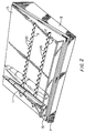
- FIG. 2 A second example of a display device is shown in Figures 2 and 3.
- the base 2 is wedge-shaped as shown so that the writing instruments 11 tilt backwards.
- a clear plastics wall 15 is provided as the backstop to support the rear of the writing instruments 11.
- the writing instruments 11 are shown generally parallel to the side edges of the base 2.
- the writing instruments 11 may alternatively be fanned across the device 1 as shown in Figure 3. This may be achieved by using one strip 6 in which the recesses are spaced having a relatively small pitch and a second strip 7 in which the recesses 10 have a relatively greater pitch, the writing instruments 11 then being placed in adjacent recesses 10.
- the upper part of each writing instrument 11 can simply be placed in alternate recesses 10 in one of the strips 7 where the two strips 6, 7 have the same or substantially the same spacing between recesses 10.
- the writing instruments 11 are supported by the strips 6 so as not to contact the upper surface 5, simply by arranging that the lower portions of the recesses 10 are sufficiently clear of the upper surface 5.
- any material can be used for the upper surface 5.
- the upper surface 5 may be made of wood, metal, stone, plastics, etc.
- the upper surface 5 may be detachably clipped to the base 2 so that different display backgrounds for the upper surface 5 can be used interchangeably.
- the undersurface of the base 2 may have recesses or protuberances which enable it to be stacked on top of other tiles or some other support. This enables adjacent display devices 1 to be displayed at different heights in a showcase, which enhances the attractiveness of the overall display.
Landscapes
- Drawing Aids And Blackboards (AREA)
- Mirrors, Picture Frames, Photograph Stands, And Related Fastening Devices (AREA)
Description
- The present invention relates to a display device.
- Display devices for writing instruments, by means of which the writing instruments can be displayed in a shop for viewing by prospective purchasers, are often made of vacuum-formed recessed frays. The writing instruments we simply put into shallow elongate recesses in the trays which we often keep in drawers in a display cabinet in a shop. If a customer wishes to view the writing instruments, the trays will be moved as they we retrieved from the cabinet and presented to the customer. This can lead to damage of the surfaces of the writing instruments since they can slide about in the trays as the drawers in which the frays we stored are opened and closed and also when the trays are passed to the customer. In addition, these recessed trays we generally unattractive and have little scope for varying the display effect.
- DE-C-900668 discloses a device for depositing and supporting drawing pencils, the device having a planar upper surface, the upper surface having outstanding walls each wall having a profiled edge for supporting the pencils. Similar devices are disclosed in US-A-4182455 and CH-A-341404. None of these references however disclose supporting walls that are removable or suggest such walls.
- According to the present invention, there is provided a display device having a generally planar upper surface, the upper surface having at least two upstanding walls, each wall having a profiled edge for receiving and supporting a generally cylindrical object characterized by at least one of the walls being removable from the upper surface.
- In this specification, reference will be made to the display device for displaying writing instruments in particular. However, it is to be understood that the device can be used for displaying other generally cylindrical objects.
- The writing instruments can be laid across the upstanding walls to be supported by the walls.
- The profiled edges of the walls preferably include a plurality of recesses, each recess being for receiving a cylindrical object. By providing a plurality of recesses, the writing instruments or other objects can be laid across the two walls generally at a right angle to the length of the walls, or at some other angle. This enables some flexibility in the display, for example, allowing the writing instruments or other objects to be fanned out across the display device.
- At least one of the walls is removable from the upper surface. Said at least one removable wall may be an elongate trip which is profiled on each of its opposed long edges. The profiles on the opposed long edges may differ from one another. This enables further variation in the display effect since a different pitch between adjacent writing instruments or other objects can be achieved according to which long edge is uppermost.
- Preferably, the arrangement is such that a cylindrical object is supported by the walls so as not to contact the upper surface. This has two main advantages. Firstly, the object is held away from the surface and is thus protected from damage by contact with the upper surface. Secondly, since the object is held out of contact with the surface, any display background can be used, thus allowing greater scope in the display effect which may be achieved.
- The walls are preferably made of a material with a relatively high coefficient of friction. This prevents the objects from sliding around on the display device. For example, the walls may be made of polyvinylchloride (PVC).
- An example of the present invention will be described with reference to the accompanying drawings, in which:
- Fig. 1 is a perspective view of a firsi example of a display device;
- Fig. 2 is a perspective view of a second example of a display device;
- Fig. 3 is a perspective view of the display device of Fig. 2 with writing instruments in a "fanned" orientation;
- Figs. 4 to 7 are partial elevations of walls and cross-sections through the display device showing examples of profiles of the walls;
- Fig. 8 shows writing instruments of different sizes being supported by a wall; and,
- Fig. 9 is an elevation of a wall having different profiles on its upper and lower edges.
-
- A display device 1 has a generally rectangular or
square base 2 in the form of a tile. Thebase 2 has a pair of parallelelongate grooves 3, 4 in itsupper surface 5. Theelongate grooves 3, 4 extend across the base and divide theupper surface 5 into three roughly equal portions. - A pair of elongate strips 6, 7 have a thickness which is substantially equal to the thickness of the
respective grooves 3, 4 so that the strips 6, 7 can be snugly received in therespective grooves 3, 4 to form two upstanding walls. - Each strip 6, 7 has an upper
long edge 8 and a lowerlong edge 9. At least theupper edge 8, and preferably also thelower edge 9, of each strip 6, 7 is profiled. In the example shown in Figure 1 and Figure 7, the profiling is in the form of a sawtooth which defines a plurality oftriangular recesses 10 along theupper edge 8 of the strip 6, 7. As can be seen in Figure 8, thetriangular recesses 10 can easily accommodate relatively largediameter writing instruments 11 or relatively smalldiameter writing instruments 12 or intermediatesize writing instruments 13. - Examples of different profiles for the strip 6, 7 are shown in Figures 4 to 6, each
profiling providing recesses 10 which can receive writing instruments, which may be of different sizes as in Figure 8. - Both the upper and
lower edges lower edges adjacent recesses 10 may differ between the upper andlower edges adjacent writing instruments 11 or other objects displayed on the device 1. Alternatively or additionally, therecesses 10 may be relatively deeper on thelower edge 9 compared to theupper edge 8 of the strips 6, 7 to accommodate a greater range of size ofwriting instruments 11. - The strips 6, 7 are preferably made of a material having a relatively high coefficient of friction, such as polyvinylchloride (PVC), a thermoplastic elastomer, or natural or synthetic rubber, so that the
writing instruments 11 are gripped firmly and are less prone to sliding off the strips 6 when the device 1 is moved. - A supporting
ridge 14 may be provided along one edge of thebase 2 parallel to the strips 6, 7, the supportingridge 14 standing proud of theupper surface 5. This provides a backstop against which thewriting instruments 11 may rest. Therecesses 10 of the strip 6 furthest away from this supportingridge 14 may be relatively higher than the strip 7 which is relatively nearer theridge 14 so that thewriting instruments 11 are inclined slightly backwards to theridge 14. - A second example of a display device is shown in Figures 2 and 3. In this example, the
base 2 is wedge-shaped as shown so that thewriting instruments 11 tilt backwards. Also, instead of theridge 14 of the example of Figure 1, aclear plastics wall 15 is provided as the backstop to support the rear of thewriting instruments 11. - In Figures 1 and 2, the
writing instruments 11 are shown generally parallel to the side edges of thebase 2. Thewriting instruments 11 may alternatively be fanned across the device 1 as shown in Figure 3. This may be achieved by using one strip 6 in which the recesses are spaced having a relatively small pitch and a second strip 7 in which therecesses 10 have a relatively greater pitch, thewriting instruments 11 then being placed inadjacent recesses 10. Alternatively, as shown, the upper part of eachwriting instrument 11 can simply be placed inalternate recesses 10 in one of the strips 7 where the two strips 6, 7 have the same or substantially the same spacing betweenrecesses 10. - It will be seen that the
writing instruments 11 are supported by the strips 6 so as not to contact theupper surface 5, simply by arranging that the lower portions of therecesses 10 are sufficiently clear of theupper surface 5. This means that any material can be used for theupper surface 5. This in turn means that there is no restriction on the background which may be applied to theupper surface 5, thus giving free choice to the display effect to be achieved. For example, theupper surface 5 may be made of wood, metal, stone, plastics, etc. Theupper surface 5 may be detachably clipped to thebase 2 so that different display backgrounds for theupper surface 5 can be used interchangeably. - It will be appreciated that more than two walls 6 may be used if required, though for supporting writing instruments, it is believed that two walls 6, 7 would be sufficient.
- The undersurface of the
base 2 may have recesses or protuberances which enable it to be stacked on top of other tiles or some other support. This enables adjacent display devices 1 to be displayed at different heights in a showcase, which enhances the attractiveness of the overall display.
Claims (7)
- A display device (1) having a generally planar upper surface (5), the upper surface having at least two upstanding walls (6, 7) each wall having a profiled edge (8, 9) for receiving and supporting a generally cylindrical object (11) characterized by at least one of the walls (6, 7) being removable from the upper surface (5).
- A display device according to claim 1, wherein the profiled edges of the walls include a plurality of recesses (8, 10) each recess being for receiving a cylindrical object.
- A display device according to claim 1, wherein said at least one removable wall is an elongate strip which is profiled on each of its opposed long edges.
- A display device according to claim 3, wherein the profiles on the opposed long edges differ from one another.
- A display device according to claim 1, wherein the cylindrical object is supported by the walls (6, 7) so as not to contact the upper surface (5).
- A display device according to claim 1, wherein the walls (6, 7) are made of a material with a relatively high coefficient of friction.
- A display device according to claim 6, wherein the walls are made of polyvinylchloride (PVC), a thermoplastic elastomer, natural rubber or synthetic rubber.
Applications Claiming Priority (3)
| Application Number | Priority Date | Filing Date | Title |
|---|---|---|---|
| GB9409532 | 1994-05-12 | ||
| GB9409532A GB9409532D0 (en) | 1994-05-12 | 1994-05-12 | Display device |
| PCT/GB1995/001071 WO1995031126A1 (en) | 1994-05-12 | 1995-05-11 | Display tray |
Publications (2)
| Publication Number | Publication Date |
|---|---|
| EP0762842A1 EP0762842A1 (en) | 1997-03-19 |
| EP0762842B1 true EP0762842B1 (en) | 2000-07-19 |
Family
ID=10755030
Family Applications (1)
| Application Number | Title | Priority Date | Filing Date |
|---|---|---|---|
| EP95918092A Expired - Lifetime EP0762842B1 (en) | 1994-05-12 | 1995-05-11 | Display tray |
Country Status (6)
| Country | Link |
|---|---|
| US (1) | US5938040A (en) |
| EP (1) | EP0762842B1 (en) |
| JP (1) | JPH10500329A (en) |
| DE (1) | DE69518076T2 (en) |
| GB (1) | GB9409532D0 (en) |
| WO (1) | WO1995031126A1 (en) |
Families Citing this family (11)
| Publication number | Priority date | Publication date | Assignee | Title |
|---|---|---|---|---|
| FR2794350B1 (en) * | 1999-06-04 | 2001-10-19 | Jacques Lambert | DEVICE FOR PRESENTING AND TRANSPORTING OYSTERS |
| US20030014186A1 (en) * | 2000-11-15 | 2003-01-16 | International Business Machines Corporation | Apparatus, system, and method for determining a user position and progress along a path |
| US20030214207A1 (en) * | 2002-05-16 | 2003-11-20 | Baier Goetz Ekkehard | Extension, in particular, a drawer |
| US20170232442A1 (en) * | 2007-03-12 | 2017-08-17 | New Objective, Inc. | Packaging, shipping and storage device for capillary tubes |
| USD694561S1 (en) * | 2012-02-20 | 2013-12-03 | Bulthaup Gmbh & Co. Kg | Kitchen drawer accessory |
| USD694050S1 (en) * | 2012-07-04 | 2013-11-26 | Bulthaup Gmbh & Co. Kg | Kitchen drawer accessory |
| USD694051S1 (en) * | 2012-08-09 | 2013-11-26 | Bulthaup Gmbh & Co. Kg | Kitchen drawer accessory |
| US11517660B2 (en) * | 2017-08-01 | 2022-12-06 | Blanca Nasker | Syringe organizer |
| US10334969B1 (en) | 2018-04-30 | 2019-07-02 | Art Guild, Inc. | Modular display |
| US11072198B1 (en) * | 2021-01-19 | 2021-07-27 | Vitalii Savryha | Modular paper organizer |
| US11701916B2 (en) * | 2021-09-02 | 2023-07-18 | Jeremiah A. Zambrotta | Mason jar-mounted paint brush holder |
Family Cites Families (18)
| Publication number | Priority date | Publication date | Assignee | Title |
|---|---|---|---|---|
| US565710A (en) * | 1896-08-11 | Pen and pencil case | ||
| US539720A (en) * | 1895-05-21 | Bottle-case | ||
| US531799A (en) * | 1895-01-01 | Common-school writing-cabinet | ||
| US662824A (en) * | 1900-05-08 | 1900-11-27 | Frederick Howard Rosher | Advertising-rack. |
| US952593A (en) * | 1909-09-10 | 1910-03-22 | Gustave H Wagner | Pen-rack. |
| US1360042A (en) * | 1920-04-12 | 1920-11-23 | Srofe Jesse | Box-blank |
| FR1030005A (en) * | 1950-12-21 | 1953-06-09 | Device for the presentation of artificial teeth and other articles | |
| US2649191A (en) * | 1951-03-19 | 1953-08-18 | Frank H Mclaughlin | Automobile tool kit |
| DE900668C (en) * | 1951-12-29 | 1953-12-28 | Georg Schweitzer | Filing and carrying device for writing and drawing pens with an organizing catcher |
| CH341404A (en) * | 1957-12-11 | 1959-09-30 | Caran D Ache Crayons | Packaging for a series of pencils |
| US3554429A (en) * | 1968-12-16 | 1971-01-12 | Shell Containers Inc | Container with partition supporting means |
| US3837477A (en) * | 1972-01-31 | 1974-09-24 | D Boudreau | Drawer arranger |
| US4182455A (en) * | 1977-11-16 | 1980-01-08 | Adams Brush Mfg. Co., Inc. | Container rack |
| GB2033740A (en) * | 1978-10-11 | 1980-05-29 | Andra Jewels Ltd | Display board |
| US4341308A (en) * | 1980-07-18 | 1982-07-27 | Pasquini William G | Container for bottles |
| US4705168A (en) * | 1982-07-21 | 1987-11-10 | Southern Case, Inc. | Drawer divider system |
| US5215726A (en) * | 1991-07-17 | 1993-06-01 | Hu-Friedy Mfg. Co., Inc. | Two-tiered sterilization and storage cassette |
| US5505316A (en) * | 1994-07-29 | 1996-04-09 | Kwi Jun Enterprise Limited | Adjustable wrench-rack |
-
1994
- 1994-05-12 GB GB9409532A patent/GB9409532D0/en active Pending
-
1995
- 1995-05-11 JP JP7529438A patent/JPH10500329A/en active Pending
- 1995-05-11 DE DE69518076T patent/DE69518076T2/en not_active Expired - Fee Related
- 1995-05-11 WO PCT/GB1995/001071 patent/WO1995031126A1/en not_active Ceased
- 1995-05-11 US US08/737,391 patent/US5938040A/en not_active Expired - Fee Related
- 1995-05-11 EP EP95918092A patent/EP0762842B1/en not_active Expired - Lifetime
Also Published As
| Publication number | Publication date |
|---|---|
| JPH10500329A (en) | 1998-01-13 |
| DE69518076D1 (en) | 2000-08-24 |
| GB9409532D0 (en) | 1994-06-29 |
| EP0762842A1 (en) | 1997-03-19 |
| US5938040A (en) | 1999-08-17 |
| WO1995031126A1 (en) | 1995-11-23 |
| DE69518076T2 (en) | 2001-03-22 |
Similar Documents
| Publication | Publication Date | Title |
|---|---|---|
| US5938040A (en) | Display tray | |
| US5638963A (en) | Product management apparatus and method | |
| US5289925A (en) | Organizational display for compact disc jewel boxes | |
| US5803276A (en) | Adjustable shelf divider | |
| US6006927A (en) | Paint chip display system | |
| US8136677B2 (en) | Adjustable greeting card pocket | |
| US6213313B1 (en) | Paint chip display system | |
| GB2281289A (en) | A display shelf/case divider system | |
| CA2096387C (en) | Rack for newspapers | |
| US5253767A (en) | Rotatable display tower for compact discs and the like | |
| US6003687A (en) | Compact disc storage rack | |
| US7913862B2 (en) | Display tray with movable dividers | |
| US4611720A (en) | Display rack system for candles | |
| EP1018744A2 (en) | Assemblable storage and display unit | |
| US4538736A (en) | Marker storage cassette and holders therefor | |
| US5316138A (en) | Carpet display sample kit | |
| US4261124A (en) | Album cover display frame | |
| US7516853B1 (en) | Auxiliary shelf system | |
| US6932212B2 (en) | Unitary molded clip for jewelry | |
| US4492307A (en) | Leaflet dispenser | |
| US11072198B1 (en) | Modular paper organizer | |
| US12329277B2 (en) | Divided desktop organizer | |
| US20100108547A1 (en) | Storage Device | |
| US5409108A (en) | Cartridge/cassette storage apparatus | |
| US20210204725A1 (en) | Adhesive Surface Divider |
Legal Events
| Date | Code | Title | Description |
|---|---|---|---|
| PUAI | Public reference made under article 153(3) epc to a published international application that has entered the european phase |
Free format text: ORIGINAL CODE: 0009012 |
|
| 17P | Request for examination filed |
Effective date: 19961212 |
|
| AK | Designated contracting states |
Kind code of ref document: A1 Designated state(s): DE FR GB |
|
| RBV | Designated contracting states (corrected) |
Designated state(s): DE FR GB |
|
| 17Q | First examination report despatched |
Effective date: 19980529 |
|
| GRAG | Despatch of communication of intention to grant |
Free format text: ORIGINAL CODE: EPIDOS AGRA |
|
| GRAG | Despatch of communication of intention to grant |
Free format text: ORIGINAL CODE: EPIDOS AGRA |
|
| GRAH | Despatch of communication of intention to grant a patent |
Free format text: ORIGINAL CODE: EPIDOS IGRA |
|
| GRAH | Despatch of communication of intention to grant a patent |
Free format text: ORIGINAL CODE: EPIDOS IGRA |
|
| GRAA | (expected) grant |
Free format text: ORIGINAL CODE: 0009210 |
|
| AK | Designated contracting states |
Kind code of ref document: B1 Designated state(s): DE FR GB |
|
| REF | Corresponds to: |
Ref document number: 69518076 Country of ref document: DE Date of ref document: 20000824 |
|
| ET | Fr: translation filed | ||
| PGFP | Annual fee paid to national office [announced via postgrant information from national office to epo] |
Ref country code: FR Payment date: 20010503 Year of fee payment: 7 |
|
| PGFP | Annual fee paid to national office [announced via postgrant information from national office to epo] |
Ref country code: DE Payment date: 20010508 Year of fee payment: 7 |
|
| PGFP | Annual fee paid to national office [announced via postgrant information from national office to epo] |
Ref country code: GB Payment date: 20010509 Year of fee payment: 7 |
|
| PLBE | No opposition filed within time limit |
Free format text: ORIGINAL CODE: 0009261 |
|
| STAA | Information on the status of an ep patent application or granted ep patent |
Free format text: STATUS: NO OPPOSITION FILED WITHIN TIME LIMIT |
|
| 26N | No opposition filed | ||
| REG | Reference to a national code |
Ref country code: GB Ref legal event code: IF02 |
|
| PG25 | Lapsed in a contracting state [announced via postgrant information from national office to epo] |
Ref country code: GB Free format text: LAPSE BECAUSE OF NON-PAYMENT OF DUE FEES Effective date: 20020511 |
|
| PG25 | Lapsed in a contracting state [announced via postgrant information from national office to epo] |
Ref country code: DE Free format text: LAPSE BECAUSE OF NON-PAYMENT OF DUE FEES Effective date: 20021203 |
|
| GBPC | Gb: european patent ceased through non-payment of renewal fee |
Effective date: 20020511 |
|
| PG25 | Lapsed in a contracting state [announced via postgrant information from national office to epo] |
Ref country code: FR Free format text: LAPSE BECAUSE OF NON-PAYMENT OF DUE FEES Effective date: 20030131 |
|
| REG | Reference to a national code |
Ref country code: FR Ref legal event code: ST |