EP0762840B1 - Wrist rest assembly - Google Patents
Wrist rest assembly Download PDFInfo
- Publication number
- EP0762840B1 EP0762840B1 EP95916465A EP95916465A EP0762840B1 EP 0762840 B1 EP0762840 B1 EP 0762840B1 EP 95916465 A EP95916465 A EP 95916465A EP 95916465 A EP95916465 A EP 95916465A EP 0762840 B1 EP0762840 B1 EP 0762840B1
- Authority
- EP
- European Patent Office
- Prior art keywords
- pad
- supported
- layer
- elongate
- base
- Prior art date
- Legal status (The legal status is an assumption and is not a legal conclusion. Google has not performed a legal analysis and makes no representation as to the accuracy of the status listed.)
- Expired - Lifetime
Links
Images


Classifications
-
- G—PHYSICS
- G06—COMPUTING; CALCULATING OR COUNTING
- G06F—ELECTRIC DIGITAL DATA PROCESSING
- G06F3/00—Input arrangements for transferring data to be processed into a form capable of being handled by the computer; Output arrangements for transferring data from processing unit to output unit, e.g. interface arrangements
- G06F3/01—Input arrangements or combined input and output arrangements for interaction between user and computer
- G06F3/03—Arrangements for converting the position or the displacement of a member into a coded form
- G06F3/033—Pointing devices displaced or positioned by the user, e.g. mice, trackballs, pens or joysticks; Accessories therefor
- G06F3/039—Accessories therefor, e.g. mouse pads
- G06F3/0395—Mouse pads
-
- A—HUMAN NECESSITIES
- A47—FURNITURE; DOMESTIC ARTICLES OR APPLIANCES; COFFEE MILLS; SPICE MILLS; SUCTION CLEANERS IN GENERAL
- A47B—TABLES; DESKS; OFFICE FURNITURE; CABINETS; DRAWERS; GENERAL DETAILS OF FURNITURE
- A47B21/00—Tables or desks for office equipment, e.g. typewriters, keyboards
- A47B21/03—Tables or desks for office equipment, e.g. typewriters, keyboards with substantially horizontally extensible or adjustable parts other than drawers, e.g. leaves
- A47B21/0371—Platforms for supporting wrists
- A47B2021/0378—Platforms for supporting wrists filled with liquid or gel
-
- A—HUMAN NECESSITIES
- A47—FURNITURE; DOMESTIC ARTICLES OR APPLIANCES; COFFEE MILLS; SPICE MILLS; SUCTION CLEANERS IN GENERAL
- A47B—TABLES; DESKS; OFFICE FURNITURE; CABINETS; DRAWERS; GENERAL DETAILS OF FURNITURE
- A47B21/00—Tables or desks for office equipment, e.g. typewriters, keyboards
- A47B21/03—Tables or desks for office equipment, e.g. typewriters, keyboards with substantially horizontally extensible or adjustable parts other than drawers, e.g. leaves
- A47B21/0371—Platforms for supporting wrists
- A47B2021/0392—Platforms for supporting wrists height adjustable
-
- A—HUMAN NECESSITIES
- A47—FURNITURE; DOMESTIC ARTICLES OR APPLIANCES; COFFEE MILLS; SPICE MILLS; SUCTION CLEANERS IN GENERAL
- A47B—TABLES; DESKS; OFFICE FURNITURE; CABINETS; DRAWERS; GENERAL DETAILS OF FURNITURE
- A47B2200/00—General construction of tables or desks
- A47B2200/0084—Accessories for tables or desks
- A47B2200/009—Keyboards associated with mousepads
-
- A—HUMAN NECESSITIES
- A47—FURNITURE; DOMESTIC ARTICLES OR APPLIANCES; COFFEE MILLS; SPICE MILLS; SUCTION CLEANERS IN GENERAL
- A47B—TABLES; DESKS; OFFICE FURNITURE; CABINETS; DRAWERS; GENERAL DETAILS OF FURNITURE
- A47B2200/00—General construction of tables or desks
- A47B2200/0084—Accessories for tables or desks
- A47B2200/0093—Wrist pad cover
-
- H—ELECTRICITY
- H01—ELECTRIC ELEMENTS
- H01H—ELECTRIC SWITCHES; RELAYS; SELECTORS; EMERGENCY PROTECTIVE DEVICES
- H01H2217/00—Facilitation of operation; Human engineering
- H01H2217/034—Support for hands or arms
-
- Y—GENERAL TAGGING OF NEW TECHNOLOGICAL DEVELOPMENTS; GENERAL TAGGING OF CROSS-SECTIONAL TECHNOLOGIES SPANNING OVER SEVERAL SECTIONS OF THE IPC; TECHNICAL SUBJECTS COVERED BY FORMER USPC CROSS-REFERENCE ART COLLECTIONS [XRACs] AND DIGESTS
- Y10—TECHNICAL SUBJECTS COVERED BY FORMER USPC
- Y10S—TECHNICAL SUBJECTS COVERED BY FORMER USPC CROSS-REFERENCE ART COLLECTIONS [XRACs] AND DIGESTS
- Y10S248/00—Supports
- Y10S248/917—Video display screen support
- Y10S248/918—Ancillary device support associated with a video display screen
Definitions
- the present invention relates to wrist rest assemblies for use along the front edges of devices to be operated by a person's hands or fingers, such as in front of a computer keyboard, computer mouse or other input device, as basically known from US-A-5,163,646.
- Wrist rest assemblies are known for use along the front edge of a device to be operated by a person's hands or fingers, such as in front of a computer key board, computer mouse or other input device. It has been suggested that the use of such wrist rest assemblies can restrict damage to wrists from prolonged use of such devices.
- the wrist rest assembly for use along the front edge of a device to be operated by a person's hands or fingers, such as in front of a computer keyboard.
- the wrist rest assembly comprises a base having an upper surface and an opposite bottom supported surface adapted to be supported on a horizontal surface along the front edge of the device, and a pad comprising a layer of liquid (water).
- the pad has opposite top and bottom surfaces, opposite longitudinally extending edges, and opposite longitudinally spaced ends, the bottom surface of said elongate pad being supported on the upper surface of said base.
- the pad has a sufficient thickness between said top and bottom surfaces and width between said edges to afford supporting a users wrist on said top surface.
- the present invention provides a wrist rest assembly for use along the front edge of a device to be operated by a person's hands or fingers, such as in front of a computer key board, computer mouse or other input device, which wrist rest assembly provides a layer of cushioning material that can provide better support for the wrists than has heretofore been provided, and further affords a degree of movement of the supported wrist relative to the surface on which the wrist rest is supported that has not been provided by known prior art wrist rest assemblies.
- a wrist rest assembly comprising (1) a base having an upper pad support surface, which base has a bottom or supported surface adapted to be supported on a horizontal surface along the front edge of the device; and (2) a pad comprising a layer of stable elastomeric block polymer gel.
- a bottom surface of the elongate pad is supported on the upper pad support surface of the base, and the pad has a sufficient width between its edges and thickness between its top and bottom surfaces (e.g., a thickness in the range of about 0,3175 cm to 12,7 cm (1/8 inch to 5 inches) and a width in the range of about 1,27 cm to 25.4 cm (1/2 to 10 inches) with the larger widths providing both wrist and fore arm support) to afford supporting a users wrists on the top surface to help keep the wrists in a neutral position with a portion of the layer of gel beneath and conforming to the supported wrists to distribute the weight of the wrists over a wide area and affording significant motion of the top surface of the pad with the supported wrists relative to the bottom surface in a plane generally parallel to the upper surface of the base.
- a sufficient width between its edges and thickness between its top and bottom surfaces e.g., a thickness in the range of about 0,3175 cm to 12,7 cm (1/8 inch to 5 inches) and a width in the range of about 1,27 cm
- the stable elastomeric block polymer gel is similar to the gel described in US-A-3,676,387, and preferably is the gel described in Example No. 3 of GB-A-1,268,431 (the content whereof is hereby incorporated herein by reference) except that the ratio of oil to block copolymer is in the range of 4 to 1 to 10 to 1 rather than being 5 to 1 as is described in that Example No. 3.
- That gel is quite similar to the gel in the pad commercially available from Minnesota Mining and Manufacturing Company, St. Paul, Minnesota, under the trade designation "Reston (T.M.) Flotation Pad", which pad for many years has been used in beds, wheel chairs and the like to prevent pressure points.
- the gel has a covering comprising an elongate tubular layer of flexible polymeric material (e.g., polyurethane) around the gel, which tubular layer has sealed ends to retain the gel and provides a flexible barrier to the escape of mineral oil from within the gel.
- the pad assembly can further include an outer layer over the top surface of the pad of a soft conformable material adapted for comfortable contact with a users wrists.
- the base comprises a top portion having the upper pad support surface supporting the bottom surface of the elongate pad; a bottom portion having the bottom supported surface adapted to be supported on a horizontal surface; and means for supporting the top portion on the bottom portion with the elongate pad at a predetermined one of several different distances above the supported surface.
- top portion of the base comprising longitudinally extending rails projecting outwardly in opposite directions generally parallel to its upper pad support surface, and the bottom portion including generally parallel spaced vertically upwardly projecting support portions having opposed surfaces defining sets of grooves parallel to the supported surface and vertically spaced along the support portions, each of which sets of grooves is adapted to receive the rails to support the top portion with the top surface of the elongate pad at a different distance above the supported surface depending on which set of grooves the rails are engaged in.
- the assembly includes means for releasably fixing the top portion relative to the bottom portion with corresponding ends of the top and bottom portions generally in alignment.
- the method according to the present invention for supporting the wrists of a person operating a device comprises: (1) providing a pad comprising a layer of gel, which pad has opposite top and bottom surfaces, and opposite longitudinally extending edges; (2) supporting the pad along the front edge of the device; and (3) supporting the users wrists along the top surface of pad; the pad having a sufficient thickness between the top and bottom surfaces and width between the edges to have a portion of the layer of gel beneath and conforming to the supported wrists and to afford significant motion of the top surface of the pad with the supported wrists relative to the bottom surface in a horizontal plane.
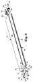
- the wrist rest assembly 10 is adapted for use along the front edge of a device to be operated by a person's hands or fingers, such as in front of a computer keyboard 11 as is illustrated in Figure 7 or in front of a computer mouse 12 as is illustrated in Figure 8 with a shortened version 10a thereof, or in front of a computer keyboard 11 and mouse 12 as is illustrated in Figure 9 with an extended version 10b thereof, to provide support for the wrists of a person using the keyboard 11 and/or mouse 12.
- the wrist rest assembly 10 comprises (1) an elongate base 14 having an elongate upper pad support surface 15 (see Figure 6), which base 14 has a bottom supported surface 16 generally parallel to its upper pad support surface 15 adapted to be supported on a horizontal surface along the front edge of the device 11 or 12; and (2) an elongate pad 17 comprising a covering 18 and a layer of gel 19 within the covering 18.
- the pad 17, which is shown separated from the base 14 in Figure 1, has opposite top and bottom surfaces 20 and 21, opposite longitudinally extending edges 22, and opposite ends 24.
- the bottom surface 21 of the elongate pad 17 is supported on and can be adhered to the upper pad support surface 15 of the base 14, and the pad 17 has a sufficient thickness between its top and bottom surfaces 20 and 21 and sufficient width between its edges 22 to afford supporting a users wrists along its top surface 20 with a portion of the layer of gel 19 beneath and conforming to the supported wrists and affording significant motion of the top surface 20 of the pad with the supported wrists relative to its bottom surface 21 in a plane generally parallel to the upper surface 15 of the base 14.
- the gel 19 is that gel described in Example No. 3 in 1,268,431 except that the ratio of oil to block copolymer is 6 to 1 rather than being 5 to 1 as is described in that Example No.
- the layer of that gel 19 has a thickness of about 0,9525 cm (3/8 inch) and a width between the edges of the pad 17 of about 7,366 cm (2.9 inches); and the covering 18 is of 0,00508 cm (0.002 inch) thick polyurethane; that motion of the top surface 20 of the pad with a supported wrist relative to its bottom surface 21 in a plane generally parallel to the supported surface 16 of the base 14 allows the supported wrist and the users hand to move in any direction in a generally circular area having a diameter of about 2,54 cm (one inch).
- the area of such movement could be made larger or smaller by using different gel compositions, but for most embodiments of the wrist rest should be a circular area having a diameter of at least 1,27 cm (1/2 inch).
- FIGS 1 through 4 sequentially illustrate the assembly of the wrist rest assembly 10 and certain details about its structure.
- the covering 18 of the pad 17, best seen in Figure 1 is an elongate tubular layer of a flexible polymeric material (e.g. 2,54 x 10 -3 cm to 7,62 x 10 -3 cm (0.001 to 0.003 inch) thick polyurethane) around the gel 19 which is sealed at the ends 24 of the pad 17 (e.g., by heat sealing) to retain the gel 19 within the tubular layer and provide a flexible barrier to the escape of mineral oil or other liquids from within the gel 19.
- a flexible polymeric material e.g. 2,54 x 10 -3 cm to 7,62 x 10 -3 cm (0.001 to 0.003 inch) thick polyurethane
- the assembly 10 further includes an outer layer 26 over the top surface 20 of the pad 17 adapted for comfortable contact with a users wrists.
- That outer layer 26 can, for example, be made of a soft conformable non-woven polyurethane material, or of other materials such as leather, vinyl, or the material commercially designated “Dacron” (T.M.) sold by DuPont, Wilmington, Delaware, or the material commercially designated “Ultrilure” (R.T.M.).
- the base 14 includes an elongate support plate 28 (e.g., an extrusion of rigid polyvinyl chloride or polystyrene) including a generally plate-like top portion 29 having opposite sides 30, opposite ends 31, the generally planer upper pad support surface 15, and an opposite bottom surface 33.
- the support plate 28 also includes plate like side portions 34 along the opposite sides of the top portion 29 and extending away from the bottom surface 33 of the top portion 29 to form with the top portion 29 an elongate recess 36.
- the pad 17 is supported along the upper pad support surface 15 of the support plate 28; and the outer layer 26 is in the form of a elongate sleeve having opposite end portions 38 and extends around the elongate support plate 28 and the elongate pad 17 (see Figure 2) with its end portions 38 extending past their ends.
- the base 14 further includes an elongate retaining member 40 (e.g., also an extrusion of rigid polyvinyl chloride or polystyrene) comprising a tensioning portion 42 within and extending along the elongate recess 36 with a portion of the outer layer 26 between the tensioning portion 42 and the support plate 28 (see Figure 6) to tension the outer layer 26 across the top surface 20 of the pad 17.
- an elongate retaining member 40 e.g., also an extrusion of rigid polyvinyl chloride or polystyrene
- Means in the form of a layer of adhesive impregnating and on both sides of the outer layer 26, or ultrasonic welding, or screws, or rivets, or pins, or a friction fit between the tensioning portion 42 and the support plate 28 are provided for retaining the tensioning portion 42 within the elongate recess 36.
- Means are also provided for retaining the end portions 38 of the sleeve or outer layer 26 around the ends 24 of the pad 17 (see Figure 3).
- the retaining member 40 has opposite ends 44 at the ends 24 of the pad 17 and openings 46 into those ends 44.
- the end portions 38 of the sleeve of outer layer 26 that extend beyond the ends 24 of the pad 17 are positioned in the openings 46.
- the assembly 10 includes end caps 48 attached at the opposite ends 44 of the retaining member 40 by two self taping screws 50 extending through the end caps 48 and engaging openings 51 in the retaining member 40.
- the end caps 48 include projections 52 projecting into the openings 46 in the retaining member 40 that engage the end portions 38 of the outer layer 26 sleeve to provide the means for retaining those end portions 38 around the ends 24 of the pad 17.
- the base 14 also includes a bottom portion 56 having the bottom supported surface 16 adapted to be supported on a horizontal surface; and, as is best seen in Figure 4 and 6, means are provided for supporting the top portion 54 on the bottom portion 56 with the top surface 20 of the elongate pad 17 at a desired predetermined one of several different distances above the bottom surface 16.
- the top portion 54 of the base 14 comprises longitudinally extending rails 58 on the retaining member 40 projecting outwardly in opposite directions generally parallel to its upper surface 15; and the bottom portion 56 of the base 14 includes generally parallel spaced vertically upwardly projecting support portions 59 having opposed surfaces defining sets of horizontal grooves 60a, 60b and 60c vertically spaced along the support portions 59.
- Each of the sets of grooves 60a, 60b or 60c is adapted to slidably receive the rails 58 to support the top surface 20 of the pad 17 on the top portion 54 at a different distance above the bottom supported surface 16.
- the top portion 54 of the base 14 can be slid longitudinally of its bottom portion 56 to disengage the rails 58 from one set of the grooves 60a, 60b or 60c with which they are engaged, and subsequently engaged with a different set of the grooves 60a, 60b or 60c to change the distance between the supported surface 16 and the top surface 20 of the pad as may be desirable to properly support a users wrists.
- the top and bottom portions 54 and 56 are both of about the same length, and the assembly 10 further includes means for releasably retaining the top portion 54 in the bottom portion 56 with the corresponding ends of the top and bottom portions 54 and 56 generally in alignment. That means comprises removable end covers 62 each adapted for engagement with an end of the top portion 54 and extending across and around the adjacent end of the bottom portion 56 so that the end of the top portion 54 with which the end cover 62 is engaged can not move further into the bottom portion 56.
- each end cover 62 and an end of the top portion 54 Engagement between each end cover 62 and an end of the top portion 54 is provided in that the end caps 48 have opposite outwardly projecting vertically extending tabs 64 (Figure 3) at their ends adjacent the support portions 59, and the end covers 62 have opposed inwardly projecting vertically extending tabs 66 ( Figure 5) adapted to engage between the tabs 64 on the end caps 48 and the ends 44 of the retaining member 40 when the end cover 62 is slid vertically toward the supported surface 16 to the position illustrated in Figure 5.
- the top portion 54 cannot move in the bottom portion 56 in either direction, and thus is releasably retained in the bottom portion 56 with the corresponding ends of the top and bottom portions 54 and 56 generally in alignment.
- the top portion 54 can reciprocate along the bottom portion 56 by sliding movement of the rails 58 in the surfaces defining the grooves 60a, 60b or 60c with which they are engaged which affords removing the top portion 54 from the bottom portion 56 and re-engaging it with the rails 58 in a different set of grooves 60a, 60b or 60c to change the distance between the top surface 20 of the pad and the supported surface 16.
- Such reciprocation afforded by removing one or both of the end covers 62 might also provide advantages for some uses of the assembly 10 to affording large transverse movements of the wrists with the top portion 54 without relocating the wrists along the top surface 20 of the pad 17 (e.g., to move one hand from the typing keys to the numerical pad of a computer keyboard without lifting the wrists from the pad 17).
- the wrist rest assembly can be made any length;
- the pad support surface of the base could have shapes other than generally planar such as being arcuate around a longitudinal axis to make it, for example, cylindrically convex or concave, or could have transverse recesses below where a users wrists would normally be supported;
- the bottom portion 56 of the base could have more or less than three sets of grooves to provide larger or smaller ranges of adjustment;
- the wrist rest assembly could further include a base plate attached along and having a portion projecting from the supported surface 16 of base, which projecting portion is adapted to support the device, such as those base plates 70, 71 or 72 illustrated in Figures 7, 8 and 9.
Landscapes
- Engineering & Computer Science (AREA)
- General Engineering & Computer Science (AREA)
- Theoretical Computer Science (AREA)
- Human Computer Interaction (AREA)
- Physics & Mathematics (AREA)
- General Physics & Mathematics (AREA)
- Input From Keyboards Or The Like (AREA)
Abstract
Description
Claims (11)
- A wrist rest assembly (10) for use along the front edge of a device to be operated by a person's hands or fingers, such as in front of a computer keyboard, computer mouse or other input device, said wrist rest assembly (10) comprising:a base (14) having an upper surface and an opposite bottom supported surface (16) adapted to be supported on a horizontal surface along the front edge of the device; anda pad (17) having opposite top and bottom surfaces (20, 21), opposite longitudinally extending edges, and opposite longitudinally spaced ends, the bottom surface (21) of said elongate pad (17) being supported on the upper surface of said base (14), said pad (17) having a sufficient thickness between said top and bottom surfaces (20, 21) and width between said edges to afford supporting a users wrists on said top surface (20);said wrist rest assembly (10) being characterized by the feature that said pad (17) comprises a layer (19) of stable elastomeric block polymer gel adapted to conform to wrists being supported by a portion of the layer (19) of gel and to afford significant motion of the top surface (20) of the pad (17) with the supported wrists relative to the bottom surface (21) in a plane parallel to said surfaces (20, 21).
- A wrist rest assembly (10) according to claim 1 further characterized in that said pad (17) comprises an elongate tubular layer (18) of flexible polymeric material around the layer (19) of gel, said tubular layer (18) being sealed at said ends of said pad (17) to retain the layer (19) of gel within the tubular inner layer (18) and to provide a flexible barrier to the escape of liquids from within the layer (19) of gel.
- A wrist rest assembly (10) according to claim 1 further characterized in that said assembly includes an outer layer (26) over the top surface of the pad (17) of soft conformable material adapted for comfortable contact with a users wrists.
- A wrist rest assembly (10) according to claim 1 further characterized in that said pad (17) comprises an elongate tubular layer (18) of flexible polymeric material around the gel, said tubular layer (18) being sealed at said ends of said pad (17) to retain the layer (19) of gel within the tubular inner layer (18) and to provide a flexible barrier to the escape of liquids from within the layer (19) of gel; and said assembly further includes an outer layer (26) over the top surface of the pad (17) of soft conformable material adapted for comfortable contact with a users wrists.
- A wrist rest assembly (10) according to claim 4 further characterized in thatsaid base (14) includes an elongate support plate (28) including a generally planar top portion (29) having opposite sides (30), opposite ends (31), a generally planer top surface (15) and an opposite bottom surface (33), and side portions (34) along the opposite sides of said top portion (29) and extending away from the bottom surface (33) of said top portion (29) to form with said top portion (29) an elongate recess (36);said bottom surface of said pad (17) is supported along the top surface (15) of said support plate (28);said outer layer (19) is in the form of a sleeve having opposite end portions extending around said elongate support plate (28) and the said pad (17); andsaid base (14) further includes an elongate retaining member (40) comprising a tensioning portion (42) within and extending along said elongate recess (36) with a portion of said outer layer (26) between said tensioning portion (42) and said support plate (28) to tension said outer layer (26) across said top surface of said pad (17), means for retaining said tensioning portion (42) within said elongate recess (36), and means for retaining the end portions of said sleeve (26) around the ends of said pad (17).
- A wrist rest assembly (10) according to claim 5 further characterized in that said retaining member (40) has opposite ends (44) at the ends of said elongate pad (17) and openings (46) into said ends (44), the end portions (38) of said sleeve (26) are positioned in said openings (46), and said assembly includes end caps (48) attached at the opposite ends (44) of said retaining member (40) and including projections (52) projecting into said openings (46) in said retaining member (40) to provide said means for retaining the end portions (38) of said sleeve (26) around the ends of the pad (17).
- A wrist rest assembly (10) according to claim 1 further characterized in that said base (14) comprises a top portion (54) having said upper surface (15) supporting the bottom surface (21) of said elongate pad (17); a bottom portion (56) having said bottom surface (16) adapted to be supported on a horizontal surface; and means for supporting said top portion (54) on said bottom portion (56) with the top surface (20) of said elongate pad (17) at a predetermined one of several different distances above said bottom surface (16).
- A wrist rest assembly (10) according to claim 1 further characterized in that said pad (17) is in the range of about 1/8 inch to 5 inches thick between said top and bottom surfaces (20, 21) and said top surface (20) is in the range of about 1/2 inch to 10 inches wide between said edges.
- A wrist rest assembly (10) according to claim 1 further characterized in that the motion of said top surface (20) of said pad (17) with a supported wrist relative to said bottom surface (21) in a plane generally parallel to the supported surface of the base (14) allows that wrist to move in any direction in a generally circular area having a diameter of at least one half inch.
- A wrist rest assembly (10) according to claim 1 further characterized in that the motion of said top surface (20) of said pad (17) with a supported wrist relative to said bottom surface (21) in a plane generally parallel to the supported surface (16) of the base (14) allows that wrist to move in any direction in a generally circular area having a diameter of about one inch.
- A wrist rest assembly (10) according to claim 1 further including a base plate (70, 71, 72) attached along and having a portion projecting from the supported surface (16) of said base (14), said projecting portion (70, 71, 72) of said base (14) plate being adapted to support the device.
Priority Applications (1)
| Application Number | Priority Date | Filing Date | Title |
|---|---|---|---|
| DE29521531U DE29521531U1 (en) | 1994-06-03 | 1995-04-21 | Wrist support assembly |
Applications Claiming Priority (3)
| Application Number | Priority Date | Filing Date | Title |
|---|---|---|---|
| US25351094A | 1994-06-03 | 1994-06-03 | |
| US253510 | 1994-06-03 | ||
| PCT/US1995/004877 WO1995033394A1 (en) | 1994-06-03 | 1995-04-21 | Wrist rest assembly |
Publications (2)
| Publication Number | Publication Date |
|---|---|
| EP0762840A1 EP0762840A1 (en) | 1997-03-19 |
| EP0762840B1 true EP0762840B1 (en) | 1998-09-16 |
Family
ID=22960577
Family Applications (1)
| Application Number | Title | Priority Date | Filing Date |
|---|---|---|---|
| EP95916465A Expired - Lifetime EP0762840B1 (en) | 1994-06-03 | 1995-04-21 | Wrist rest assembly |
Country Status (6)
| Country | Link |
|---|---|
| US (1) | US5713544A (en) |
| EP (1) | EP0762840B1 (en) |
| JP (2) | JP3898756B2 (en) |
| CA (1) | CA2189133C (en) |
| DE (1) | DE69504833T2 (en) |
| WO (1) | WO1995033394A1 (en) |
Families Citing this family (32)
| Publication number | Priority date | Publication date | Assignee | Title |
|---|---|---|---|---|
| US5730403A (en) * | 1995-10-26 | 1998-03-24 | Johnson; Mark C. | Arched panel wrist support |
| US5980143A (en) * | 1996-08-28 | 1999-11-09 | Minnesota Mining And Manufacturing Company | Wrist rest assembly |
| SE509792C2 (en) * | 1996-11-26 | 1999-03-08 | Bohman Information I Hudiksval | Keyboard holder device |
| US5813777A (en) * | 1997-05-09 | 1998-09-29 | Bonnstauffer; Bill | Stress relieving keys |
| AUPP029497A0 (en) * | 1997-11-11 | 1997-12-04 | Clement, Anthony James | Wrist support |
| CA2240068A1 (en) * | 1998-07-17 | 2000-01-17 | Donald L. Corbett | The wristthotic chariot |
| US6390423B1 (en) | 1998-12-04 | 2002-05-21 | Fellowes, Inc. | Ergonomic soft-feel mouse |
| US6089516A (en) * | 1998-12-11 | 2000-07-18 | Yates; Paul M. | Decorative cushion providing wide lateral movement support |
| US6413609B1 (en) * | 1999-04-08 | 2002-07-02 | Paul M. Yates | Elastomer film laminated cushion |
| US6219867B1 (en) | 1999-04-08 | 2001-04-24 | Paul M. Yates | Cushion pad with enhanced conformability |
| US6133556A (en) * | 1999-04-19 | 2000-10-17 | Ramsey; Douglas P. | Heated deformable support |
| US6216988B1 (en) * | 1999-06-24 | 2001-04-17 | International Business Machines Corporation | Integrated wrist rest |
| US6903924B1 (en) | 1999-12-17 | 2005-06-07 | Jeff D. Tyner | Computer keyboard tray |
| US6644605B1 (en) | 1999-12-17 | 2003-11-11 | Cnd Development, Inc. | Computer keyboard tray |
| TW454890U (en) * | 2000-01-26 | 2001-09-11 | Jou Jian Fa | Computer wrist pad with adjustable height and hardness |
| US6488244B2 (en) * | 2001-02-08 | 2002-12-03 | Ying Gang Ruan | Typing support |
| US20030187378A1 (en) * | 2002-04-02 | 2003-10-02 | Gaylord Robert Scott | Medical padding product with adjustable and removable gel pad |
| US6694553B1 (en) | 2002-08-21 | 2004-02-24 | Paul M. Yates | Baseless cushion |
| EP1393651A1 (en) * | 2002-09-02 | 2004-03-03 | Octogone GmbH | Wrist support |
| US20050115475A1 (en) * | 2003-12-02 | 2005-06-02 | Sheng-Hsiung Lin | Keyboard carrier |
| US6932304B1 (en) * | 2004-02-27 | 2005-08-23 | Joseph Villamar | Wrist support device |
| US7157633B1 (en) | 2004-03-02 | 2007-01-02 | Richard Martin Kopesec | Simulated stringed instrument practice device |
| US6981735B1 (en) | 2005-03-08 | 2006-01-03 | Aaron Stephens | Apparatus for interior auto comfort pads |
| US8541496B2 (en) | 2005-12-29 | 2013-09-24 | Joel Sereboff | Energy absorbing composition and impact and sound absorbing applications thereof |
| US8987367B2 (en) | 2005-12-29 | 2015-03-24 | Joel L. Sereboff | Energy absorbing composition and impact and sound absorbing applications thereof |
| WO2007079230A2 (en) * | 2005-12-29 | 2007-07-12 | Joel Sereboff | Energy absorbing composition and impact and sound absorbing applications thereof |
| GB0708481D0 (en) * | 2007-05-02 | 2007-06-06 | Pro Stance Ltd | Weight distribution determination apparatus |
| US8439160B2 (en) | 2010-11-09 | 2013-05-14 | California Institute Of Technology | Acoustic suppression systems and related methods |
| US10517393B2 (en) * | 2017-09-18 | 2019-12-31 | Noel Webb | Pad for supporting a user's wrists, lower arms, and keyboard while typing |
| USD1014511S1 (en) * | 2021-11-11 | 2024-02-13 | Lg Electronics Inc. | Mouse pad for computer |
| USD999773S1 (en) * | 2021-11-29 | 2023-09-26 | Logitech Europe S.A. | Palm rest |
| USD1002639S1 (en) * | 2021-12-21 | 2023-10-24 | HumanCentric Ventures LLC | Wrist rest |
Family Cites Families (23)
| Publication number | Priority date | Publication date | Assignee | Title |
|---|---|---|---|---|
| US793756A (en) * | 1905-03-03 | 1905-07-04 | William W Williams | Pneumatic arm-rest for bookkeepers or writers. |
| US2694026A (en) * | 1951-08-14 | 1954-11-09 | Merle J Johnson | Typewriter pad |
| US2720660A (en) * | 1951-12-07 | 1955-10-18 | Homer H Smith | Pillow construction |
| DE1903406C3 (en) * | 1968-01-29 | 1979-10-31 | Minnesota Mining And Manufacturing Co., Saint Paul, Minn. (V.St.A.) | Highly elastic polymer gel |
| US3676387A (en) * | 1970-12-21 | 1972-07-11 | Minnesota Mining & Mfg | Stable elastomeric polymer-oil combinations |
| US5262468A (en) * | 1977-03-17 | 1993-11-16 | Applied Elastomerics, Inc. | Thermoplastic elastomer gelatinous compositions |
| US4482064A (en) * | 1980-04-04 | 1984-11-13 | Joseph J. Berke | Computer terminal support and hand rest |
| US4481556A (en) * | 1980-04-04 | 1984-11-06 | Joseph J. Berke | Computer terminal support and hand rest |
| US4482063A (en) * | 1980-04-04 | 1984-11-13 | Joseph J. Berke | Computer terminal support and hand rest |
| JPS57125069A (en) * | 1980-12-19 | 1982-08-04 | Int Standard Electric Corp | Key board device |
| US4545554A (en) * | 1981-08-31 | 1985-10-08 | Latino Richard M | Wrist support for use with an office machine having a keyboard |
| US4592528A (en) * | 1984-05-22 | 1986-06-03 | Northern Telecom Limited | Leg assembly for a keyboard or the like |
| US4621781A (en) * | 1985-05-16 | 1986-11-11 | Marvel Metal Products Co. | Ergonomic forearm rest for use with keyboards |
| SE459313B (en) * | 1985-12-06 | 1989-06-26 | Kurt Stenvall | SELF-EFFICIENT RELAXING POVERTY |
| CA1282451C (en) * | 1986-08-26 | 1991-04-02 | Lawrie Mcintosh | Retractable work station |
| US4973176A (en) * | 1988-12-20 | 1990-11-27 | Dietrich Jeffrey A | Appendage rest |
| US5163646A (en) * | 1990-09-18 | 1992-11-17 | Bernard Engelhardt | Wrist support arrangement for use with stand-alone keyboard |
| US5131614A (en) * | 1990-10-01 | 1992-07-21 | Garcia James M | Wrist rest support for a computer user |
| US5228655A (en) * | 1990-10-01 | 1993-07-20 | Garcia James M | Wrist rest support for a computer user |
| US5183230A (en) * | 1990-12-12 | 1993-02-02 | Fox Bay Industries, Inc. | Computer keyboard support with padded wrist support |
| US5219136A (en) * | 1991-09-04 | 1993-06-15 | Microcomputer Accessories, Inc. | Adjustable keyboard support |
| US5242139A (en) * | 1992-03-05 | 1993-09-07 | Aldrich Steven H | Keyboard support |
| US5356099A (en) * | 1993-06-28 | 1994-10-18 | Sereboff Joel L | Wrist support system |
-
1995
- 1995-04-21 DE DE69504833T patent/DE69504833T2/en not_active Expired - Lifetime
- 1995-04-21 CA CA002189133A patent/CA2189133C/en not_active Expired - Lifetime
- 1995-04-21 JP JP50084596A patent/JP3898756B2/en not_active Expired - Lifetime
- 1995-04-21 EP EP95916465A patent/EP0762840B1/en not_active Expired - Lifetime
- 1995-04-21 WO PCT/US1995/004877 patent/WO1995033394A1/en active IP Right Grant
-
1996
- 1996-02-06 US US08/597,323 patent/US5713544A/en not_active Expired - Lifetime
-
2006
- 2006-08-23 JP JP2006226729A patent/JP2006313575A/en active Pending
Also Published As
| Publication number | Publication date |
|---|---|
| CA2189133A1 (en) | 1995-12-14 |
| DE69504833T2 (en) | 1999-05-12 |
| DE69504833D1 (en) | 1998-10-22 |
| JP3898756B2 (en) | 2007-03-28 |
| EP0762840A1 (en) | 1997-03-19 |
| WO1995033394A1 (en) | 1995-12-14 |
| CA2189133C (en) | 2002-12-17 |
| JPH10501353A (en) | 1998-02-03 |
| US5713544A (en) | 1998-02-03 |
| JP2006313575A (en) | 2006-11-16 |
Similar Documents
| Publication | Publication Date | Title |
|---|---|---|
| EP0762840B1 (en) | Wrist rest assembly | |
| AU688594B2 (en) | Wrist rest assembly | |
| US20040035986A1 (en) | Wrist rest assembly | |
| EP0923328B1 (en) | Wrist rest assembly | |
| US5125606A (en) | Wrist support for computer keyboard | |
| EP0109841B1 (en) | Mattress for supporting the human body | |
| US5165630A (en) | Wrist protector | |
| US5628483A (en) | Wrist rest | |
| EP0557439A1 (en) | Free sliding hand rest | |
| US5342005A (en) | Arm support apparatus for keyboard and other apparatus requiring repetitive hand operation | |
| US5954303A (en) | Adjustable wrist rest support and method | |
| US5108094A (en) | Comfort cushion for floors | |
| US6131862A (en) | Ergonomic support system | |
| US6017006A (en) | Keyboard wrist rest | |
| US20050092871A1 (en) | Wrist rest assembly | |
| US5765795A (en) | Deformable computer mouse pad | |
| WO2000057749A1 (en) | Wrist support | |
| KR970064346A (en) | Pallets, shifters, and how to move pallets | |
| EP0884692A1 (en) | Mouse mat | |
| WO1998016170A2 (en) | Wrist rest | |
| WO1998016170A9 (en) | Wrist rest | |
| GB2365332A (en) | Cushioned bath tap cover | |
| WO2002069772A1 (en) | Safety devices |
Legal Events
| Date | Code | Title | Description |
|---|---|---|---|
| PUAI | Public reference made under article 153(3) epc to a published international application that has entered the european phase |
Free format text: ORIGINAL CODE: 0009012 |
|
| 17P | Request for examination filed |
Effective date: 19961022 |
|
| AK | Designated contracting states |
Kind code of ref document: A1 Designated state(s): DE FR GB IT NL |
|
| GRAG | Despatch of communication of intention to grant |
Free format text: ORIGINAL CODE: EPIDOS AGRA |
|
| GRAG | Despatch of communication of intention to grant |
Free format text: ORIGINAL CODE: EPIDOS AGRA |
|
| GRAH | Despatch of communication of intention to grant a patent |
Free format text: ORIGINAL CODE: EPIDOS IGRA |
|
| 17Q | First examination report despatched |
Effective date: 19980129 |
|
| GRAH | Despatch of communication of intention to grant a patent |
Free format text: ORIGINAL CODE: EPIDOS IGRA |
|
| GRAA | (expected) grant |
Free format text: ORIGINAL CODE: 0009210 |
|
| AK | Designated contracting states |
Kind code of ref document: B1 Designated state(s): DE FR GB IT NL |
|
| REF | Corresponds to: |
Ref document number: 69504833 Country of ref document: DE Date of ref document: 19981022 |
|
| ET | Fr: translation filed | ||
| PLBE | No opposition filed within time limit |
Free format text: ORIGINAL CODE: 0009261 |
|
| STAA | Information on the status of an ep patent application or granted ep patent |
Free format text: STATUS: NO OPPOSITION FILED WITHIN TIME LIMIT |
|
| 26N | No opposition filed | ||
| REG | Reference to a national code |
Ref country code: GB Ref legal event code: IF02 |
|
| PGFP | Annual fee paid to national office [announced via postgrant information from national office to epo] |
Ref country code: GB Payment date: 20140416 Year of fee payment: 20 |
|
| PGFP | Annual fee paid to national office [announced via postgrant information from national office to epo] |
Ref country code: FR Payment date: 20140409 Year of fee payment: 20 Ref country code: DE Payment date: 20140430 Year of fee payment: 20 Ref country code: NL Payment date: 20140410 Year of fee payment: 20 Ref country code: IT Payment date: 20140221 Year of fee payment: 20 |
|
| REG | Reference to a national code |
Ref country code: DE Ref legal event code: R071 Ref document number: 69504833 Country of ref document: DE |
|
| REG | Reference to a national code |
Ref country code: DE Ref legal event code: R071 Ref document number: 69504833 Country of ref document: DE |
|
| REG | Reference to a national code |
Ref country code: NL Ref legal event code: V4 Effective date: 20150421 |
|
| REG | Reference to a national code |
Ref country code: GB Ref legal event code: PE20 Expiry date: 20150420 |
|
| PG25 | Lapsed in a contracting state [announced via postgrant information from national office to epo] |
Ref country code: GB Free format text: LAPSE BECAUSE OF EXPIRATION OF PROTECTION Effective date: 20150420 |