EP0762694A1 - Local Asynchronous Transfer Mode (ATM) network with at least two ring systems - Google Patents
Local Asynchronous Transfer Mode (ATM) network with at least two ring systems Download PDFInfo
- Publication number
- EP0762694A1 EP0762694A1 EP96202367A EP96202367A EP0762694A1 EP 0762694 A1 EP0762694 A1 EP 0762694A1 EP 96202367 A EP96202367 A EP 96202367A EP 96202367 A EP96202367 A EP 96202367A EP 0762694 A1 EP0762694 A1 EP 0762694A1
- Authority
- EP
- European Patent Office
- Prior art keywords
- network
- ring
- ring system
- connection
- network interface
- Prior art date
- Legal status (The legal status is an assumption and is not a legal conclusion. Google has not performed a legal analysis and makes no representation as to the accuracy of the status listed.)
- Withdrawn
Links
- 238000012546 transfer Methods 0.000 title claims abstract description 14
- 230000005540 biological transmission Effects 0.000 claims abstract description 8
- 230000008878 coupling Effects 0.000 claims description 31
- 238000010168 coupling process Methods 0.000 claims description 31
- 238000005859 coupling reaction Methods 0.000 claims description 31
- 238000000034 method Methods 0.000 claims description 4
- 230000015654 memory Effects 0.000 description 30
- 239000011159 matrix material Substances 0.000 description 13
- 238000012545 processing Methods 0.000 description 3
- 230000002950 deficient Effects 0.000 description 2
- 230000006870 function Effects 0.000 description 2
- 238000009795 derivation Methods 0.000 description 1
- 238000001514 detection method Methods 0.000 description 1
- 238000011161 development Methods 0.000 description 1
- 230000005236 sound signal Effects 0.000 description 1
- 238000013519 translation Methods 0.000 description 1
Images

Classifications
-
- H—ELECTRICITY
- H04—ELECTRIC COMMUNICATION TECHNIQUE
- H04Q—SELECTING
- H04Q11/00—Selecting arrangements for multiplex systems
- H04Q11/04—Selecting arrangements for multiplex systems for time-division multiplexing
- H04Q11/0428—Integrated services digital network, i.e. systems for transmission of different types of digitised signals, e.g. speech, data, telecentral, television signals
- H04Q11/0478—Provisions for broadband connections
-
- H—ELECTRICITY
- H04—ELECTRIC COMMUNICATION TECHNIQUE
- H04L—TRANSMISSION OF DIGITAL INFORMATION, e.g. TELEGRAPHIC COMMUNICATION
- H04L12/00—Data switching networks
- H04L12/28—Data switching networks characterised by path configuration, e.g. LAN [Local Area Networks] or WAN [Wide Area Networks]
- H04L12/46—Interconnection of networks
- H04L12/4604—LAN interconnection over a backbone network, e.g. Internet, Frame Relay
- H04L12/4608—LAN interconnection over ATM networks
-
- H—ELECTRICITY
- H04—ELECTRIC COMMUNICATION TECHNIQUE
- H04L—TRANSMISSION OF DIGITAL INFORMATION, e.g. TELEGRAPHIC COMMUNICATION
- H04L12/00—Data switching networks
- H04L12/28—Data switching networks characterised by path configuration, e.g. LAN [Local Area Networks] or WAN [Wide Area Networks]
- H04L12/46—Interconnection of networks
- H04L12/4637—Interconnected ring systems
-
- H—ELECTRICITY
- H04—ELECTRIC COMMUNICATION TECHNIQUE
- H04J—MULTIPLEX COMMUNICATION
- H04J2203/00—Aspects of optical multiplex systems other than those covered by H04J14/05 and H04J14/07
- H04J2203/0001—Provisions for broadband connections in integrated services digital network using frames of the Optical Transport Network [OTN] or using synchronous transfer mode [STM], e.g. SONET, SDH
- H04J2203/0057—Operations, administration and maintenance [OAM]
- H04J2203/006—Fault tolerance and recovery
-
- H—ELECTRICITY
- H04—ELECTRIC COMMUNICATION TECHNIQUE
- H04L—TRANSMISSION OF DIGITAL INFORMATION, e.g. TELEGRAPHIC COMMUNICATION
- H04L12/00—Data switching networks
- H04L12/54—Store-and-forward switching systems
- H04L12/56—Packet switching systems
- H04L12/5601—Transfer mode dependent, e.g. ATM
- H04L2012/5603—Access techniques
- H04L2012/5609—Topology
- H04L2012/5612—Ring
Definitions
- the invention relates to a local network operating according to the asynchronous transfer mode (ATM) for the transmission of cells with several network interfaces.
- ATM asynchronous transfer mode
- a local area network which operates according to the asynchronous transfer mode is known from EP 0 641 105 A2.
- This network contains several stations and assigned network interfaces, each of which has a send and receive ring connection. Cells that contain address information about the destination, for example of a particular station, are transmitted via the ring formed in this way.
- a network interface contains a coupling device and a control arrangement.
- the coupling device contains a path storage arrangement which is assigned to the receiving ring connection and a path storage arrangement which is assigned to a receiving station connection.
- the corresponding switching or coupling operations are carried out in the coupling device when a cell is received. For example, an incoming cell is forwarded to the control arrangement, the station and / or the ring on the basis of the address information.
- a fixed length block is a cell that has a predetermined number of bytes (eg 53 bytes).
- Each cell consists of a header field with a length of, for example, 5 bytes and an information field in which the useful information is housed, with a length of 48 bytes, for example.
- Address information, data for error detection and data for control information are present in such a header field.
- Address information includes bundle identifiers and connection identifiers.
- the connection identifier which is also referred to as VCI (Virtual Channel Identifier), contains the information about the destination of the cell in the system.
- a virtual channel is made available based on the connection identifier.
- a VCI is changed after reaching an exchange.
- a bundle of several virtual channels is called a virtual path.
- a virtual path is identified by the bundle identifier.
- Such a virtual path is called VPI (Virtual Path Identifier).
- Cells are sequentially assigned to certain time periods. The duration of such a time period depends on the underlying clock frequency of the transmission component. If no useful information is available, empty cells are transmitted in such a time period, ie cells without useful information. Cells that contain useful information are referred to as useful cells.
- the local network known from EP 0 641 105 A2 consists of only one ring system and does not specify any possibilities for exchanging cells over several ring systems.
- a ring system can have one ring or two rings for countercurrent cell currents.
- a ring represents a closed signal path across several network interfaces.
- DE 40 02 022 A1 discloses a method and an arrangement for the highly available transmission of data between two bus systems operating according to the token passing principle.
- the two bus systems are connected to one another via two coupling links provided for the exchange of data.
- One coupling link is active and the other coupling link is in stand-by mode.
- the coupling link in stand-by mode checks the correct token transfer of the active coupling link. With the failure of the active coupling link, the coupling link previously operating in stand-by mode is activated. Thus, only one coupling link is active in this arrangement.
- the object of the invention is therefore to create a local network which operates according to the asynchronous transfer mode and in which an exchange of cells between ring systems is also possible.
- the invention is achieved by a local network operating according to the asynchronous transfer mode of the type mentioned in the introduction in that at least two ring systems are provided, each with two network interfaces, each having at least one bridge connection, and in that a first network interface of a first ring system and a first network interface of a second ring system via at least a first bridge connection for transmitting the cell current between the two ring systems and a second network interface of the first ring system and a second network interface of the second ring system are coupled via at least a second bridge connection for conducting the cell current between the two ring systems.
- the local network according to the invention contains at least two ring systems with one or two rings. Cells can be transferred from one ring system to the other ring system via first network interfaces. The first two network interfaces are coupled to one another via at least one bridge connection. The first and second ring systems each also contain second network interfaces which are coupled to one another via at least one second bridge connection. The cell stream can thus flow either through the first or second network interfaces. If a bridge connection fails, the measures according to the invention allow the cell current to flow through the respective other bridge connections.
- the first network interfaces are not intended for forwarding cells whose destination is the respective other ring system into the other ring system.
- the second network interfaces are not provided for forwarding cells whose destination is the respective other ring system into the other ring system.
- the network interface which is assigned to an interrupted bridge connection, therefore no longer flows a cell to the bridge connection, but forwards a cell on the ring.
- a first or second network interface contains a coupling device for coupling at least one receive and one transmit ring connection and two bridge connections, that one receive ring connection and one bridge connection each have a path storage arrangement for controlling the paths in the Coupling device are assigned to a cell after taking address information from the header field and that the path storage arrangements of the first and second network interfaces of a ring system have the same content. Since the path storage arrangements in the network interfaces of a ring system have the same contents, if one bridge connection fails, the cell current can be passed over the other bridge connections without delay.
- the invention also relates to a method for the transmission of cells in a local network which operates according to the asynchronous transfer mode (ATM) and contains several network interfaces.
- ATM asynchronous transfer mode
- cells are transmitted between a first network interface of a first ring system and a first network interface of a second ring system via at least a first bridge connection and between a second network interface of the first ring system and a second network interface of the second ring system via at least a second bridge connection.
- a ring system 1 to 6 can consist of either one or two rings. Ring systems 1 and 2 contain one and ring systems 3 to 6 contain two rings. A ring represents a closed signal path over several network nodes. The ring systems 3 to 6 each form two opposite rings, i.e. the signals run in opposite directions on the rings.
- a network node which is represented as a rectangle in the ring systems 1 to 6, comprises a network interface with two or four ring connections and two bridge connections.
- Either a station or a network interface of another ring system is connected to the bridge connections. For example, a total of three network interfaces with stations and four network interfaces with network interfaces of the ring systems 3 and 5 are connected to the ring system 4 in FIG. 1.
- a station can be, for example, a video telephone, a personal computer or a workstation or a telephone.
- the messages or information originating from the stations or the network interfaces are transmitted using cells after the asynchronous transfer mode.
- a cell contains a header field with, for example, 5 bytes and an information field with, for example, 48 bytes. The information contained in the header field of the cell is used in particular for addressing and for performing switching functions.
- Each network node is still coupled to a network management system (not shown) for controlling the local network.
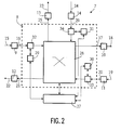
- a network interface 7 with four ring connections is shown in more detail in FIG. 2.
- the network interface 7 contains a coupling device 8, which is coupled to ring and bridge connections via buffer memories 9 to 14 and forwards the cell current.
- the buffer memory 9 is coupled on the one hand to a receiving ring connection 15 of a first ring and on the other hand to a connection 16 which leads to the coupling device 8.
- the buffer memory 9 also receives a first receive clock signal, which is derived from the cell current of the receive ring connection 15, and an internal clock signal from a clock generator of the network interface 7.
- the buffer memory 10 is coupled to the coupling device 8 via a connection 17 and supplies a cell current a transmit ring connector 18 of the first ring.
- the buffer clock 10 is supplied with the internal clock signal and a first transmit clock signal which is derived, for example, from the internal clock signal.
- the buffer memory 11 receives a cell current from a reception ring connection 19 of a second ring and supplies a cell current via a connection 20 to the coupling device 8. From a connection 21 of the coupling device 8, the buffer memory 12 receives cells which are connected to a transmission ring connection 22 of the second ring be forwarded.
- the buffer memory 11 receives a second receive clock signal, which is derived from the cell current of the receive ring connector 19 is derived, and the internal clock signal.
- the buffer clock 12 is supplied with the internal clock signal and a second transmit clock signal which is derived, for example, from the internal clock signal.
- a bridge connection 23 is coupled via the buffer memory 13 and a bridge connection 24 is coupled to the network interface 7 via the buffer memory 14.
- the buffer memory 13, which receives a cell current from the coupling device 8, is coupled to the coupling device 8 via a connection 25.
- the buffer clock 13 is also supplied with the internal clock signal and, if appropriate, a first station signal from a station connected to the bridge connections 23 and 24.
- the buffer memory 14, which is supplied with a cell stream from a network interface of another ring system or a station, is coupled to a station or a network interface of another ring system via the bridge connection 24 and to the coupling device 8 via a connection 26.
- This buffer memory 14 may receive a second station signal and the internal clock signal.
- the cell current is adapted to a clock signal.
- the derivation of the various clock signals from the cell current and the generation of the internal clock signal in the clock generator are not shown in more detail here.
- the station clock signals can, for example, be the same as the internal clock signal. In this case, no buffer memories 13 and 14 are required.
- the network interface 7 also contains a control arrangement 27 which controls the coupling device 8 and is used, for example, for establishing and clearing the connection.
- the control arrangement 27, which can be implemented as a microprocessor, can also receive and generate cells.
- the coupling device 8 also contains a switching matrix 28, three path storage arrangements 29, 30 and 31 and three receiving circuits 32, 33 and 34.
- the receiving circuits 32, 33 and 34 each evaluate the head fields of cells arriving via connections 16, 20 and 26.
- Address information contained in the header field is used to control various tables for the path memory arrangements 29, 30 and 31 connected to the receiving circuits 32, 33 and 34.
- the data stored in the tables are used by the receiving circuits 32, 33 and 34, respectively, to organize the further processing and forwarding of the cell.
- the receiving circuit 32 can copy the cell and provide it with new address information.
- the original cell is e.g. given via the switching matrix 28 to the bridge connection 23 and the copied cell via the switching matrix 28 to the buffer memory 10. There is still the possibility that the switching matrix 28 performs this copying function.
- the receiving circuit 32 is coupled to the buffer memory 9 via the connection 16 and forwards received cells to the switching matrix 28.
- the path memory arrangement 29 is connected to the receiving circuit 32.
- the receiving circuit 33 is connected to the path memory arrangement 30, receives cells from the buffer memory 11 and passes cells on to the switching matrix 28.
- the receiving circuit 34 which is connected to the path memory arrangement 31, is arranged between the switching matrix 28 and the connection 26.
- Two types of useful cells are transmitted via the ring connections 15 and 18 of the first ring and via the ring connections 19 and 22.
- user cells which in their information field, for. B. messages or data of the user of a previously established connection and on the other hand control cells that contain control information in their information field.
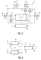
- the network interface 47 operates in a similar manner to the network interface 7 2.
- cells are transmitted between the ring connections 48 and 49, bridge connections 50 and 51 and a control arrangement 52 by a coupling device 53.
- the coupling device 53 contains a switching matrix 54, two receiving circuits 55 and 56 and two path storage arrangements 57 and 58.
- the ring connection 48 is coupled via a buffer memory 59 to the receiving circuit 55 via a connection 60.
- the receiving circuit 55 which is coupled to the path storage arrangement 57, forwards received cells to the switching matrix 54.
- the path memory arrangement 57 may provide the receiving circuit 55 with new control information for the header field of the received cell.
- the switching matrix 54 is further coupled to the ring connection 49 via a connection 65 and a buffer memory 66.
- the bridge connections 50 and 51 are also connected to buffer memories 61 and 62, respectively.
- the buffer memory 61 is supplied with cells from the switching matrix 54 via a connection 63.
- the reception circuit 56 is arranged between the buffer memory 62 and the switching matrix 54 and is coupled to the path memory arrangement 58.
- the receiving circuit 56 and the buffer memory 62 are coupled to one another via a connection 64.
- the control arrangement 52 is used to control the path storage arrangements 57 and 58 and receives at least cells from the switching matrix 54.
- a network interface with four ring connections can also be formed from three network connections, each with two ring connections, as shown in FIG. 3.
- 4 shows three network interfaces 67, 68 and 69.
- the ring connections 70 and 71 of the network interface 68 and the ring connections 73 and 74 of the network interface 69 also form ring connections in this interconnection.
- the bridge connection 75 of the network interface 68 is the ring connection of the network interface 67, the bridge connections 77 and 78 of which are also the bridge connections in this interconnection.
- the further ring connection of the network interface 67 is with the bridge connection 76 Network interface 69 connected.
- the bridge connection 72 still connects the two network interfaces 68 and 69.
- a network interface therefore routes cells from one ring connection to the other ring connection of the same ring, to a bridge or station connection or, in the case of four ring connections, to the ring connection of the other ring.
- a cell on a bridge or station connection is passed on to a ring connection. Cells can also be received and sent by the control arrangement of the network interface.
- VCI virtual channel identifier
- VPI virtual path identifier
- the VCI and the VPI are provided for different information than in the standardization proposals.
- the VPI contains information about the address (address information) or the destination (network node) of a cell in a ring system.
- the VCI is used to specify the user-specific identifier for a connection, the type of connection and the cell type.
- the VCI is also used as an address for a ring system.
- a control arrangement 27 of the network interface 7 or a control arrangement 52 of the network interface 47 controls the connection establishment of an assigned station with other stations.
- the corresponding control processes for the Establishing and clearing down connections can be found, for example, in European patent application EP-0 641 105 A2.
- the path storage arrangements 29 to 31 of the network interface 7 or the path storage arrangements 57 and 58 of the network interface 47 contain information which is evaluated by the associated receiving circuits 32 to 34 or 55 and 56 in order to organize the further processing and forwarding of the received cell. For example, a cell can be assigned a different address, copied or deleted.
- the path storage arrangements 29 to 31 or 57 and 58 can be changed by the respective control arrangement 27 or 52, for example in the event of an error or on the basis of certain information from the network management system.
- a cell generated by the network node f of the ring system B receives the address (C, f) and is transmitted via the network nodes e and d to the network node c of the ring system B and via the associated bridge connections to the network node f of the ring system C.
- the address (C, f) is replaced by a new address (D, a).
- the cell then reaches network node a of ring system D via network nodes e and d of ring system C.
- a new address (E, a) has been inserted, the cell runs via network node d of ring system D to network node a of ring system E.
- F, a a new address in the header of the cell used and given the cell via node d (ring system E) to node a of ring system F.
- the cell reaches network node d via network nodes b and c of ring system F.
- a ring connection or a bridge or station connection can be interrupted or a network node can fail.
- a network interface that detects such an error reports this error to the network management system.
- Such a fault is e.g. after sending out control cells that are not received again or detected by a loss of synchronization.
- the network management system makes this error information available, so that path storage arrangements in the network interfaces can be changed accordingly by the associated control arrangement.
- the network interface If an error occurs on a ring connection between two network interfaces, the network interface receiving no further cells due to the error informs the network management system. The network interface sending out the cells switches a loop after receiving the error information from the network management system. This means that all cells to be routed via the defective ring connection are looped onto the ring connection of the other ring. However, this is only possible if there is a network interface with four ring connections. Otherwise, in the case of a network interface with two ring connections, the cells are deleted.
- a network node detecting the error informs the network management system. Be further In the network interfaces connected via the bridge connection, the entries in the routing memory arrangements are changed. A cell that is to be passed through the bridge connections is then only forwarded by the corresponding coupling devices via the ring and not to a bridge connection.
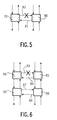
- 5 shows an example with two network interfaces 79 and 80.
- a bridge connection 81 supplies cells from the network interface 80 to a first ring system of the network interface 79 to a second ring system. Cells are normally passed from the network interface 79 to the network interface 80 via the bridge connection 82.
- This bridge connection 82 is interrupted, for example. The cells are then no longer passed through the bridge connections 81 and 82, but remain in the respective ring system, where they may be destroyed if there is no further connection between the two ring systems.
- FIG. 6 shows an example in which there is a further bridge connection between two ring systems.
- a bridge connection 83 or 84 between a network interface 85 of a first ring system and a network interface 86 of a second ring system is interrupted. Cells which are to get from one ring system to the other via the bridge connections 83 and 84 are therefore transmitted via further bridge connections 87 or 88 between the network interface 89 of the first ring system and the network interface 90 of the second ring system.
- the path storage arrangements in the network interfaces 85, 86, 89 and 90 are thus set up so that both cells can be transferred from one ring system to the other.
- the path storage arrangements of the network interfaces 85 and 89 and the network interfaces 86 and 90 have the same content. This ensures that if a bridge connection fails, cells can be transferred between ring systems via further bridge connections. 6, the network interfaces 85, 86, 89 and 90 each have four ring connections. It is also possible to use network interfaces with two ring connections each.
Abstract
Description
Die Erfindung bezieht sich auf ein lokales, nach dem asynchronen Transfermodus (ATM) arbeitendes Netzwerk zur Übertragung von Zellen mit mehreren Netzwerkschnittstellen.The invention relates to a local network operating according to the asynchronous transfer mode (ATM) for the transmission of cells with several network interfaces.
Ein lokales Netzwerk (LAN), welches nach dem asynchronen Transfermodus arbeitet, ist aus der EP 0 641 105 A2 bekannt. Dieses Netzwerk enthält mehrere Stationen und zugeordnete Netzwerkschnittstellen, die jeweils einen Sende- und Empfangs-Ringanschluß aufweisen. Über den so gebildeten Ring werden Zellen übertragen, die Adreßinformationen über den Bestimmungsort beispielsweise einer bestimmten Station enthalten. Eine Netzwerkschnittstelle enthält eine Koppelvorrichtung und eine Steueranordnung. Die Koppelvorrichtung enthält eine Wegespeicheranordnung, die dem Empfangs-Ringanschluß zugeordnet ist, und eine Wegespeicheranordnung, welche einem Empfangs-Stationsanschluß zugeordnet ist. Anhand der Wegespeicheranordnungen werden bei Empfang einer Zelle die entsprechenden Schalt- oder Kopplungsvorgänge in der Koppelvorrichtung durchgeführt. Beispielsweise wird eine eintreffende Zelle anhand der Adreßinformationen zu der Steueranordnung, zur Station und/oder zum Ring weitergeleitet.A local area network (LAN) which operates according to the asynchronous transfer mode is known from EP 0 641 105 A2. This network contains several stations and assigned network interfaces, each of which has a send and receive ring connection. Cells that contain address information about the destination, for example of a particular station, are transmitted via the ring formed in this way. A network interface contains a coupling device and a control arrangement. The coupling device contains a path storage arrangement which is assigned to the receiving ring connection and a path storage arrangement which is assigned to a receiving station connection. On the basis of the path storage arrangements, the corresponding switching or coupling operations are carried out in the coupling device when a cell is received. For example, an incoming cell is forwarded to the control arrangement, the station and / or the ring on the basis of the address information.
Bei Verwendung eines asynchronen Transfermodus in einem System werden Nutzinformationen, z.B. Fernsprech-, Bild- oder Tonsignale, in Blöcken fester Länge über Anordnungen zur digitalen Signalverarbeitung gesendet. Als ein Block fester Länge wird eine Zelle bezeichnet, die eine vorbestimmte Anzahl von Bytes (z.B. 53 Bytes) aufweist. Jede Zelle besteht aus einem Kopffeld mit einer Länge von beispielsweise 5 Byte und einem Informationsfeld, in dem die Nutzinformation untergebracht ist, mit einer Länge von beispielsweise 48 Byte. In einem solchen Kopffeld sind Adreßinformationen, Daten zur Fehlererkennung und Daten für Steuerinformationen vorhanden. Unter Adreßinformationen fallen Bündelkennungen und Verbindungskennungen. Die Verbindungskennung, die auch als VCI (Virtual Channel Identifier) bezeichnet wird, enthält die Angabe über den Bestimmungsort der Zelle in dem System. Zur Übermittlung einer Zelle wird anhand der Verbindungskennung ein virtueller Kanal zur Verfügung gestellt. In der Regel wird ein VCI nach Erreichen einer Vermittlungsstelle jeweils verändert. Ein Bündel mehrerer virtueller Kanäle wird als virtueller Pfad bezeichnet. Ein virtueller Pfad wird durch die Bündelkennung gekennzeichnet. Ein solcher virtueller Pfad wird VPI (Virtual Path Identifier) genannt. Zellen sind aufeinanderfolgend bestimmten Zeitabschnitten zugeordnet. Die Dauer eines solchen Zeitabschnittes hängt von der zugrundegelegten Taktfrequenz der Übermittlungskomponente ab. Falls keine Nutzinformation vorhanden ist, werden in einem solchen Zeitabschnitt Leerzellen übertragen, d.h. Zellen ohne Nutzinformation. Zellen, die eine Nutzinformation beinhalten, werden als Nutzzellen bezeichnet.When using an asynchronous transfer mode in a system, useful information, for example telephone, picture or sound signals, is sent in blocks of fixed length via arrangements for digital signal processing. A fixed length block is a cell that has a predetermined number of bytes (eg 53 bytes). Each cell consists of a header field with a length of, for example, 5 bytes and an information field in which the useful information is housed, with a length of 48 bytes, for example. Address information, data for error detection and data for control information are present in such a header field. Address information includes bundle identifiers and connection identifiers. The connection identifier, which is also referred to as VCI (Virtual Channel Identifier), contains the information about the destination of the cell in the system. To transmit a cell, a virtual channel is made available based on the connection identifier. As a rule, a VCI is changed after reaching an exchange. A bundle of several virtual channels is called a virtual path. A virtual path is identified by the bundle identifier. Such a virtual path is called VPI (Virtual Path Identifier). Cells are sequentially assigned to certain time periods. The duration of such a time period depends on the underlying clock frequency of the transmission component. If no useful information is available, empty cells are transmitted in such a time period, ie cells without useful information. Cells that contain useful information are referred to as useful cells.
Das aus der EP 0 641 105 A2 bekannte lokale Netzwerk besteht nur aus einem Ringsystem und gibt keine Möglichkeiten zum Austausch von Zellen über mehrere Ringsysteme an. Ein Ringsystem kann dabei einen Ring oder zwei Ringe für gegenläufige Zellenströme aufweisen. Ein Ring stellt einen geschlossenen Signalweg über mehrere Netzwerkschnittstellen dar.The local network known from EP 0 641 105 A2 consists of only one ring system and does not specify any possibilities for exchanging cells over several ring systems. A ring system can have one ring or two rings for countercurrent cell currents. A ring represents a closed signal path across several network interfaces.
Aus der DE 40 02 022 A1 ist ein Verfahren und eine Anordnung zur hochverfügbaren Übertragung von Daten zwischen zwei nach dem Token-Passing-Prinzip arbeitenden Busssystem bekannt. Die beiden Busssysteme sind über zwei zum Austausch von Daten vorgesehenen Koppelstrecken miteinander verbunden. Eine Koppelstrecke ist aktiv und die andere Koppelstrecke befindet sich im Stand-by-Betrieb. Die im Stand-by-Betrieb befindliche Koppelstrecke überprüft die ordnungsgemäße Token-Weitergabe der aktiven Koppelstrecke. Mit dem Ausfall der aktiven Koppelstrecke wird die bisher im Stand-by-Betrieb arbeitende Koppelstrecke aktiv geschaltet. Somit ist bei dieser Anordnung immer nur eine Koppelstrecke aktiv.DE 40 02 022 A1 discloses a method and an arrangement for the highly available transmission of data between two bus systems operating according to the token passing principle. The two bus systems are connected to one another via two coupling links provided for the exchange of data. One coupling link is active and the other coupling link is in stand-by mode. The coupling link in stand-by mode checks the correct token transfer of the active coupling link. With the failure of the active coupling link, the coupling link previously operating in stand-by mode is activated. Thus, only one coupling link is active in this arrangement.
Der Erfindung liegt daher die Aufgabe zugrunde, ein lokales, nach dem asynchronen Transfermodus arbeitendes Netzwerk zu schaffen, bei welchen auch ein Austausch von Zellen zwischen Ringsystemen möglich ist.The object of the invention is therefore to create a local network which operates according to the asynchronous transfer mode and in which an exchange of cells between ring systems is also possible.
Die Erfindung wird durch ein lokales, nach dem asynchronen Transfermodus arbeitendes Netzwerk der eingangs genannten Art dadurch gelöst, daß wenigstens zwei Ringsysteme mit jeweils zwei Netzwerkschnittstellen vorgesehen sind, die jeweils wenigstens einen Brückenanschluß aufweisen und daß eine erste Netzwerkschnittstelle eines ersten Ringsystems und eine erste Netzwerkschnittstelle eines zweiten Ringsystems über wenigstens einen ersten Brückenanschluß zur Übertragung des Zellenstroms zwischen den beiden Ringsystemen und eine zweite Netzwerkschnittstelle des ersten Ringsystems und eine zweite Netzwerkschnittstelle des zweiten Ringsystems über wenigstens einen zweiten Brückenanschluß zur Leitung des Zellenstroms zwischen den beiden Ringsystemen gekoppelt sind.The invention is achieved by a local network operating according to the asynchronous transfer mode of the type mentioned in the introduction in that at least two ring systems are provided, each with two network interfaces, each having at least one bridge connection, and in that a first network interface of a first ring system and a first network interface of a second ring system via at least a first bridge connection for transmitting the cell current between the two ring systems and a second network interface of the first ring system and a second network interface of the second ring system are coupled via at least a second bridge connection for conducting the cell current between the two ring systems.
Das erfindungsgemäße lokale Netzwerk enthält wenigstens zwei Ringsysteme mit einem oder zwei Ringen. Zellen können über jeweils erste Netzwerkschnittstellen von einem Ringsystem ins andere Ringsystem übertragen werden. Die beiden ersten Netzwerkschnittstellen sind dabei über wenigstens einen Brückenanschluß miteinander gekoppelt. Das erste und zweite Ringsystem enthalten jeweils auch zweite Netzwerkschnittstellen, die über wenigstens einen zweiten Brückenanschluß miteinander gekoppelt sind. Der Zellstrom kann somit entweder über die ersten oder zweiten Netzwerkschnittstellen fließen. Bei Ausfall eines Brückenanschlusses kann durch die erfindungsgemäßen Maßnahmen der Zellstrom über die jeweiligen anderen Brückenanschlüsse fließen.The local network according to the invention contains at least two ring systems with one or two rings. Cells can be transferred from one ring system to the other ring system via first network interfaces. The first two network interfaces are coupled to one another via at least one bridge connection. The first and second ring systems each also contain second network interfaces which are coupled to one another via at least one second bridge connection. The cell stream can thus flow either through the first or second network interfaces. If a bridge connection fails, the measures according to the invention allow the cell current to flow through the respective other bridge connections.
Bei einer Unterbrechung der ersten Brückenanschlüsse sind die ersten Netzwerkschnittstellen nicht zur Weiterleitung von Zellen, deren Bestimmungsort das jeweils andere Ringsystem ist, in das andere Ringsystem vorgesehen. Ebenso sind bei einer Unterbrechung der zweiten Brückenanschlüsse die zweiten Netzwerkschnittstellen nicht zur Weiterleitung von Zellen, deren Bestimmungsort das jeweils andere Ringsystem ist, in das andere Ringsystem vorgesehen. Die Netzwerkschnittstelle welche einem unterbrochenen Brückenanschluß zugeordnet ist, läßt also keine Zelle mehr zum Brückenanschluß fließen, sondern leitet eine Zelle auf dem Ring weiter.If the first bridge connections are interrupted, the first network interfaces are not intended for forwarding cells whose destination is the respective other ring system into the other ring system. Likewise, if the second bridge connections are interrupted, the second network interfaces are not provided for forwarding cells whose destination is the respective other ring system into the other ring system. The network interface, which is assigned to an interrupted bridge connection, therefore no longer flows a cell to the bridge connection, but forwards a cell on the ring.
In einer Weiterbildung der Erfindung ist vorgesehen, daß eine erste oder zweite Netzwerkschnittstelle eine Koppelvorrichtung zur Kopplung von wenigstens einem Empfangs- und einem Sende-Ringanschluß und zwei Brückenanschlüssen enthält, daß einem Empfangs-Ringanschluß und einem Brückenanschluß jeweils eine Wegespeicheranordnung zur Steuerung der Wege in der Koppelvorrichtung nach Entnahme von Adreßinformationen aus dem Kopffeld einer Zelle zugeordnet sind und daß die Wegespeicheranordnungen der ersten und zweiten Netzwerkschnittstellen eines Ringsystems gleiche Inhalte aufweisen. Da die Wegespeicheranordnungen in den Netzwerkschnittstellen eines Ringsystems die gleichen Inhalte aufweisen, kann bei Ausfall eines Brückenanschlusses ohne Verzögerung der Zellstrom über die jeweils anderen Brückenanschlüsse geleitet werden.In a development of the invention it is provided that a first or second network interface contains a coupling device for coupling at least one receive and one transmit ring connection and two bridge connections, that one receive ring connection and one bridge connection each have a path storage arrangement for controlling the paths in the Coupling device are assigned to a cell after taking address information from the header field and that the path storage arrangements of the first and second network interfaces of a ring system have the same content. Since the path storage arrangements in the network interfaces of a ring system have the same contents, if one bridge connection fails, the cell current can be passed over the other bridge connections without delay.
Die Erfindung bezieht sich auch auf ein Verfahren zur Übertragung von Zellen in einem lokalen, nach dem asynchronen Transfermodus (ATM) arbeitenden, mehrere Netzwerkschnittstellen enthaltenden Netzwerk. Hierbei werden Zellen zwischen einer ersten Netzwerkschnittstelle eines ersten Ringsystems und einer ersten Netzwerkschnittstelle eines zweiten Ringsystems über wenigstens einen ersten Brückenanschluß und zwischen einer zweiten Netzwerkschnittstelle des ersten Ringsystems und einer zweiten Netzwerkschnittstelle des zweiten Ringsystems über wenigstens einen zweiten Brückenanschluß übertragen.The invention also relates to a method for the transmission of cells in a local network which operates according to the asynchronous transfer mode (ATM) and contains several network interfaces. Here, cells are transmitted between a first network interface of a first ring system and a first network interface of a second ring system via at least a first bridge connection and between a second network interface of the first ring system and a second network interface of the second ring system via at least a second bridge connection.
Ausführungsbeispiele der Erfindung werden nachstehend anhand der Figuren näher erläutert. Es zeigen:
- Fig. 1
- ein lokales Netzwerk,
- Fig. 2
- eine in dem lokalen Netzwerk nach Fig. 1 verwendbare Netzwerkschnittstelle mit vier Ringanschlüssen,
- Fig. 3
- eine in dem lokalen Netzwerk nach Fig. 1 verwendbare Netzwerkschnittstelle mit zwei Ringanschlüssen,
- Fig. 4
- eine aus drei Netzwerkschnittstellen mit jeweils zwei Ringanschlüssen gebildete Netzwerkschnittstelle mit vier Ringanschlüssen,
- Fig. 5
- zwei über Brückenanschlüsse gekoppelte Netzwerkschnittstellen von zwei Ringsystemen und
- Fig. 6
- vier über Brückenanschlüsse gekoppelte Netzwerkschnittstellen von zwei Ringsystemen.
- Fig. 1
- a local network,
- Fig. 2
- FIG. 1 a network interface with four ring connections that can be used in the local network according to FIG. 1,
- Fig. 3
- 1 which can be used in the local network according to FIG. 1 with two ring connections,
- Fig. 4
- a network interface formed from three network interfaces, each with two ring connections, with four ring connections,
- Fig. 5
- two network interfaces of two ring systems and
- Fig. 6
- four network interfaces of two ring systems coupled via bridge connections.
In Fig. 1 ist ein Ausführungsbeispiel eines lokalen Netzwerks mit sechs Ringsystemen 1 bis 6 dargestellt. Ein Ringsystem 1 bis 6 kann entweder aus einem oder zwei Ringen bestehen. Die Ringsysteme 1 und 2 enthalten einen und die Ringsysteme 3 bis 6 zwei Ringe. Ein Ring stellt einen geschlossenen Signalweg über mehrere Netzknoten dar. Die Ringsysteme 3 bis 6 bilden jeweils zwei gegenläufige Ringe, d.h. die Signale laufen auf den Ringen jeweils in entgegengesetzter Richtung. Ein Netzknoten, der in den Ringsystemen 1 bis 6 jeweils als Rechteck dargestellt ist, umfaßt eine Netzwerkschnittstelle mit zwei oder vier Ringanschlüssen und zwei Brückenanschlüssen.1 shows an embodiment of a local network with six
An die Brückenanschlüsse ist entweder eine Station oder eine Netzwerkschnittstelle eines anderen Ringsystems angeschlossen. Beispielsweise sind in der Fig. 1 für das Ringsystem 4 insgesamt drei Netzwerkschnittstellen mit Stationen und vier Netzwerkschnittstellen mit Netzwerkschnittstellen der Ringsysteme 3 und 5 verbunden. Eine Station kann beispielsweise ein Bildfernsprecher, ein Personal-Computer oder eine Workstation bzw. ein Fernsprecher sein. Die Nachrichten bzw. Informationen, die von den Stationen bzw. den Netzwerkschnittstellen stammen, werden nach dem asynchronen Transfermodus mittels Zellen übertragen. Eine Zelle enthält ein Kopffeld mit beispielsweise 5 Byte und ein Informationsfeld mit beispielsweise 48 Byte. Die im Kopffeld der Zelle enthaltenen Informationen dienen insbesondere zur Adressierung und zur Durchführung von Vermittlungsfunktionen. Jeder Netzknoten ist noch mit einem nicht dargestellten Netzwerkmanagementsystem zur Steuerung des lokalen Netzwerkes gekoppelt.Either a station or a network interface of another ring system is connected to the bridge connections. For example, a total of three network interfaces with stations and four network interfaces with network interfaces of the ring systems 3 and 5 are connected to the
Eine Netzwerkschnittstelle 7 mit vier Ringanschlüssen ist in der Fig. 2 detaillierter dargestellt. Die Netzwerkschnittstelle 7 enthält eine Koppelvorrichtung 8, die über Pufferspeicher 9 bis 14 mit Ring und Brückenanschlüssen gekoppelt ist und den Zellenstrom weitervermittelt.A
Der Pufferspeicher 9 ist einerseits mit einem Empfangs-Ringanschluß 15 eines ersten Ringes und andererseits mit einem Anschluß 16, der zur Koppelvorrichtung 8 führt, gekoppelt. Der Pufferspeicher 9 erhält noch ein erstes Empfangstaktsignal, welches aus dem Zellenstrom des Empfangs-Ringanschlusses 15 abgeleitet ist, und ein internes Taktsignal von einem Taktgenerator der Netzwerkschnittstelle 7. Der Pufferspeicher 10 ist über einen Anschluß 17 mit der Koppelvorrichtung 8 gekoppelt und liefert einen Zellenstrom an einen Sende-Ringanschluß 18 des ersten Ringes. Dem Pufferspeicher 10 wird das interne Taktsignal und ein erstes Sende-Taktsignal geliefert, welches beispielsweise aus dem internen Taktsignal abgeleitet ist.The buffer memory 9 is coupled on the one hand to a receiving
Die Pufferspeicher 11 erhält einen Zellenstrom von einem Empfangs-Ringanschluß 19 eines zweiten Ringes und liefert einen Zellenstrom über einen Anschluß 20 zur Koppelvorrichtung 8. Von einem Anschluß 21 der Koppelvorrichtung 8 empfängt der Pufferspeicher 12 Zellen, die an einen Sende-Ringanschluß 22 des zweiten Ringes weiterleitet werden. Der Pufferspeicher 11 erhält ein zweites Empfangstaktsignal, welches aus dem Zellenstrom des Empfangs-Ringanschlusses 19 abgeleitet ist, und das interne Taktsignal. Dem Pufferspeicher 12 wird das interne Taktsignal und ein zweites Sende-Taktsignal geliefen, welches beispielsweise aus dem internen Taktsignal abgeleitet ist.The
Ein Brückenanschluß 23 ist über den Pufferspeicher 13 und ein Brückenanschluß 24 ist über den Pufferspeicher 14 mit der Netzwerkschnittstelle 7 gekoppelt. Der Pufferspeicher 13, der einen Zellenstrom von der Koppelvorrichtung 8 erhält, ist über einen Anschluß 25 mit der Koppelvorrichtung 8 gekoppelt. Dem Pufferspeicher 13 wird ebenfalls das interne Taktsignal und gegebenenfalls ein von einer an die Brückenanschlüsse 23 und 24 angeschlossenen Station ein erstes Stationssignal geliefert. Der Pufferspeicher 14, dem ein Zellenstrom von einer Netzwerkschnittstelle eines anderen Ringsystems oder einer Station geliefert wird, ist über den Brückenanschluß 24 mit einer Station oder einer Netzwerkschnittstelle eines anderen Ringsystems und über einen Anschluß 26 mit der Koppelvorrichtung 8 gekoppelt. Dieser Pufferspeicher 14 erhält gegebenenfalls ein zweites Stationssignal und das interne Taktsignal. In den Pufferspeichern 9 bis 14 findet jeweils eine Anpassung des Zellenstroms an ein Taktsignal statt. Die Ableitung der verschiedenen Taktsignale aus dem Zellenstrom und die Erzeugung des internen Taktsignals im Taktgenerator sind hier nicht näher dargestellt. Die Stationstaktsignale können beispielsweise gleich dem internen Taktsignal sein. In diesem Fall werden keine Pufferspeicher 13 und 14 benötigt.A
In der Netzwerkschnittstelle 7 ist noch eine die Koppelvorrichtung 8 steuernde Steueranordnung 27 enthalten, die beispielsweise zum Verbindungssaufbau und -abbau dient. Die Steueranordnung 27, die als Mikroprozessor realisiert sein kann, kann auch Zellen erhalten und erzeugen.The
In der Koppelvorrichtung 8 ist noch ein Koppelfeld 28, drei Wegespeicheranordnungen 29, 30 und 31 und drei Empfangsschaltungen 32, 33 und 34 enthalten. In den Empfangsschaltungen 32, 33 und 34 werden jeweils die Kopffelder von über Anschlüssen 16, 20 und 26 ankommenden Zellen ausgewertet.The
Im Kopffeld enthaltene Adresseninformationen werden zur Ansteuerung verschiedener Tabellen für die mit den Empfangsschaltungen 32, 33 und 34 verbundenen Wegespeicheranordnungen 29, 30 und 31 verwendet. Die in den Tabellen abgelegten Daten werden jeweils von den Empfangsschaltungen 32, 33 und 34 verwendet, um die weitere Verarbeitung und Weiterleitung der Zelle zu organisieren. Beispielsweise kann die Empfangsschaltung 32 die Zelle kopieren und mit neuen Adresseninformationen versehen. Die Originalzelle wird z.B. über das Koppelfeld 28 an den Brückenanschluß 23 und die kopierte Zelle über das Koppelfeld 28 an den Pufferspeicher 10 gegeben. Es besteht noch die Möglichkeit, daß das Koppelfeld 28 diese Kopierfunktion durchführt.Address information contained in the header field is used to control various tables for the
Die Empfangsschaltung 32 ist über den Anschluß 16 mit dem Pufferspeicher 9 gekoppelt und leitet empfangene Zellen zum Koppelfeld 28 weiter. Die Wegespeicheranordnung 29 ist mit der Empfangschaltung 32 verbunden. Die Empfangsschaltung 33 ist mit der Wegespeicheranordnung 30 verbunden, erhält Zellen von dem Pufferspeicher 11 und gibt Zellen an das Koppelfeld 28 weiter. Zwischen dem Koppelfeld 28 und dem Anschluß 26 ist die Empfangsschaltung 34 angeordnet, die mit der Wegespeicheranordnung 31 verbunden ist.The receiving
Über die Ringanschlüsse 15 und 18 des ersten Ringes und über die Ringanschlüsse 19 und 22 werden zwei Arten von Nutzzellen übertragen. Einerseits Anwenderzellen, die in ihrem Informationsfeld z. B. Nachrichten oder Daten des Benutzers einer zuvor aufgebauten Verbindung enthalten und andererseits Kontrollzellen, die in ihrem Informationsfeld Steuerungsinformationen enthalten.Two types of useful cells are transmitted via the
Fig. 3 zeigt eine Netzwerkschnittstelle 47 mit zwei Ringanschlüssen 48 und 49. Die Netzwerkschnittstelle 47 arbeitet auf ähnliche Weise wie die Netzwerkschnittstelle 7 der Fig. 2. Zellen werden bei dieser Netzwerkschnittstelle zwischen den Ringanschlüssen 48 und 49, Brückenanschlüssen 50 und 51 und einer Steueranordnung 52 von einer Koppelvorrichtung 53 übertragen. Die Koppelvorrichtung 53 enthält ein Koppelfeld 54, zwei Empfangsschaltungen 55 und 56 und zwei Wegespeicheranordnungen 57 und 58. Der Ringanschluß 48 ist über einen Pufferspeicher 59 einen Anschluß 60 mit der Empfangsschaltung 55 gekoppelt. Die Empfangsschaltung 55, die mit der Wegespeicheranordnung 57 gekoppelt ist, leitet empfangene Zellen an das Koppelfeld 54 weiter. Die Wegespeicheranordnung 57 liefert der Empfangsschaltung 55 gegebenenfalls neue Steuerungsinformationen für das Kopffeld der empfangenen Zelle. Das Koppelfeld 54 ist ferner über einen Anschluß 65 und einem Pufferspeicher 66 mit dem Ringanschluß 49 gekoppelt.3 shows a
Die Brückenanschlüsse 50 und 51 sind ebenfalls jeweils mit Pufferspeichern 61 und 62 verbunden. Dem Pufferspeicher 61 werden über einen Anschluß 63 Zellen vom Koppelfeld 54 geliefert. Zwischen dem Pufferspeicher 62 und dem Koppelfeld 54 ist die Empfangsschaltung 56 angeordnet, die mit der Wegespeicheranordnung 58 gekoppelt ist. Die Empfangsschaltung 56 und der Pufferspeicher 62 sind über einen Anschluß 64 miteinander gekoppelt. Die Steueranordnung 52 dient zur Steuerung der Wegespeicheranordnungen 57 und 58 und erhält zumindestens Zellen von dem Koppelfeld 54.The
Eine Netzwerkschnittstelle mit vier Ringanschlüssen, wie in Fig. 2 gezeigt, läßt sich auch aus drei Netzwerkanschlüssen mit jeweils zwei Ringanschlüssen, wie in Fig. 3 gezeigt, bilden. In Fig. 4 sind drei Netzwerkschnittstellen 67, 68 und 69 dargestellt. Die Ringanschlüsse 70 und 71 der Netzwerkschnittstelle 68 und die Ringanschlüsse 73 und 74 der Netzwerkschnittstelle 69 bilden auch bei dieser Zusammenschaltung Ringanschlüsse. Der Brückenanschluß 75 der Netzwerkschnittstelle 68 ist der Ringanschluß der Netzwerkschnittstelle 67, deren Brückenanschlüsse 77 und 78 auch die Brückenanschlüsse bei dieser Zusammenschaltung sind. Der weitere Ringanschluß der Netzwerkschnittstelle 67 ist mit dem Brückenanschluß 76 der Netzwerkschnittstelle 69 verbunden. Der Brückenanschluß 72 verbindet noch die beiden Netzwerkschnittstellen 68 und 69.A network interface with four ring connections, as shown in FIG. 2, can also be formed from three network connections, each with two ring connections, as shown in FIG. 3. 4 shows three
Eine Netzwerkschnittstelle leitet also Zellen von einem Ringanschluß zu dem anderen Ringanschluß des gleichen Rings, zu einem Brücken- oder Stationsanschluß oder auch bei vier Ringanschlüssen zu dem Ringanschluß des anderen Rings. Eine Zelle auf einem Brücken- oder Stationsanschluß wird zu einem Ringanschluß weitergegeben. Zellen können auch von der Steueranordnung der Netzwerkschnittstelle empfangen und gesendet werden.A network interface therefore routes cells from one ring connection to the other ring connection of the same ring, to a bridge or station connection or, in the case of four ring connections, to the ring connection of the other ring. A cell on a bridge or station connection is passed on to a ring connection. Cells can also be received and sent by the control arrangement of the network interface.
Bestimmte Bits im Kopffeld einer Zelle sind für den VCI (virtual channel identifier) reserviert. Diese Angabe enthält nach Normungsvorschlägen den Bestimmungsort einer Zelle und gibt damit eine virtuelle Verbindung an. Des weiteren sind bestimmte Bits im Kopffeld der Zelle für den VPI (virtual path identifier) reserviert, der ein Bündel mehrerer virtueller Verbindungen angibt. Für den VPI sind im Kopffeld der Zelle nach derzeitigen Normungsbestimmungen 8 Bit und für den VCI 16 Bit vorgesehen.Certain bits in the header field of a cell are reserved for the VCI (virtual channel identifier). According to standardization proposals, this specification contains the destination of a cell and thus indicates a virtual connection. Furthermore, certain bits in the header field of the cell are reserved for the VPI (virtual path identifier), which specifies a bundle of several virtual connections. For the VPI, 8 bits are provided in the header field of the cell according to current standards and 16 bits for the VCI.
Der VCI und der VPI werden bei diesem Ausführungsbeispiel für andere Informationen als bei den Normungsvorschlägen vorgesehen. Der VPI enthält Informationen über die Adresse (Adresseninformationen) bzw. den Bestimmungsort (Netzknoten) einer Zelle in einem Ringsystem. Der VCI wird für die Angabe über die anwenderbezogene Kennung für eine Verbindung, die Art der Verbindung und die Zellenart verwendet. Außerdem wird der VCI als Adresse für ein Ringsystem benutzt.In this exemplary embodiment, the VCI and the VPI are provided for different information than in the standardization proposals. The VPI contains information about the address (address information) or the destination (network node) of a cell in a ring system. The VCI is used to specify the user-specific identifier for a connection, the type of connection and the cell type. The VCI is also used as an address for a ring system.
Eine Steueranordnung 27 der Netzwerkschnittstelle 7 oder eine Steueranordnung 52 der Netzwerkschnittstelle 47 steuert den Verbindungsaufbau einer zugeordneten Station mit anderen Stationen. Die entsprechenden Steuerungsvorgänge für den Aufbau und Abbau von Verbindungen kann beispielsweise der europäischen Patentanmeldung EP-0 641 105 A2 entnommen werden.A
Die Wegespeicheranordnungen 29 bis 31 der Netzwerkschnittstelle 7 bzw. die Wegespeicheranordnungen 57 und 58 der Netzwerkschnittstelle 47 enthalten Informationen die von den zugeordneten Empfangsschaltungen 32 bis 34 bzw. 55 und 56 ausgewertet werden, um die weitere Verarbeitung und Weiterleitung der empfangenen Zelle zu organisieren. Beispielsweise kann eine Zelle mit einer anderen Adresse versehen werden, kopiert oder gelöscht werden. Die Wegespeicheranordnungen 29 bis 31 bzw. 57 und 58 können von der jeweiligen Steueranordnung 27 bzw. 52 beispielsweise im Fehlerfall oder aufgrund bestimmter Informationen des Netzwerkmanagementsystems verändert werden.The
Bei einer Verbindung zwischen einem Netzknoten eines ersten Ringsystems und einem Netzknoten eines zweiten Ringsystems müssen bei einem Übertritt einer Zelle von einem Ringsystem in ein anderes Veränderungen des VPI und des VCI durchgeführt werden. Hierzu sind vor dem Verbindungsaufbau entsprechende Einträge in den Wegespeicheranordnungen vorgenommen worden. Es sei angenommen, daß Zellen von dem Ringsystem B des Netzknotens f (B,f) zu dem Ringsystem F des Netzknotens d (F,d) gesendet werden sollen (Fig. 1). Hierbei sei folgender Weg festgelegt: (B,f) - (B,c) - (C,f) - (C,d) - (D,a) - (D,d) - (E,a) - (E,d) - (F,a) - (F,d). Eine von dem Netzknoten f des Ringsystems B erzeugte Zelle erhält die Adresse (C,f) und wird über die Netzknoten e und d zu dem Netzknoten c des Ringsystems B und über die zugehörigen Brückenanschlüsse zum Netzknoten f des Ringsystems C übertragen. Im Netzknoten f des Ringsystems C wird die Adresse (C,f) durch eine neue Adresse (D,a) ersetzt. Anschließend gelangt die Zelle über die Netzknoten e und d des Ringsystems C zum Netzknoten a des Ringsystems D. Nach Einsetzen einer neuen Adresse (E,a) läuft die Zelle über den Netzknoten d des Ringsystems D zu dem Netzknoten a des Ringsystems E. Vor dem Eintritt in das letzte Ringsystem F wird eine neue Adresse (F,a) in das Kopffeld der Zelle eingesetzt und die Zelle über den Knoten d (Ringsystem E) zum Knoten a des Ringsystems F gegeben. Nach einer weiteren Übersetzung gelangt die Zelle über die Netzknoten b und c des Ringsystems F zum Netzknoten d.In the case of a connection between a network node of a first ring system and a network node of a second ring system, changes in the VPI and the VCI must be carried out when a cell transfers from one ring system to another. For this purpose, corresponding entries have been made in the path storage arrangements before the connection is established. It is assumed that cells are to be sent from the ring system B of the network node f (B, f) to the ring system F of the network node d (F, d) (FIG. 1). The following path is defined here: (B, f) - (B, c) - (C, f) - (C, d) - (D, a) - (D, d) - (E, a) - (E , d) - (F, a) - (F, d). A cell generated by the network node f of the ring system B receives the address (C, f) and is transmitted via the network nodes e and d to the network node c of the ring system B and via the associated bridge connections to the network node f of the ring system C. In the network node f of the ring system C, the address (C, f) is replaced by a new address (D, a). The cell then reaches network node a of ring system D via network nodes e and d of ring system C. After a new address (E, a) has been inserted, the cell runs via network node d of ring system D to network node a of ring system E. Before Entry into the last ring system F becomes a new address (F, a) in the header of the cell used and given the cell via node d (ring system E) to node a of ring system F. After a further translation, the cell reaches network node d via network nodes b and c of ring system F.
Wenn ein Fehler im lokalen Netzwerk auftritt, werden von dem einen Fehler detektierenden Netzknoten und dem Netzwerkmanagmentsystem verschiedene Maßnahmen durchgeführt. Beispielsweise kann ein Ringanschluß oder ein Brücken- oder Stationsanschluß unterbrochen werden oder ein Netzknoten ausfallen. Eine Netzwerkschnittstelle, die einen solchen Fehler detektiert, meldet diesen Fehler an das Netzwerkmanagementsystem. Von der Steueranordnung einer Netzwerkschnittstelle wird ein solcher Fehler z.B. nach Aussenden von Kontrollzellen, die nicht wieder empfangen werden oder durch einen Synchronisationsverlust detektiert. Nach Empfang einer Fehlermeldung stellt das Netzwerkmanagementsystem diese Fehlerinformation zur Verfügung, so daß Wegespeicheranordnungen in den Netzwerkschnittstellen von der zugehörigen Steueranordnung entsprechend geändert werden können.If an error occurs in the local network, various measures are carried out by the network node detecting an error and the network management system. For example, a ring connection or a bridge or station connection can be interrupted or a network node can fail. A network interface that detects such an error reports this error to the network management system. Such a fault is e.g. after sending out control cells that are not received again or detected by a loss of synchronization. After receiving an error message, the network management system makes this error information available, so that path storage arrangements in the network interfaces can be changed accordingly by the associated control arrangement.
Tritt ein Fehler auf einem Ringanschluß zwischen zwei Netzwerkschnittstellen auf, so informiert die aufgrund des Fehlers keine weiteren Zellen empfangende Netzwerkschnittstelle das Netzwerkmanagementsystem. Die die Zellen aussendende Netzwerkschnittstelle schaltet nach Empfang der Fehlerinformation von dem Netzwerkmanagementsystem eine Schleife. Das bedeutet, daß alle Zellen, die über den defekten Ringanschluß zu leiten sind, über eine Schleife auf den Ringanschluß des anderen Rings gegeben werden. Dies geht aber nur dann, wenn eine Netzwerkschnittstelle mit vier Ringanschlüssen vorliegt. Im anderen Fall, bei einer Netzwerkschnittstelle mit zwei Ringanschlüssen werden die Zellen gelöscht.If an error occurs on a ring connection between two network interfaces, the network interface receiving no further cells due to the error informs the network management system. The network interface sending out the cells switches a loop after receiving the error information from the network management system. This means that all cells to be routed via the defective ring connection are looped onto the ring connection of the other ring. However, this is only possible if there is a network interface with four ring connections. Otherwise, in the case of a network interface with two ring connections, the cells are deleted.
Liegt ein Fehler auf einem Brückenanschluß vor, d.h. eine oder mehrere Leitungen zwischen zwei Netzknoten zweier Ringsysteme sind defekt, informiert ein den Fehler detektierender Netzknoten das Netzwerkmanagementsystem. Weiter werden in den über den Brückenanschluß verbundenen Netzwerkschnittstellen die Einträge in den Wegespeicheranordnungen verändert. Eine Zelle, die über die Brückenanschlüsse gegeben werden soll, wird dann von den entsprechenden Koppelvorrichtungen nur noch über den Ring und nicht zu einem Brückenanschluß weitergeleitet. In Fig. 5 ist hierzu ein Beispiel mit zwei Netzwerkschnittstellen 79 und 80 dargestellt. Ein Brückenanschluß 81 liefert Zellen von der Netzwerkschnittstelle 80 einem ersten Ringsystem der Netzwerkschnittstelle 79 eines zweiten Ringsystems. Über den Brückenanschluß 82 werden normalerweise Zellen von der Netzwerkschnittstelle 79 zur Netzwerkschnittstelle 80 gegeben. Dieser Brückenanschluß 82 ist beispielsweise unterbrochen. Die Zellen werden dann nicht mehr über die Brückenanschlüsse 81 und 82 gegeben, sondern bleiben im jeweiligen Ringsystem, wo sie gegebenenfalls vernichtet werden, falls keine weitere Verbindung zwischen den beiden Ringsystemen besteht.If there is an error on a bridge connection, ie one or more lines between two network nodes of two ring systems are defective, a network node detecting the error informs the network management system. Be further In the network interfaces connected via the bridge connection, the entries in the routing memory arrangements are changed. A cell that is to be passed through the bridge connections is then only forwarded by the corresponding coupling devices via the ring and not to a bridge connection. 5 shows an example with two
In Fig. 6 ist ein Beispiel dargestellt, bei dem eine weitere Brückenverbindung zwischen zwei Ringsystemen besteht. Es sei ein Brückenanschluß 83 oder 84 zwischen einer Netzwerkschnittstelle 85 eines ersten Ringsystems und einer Netzwerkschnittstelle 86 eines zweiten Ringsystems unterbrochen. Zellen, welche über die Brückenanschlüsse 83 und 84 von einem Ringsystems ins andere gelangen sollen, werden daher über weitere Brückenanschlüsse 87 oder 88 zwischen der Netzwerkschnittstelle 89 des ersten Ringsystems und der Netzwerkschnittstelle 90 des zweiten Ringsystems übertragen. Die Wegespeicheranordnungen in den Netzwerkschnittstellen 85, 86, 89 und 90 sind also so eingerichtet, daß beide Zellen von einem Ringsystem ins andere übertragen werden können. Die Wegespeicheranordnungen der Netzwerkschnittstellen 85 und 89 und der Netzwerkschnittstellen 86 und 90 weisen den gleichen Inhalt auf. Somit ist bei Ausfall eines Brückenanschlusses gewährleistet, daß Zellen über weitere Brückenanschlüsse zwischen Ringsystemen übertragen werden können. In Fig. 6 weisen die Netzwerkschnittstellen 85, 86, 89 und 90 jeweils vier Ringanschlüsse auf. Es ist auch möglich, daß Netzwerkschnittstellen mit jeweils zwei Ringanschlüssen eingesetzt werden.6 shows an example in which there is a further bridge connection between two ring systems. A
Claims (4)
dadurch gekennzeichnet,
characterized by
dadurch gekennzeichnet,
characterized by
dadurch gekennzeichnet,
characterized by
dadurch gekennzeichnet,
characterized by
Applications Claiming Priority (2)
| Application Number | Priority Date | Filing Date | Title |
|---|---|---|---|
| DE19532422 | 1995-09-01 | ||
| DE19532422A DE19532422C1 (en) | 1995-09-01 | 1995-09-01 | Local network operating according to the asynchronous transfer mode (ATM) with at least two ring systems |
Publications (1)
| Publication Number | Publication Date |
|---|---|
| EP0762694A1 true EP0762694A1 (en) | 1997-03-12 |
Family
ID=7771105
Family Applications (1)
| Application Number | Title | Priority Date | Filing Date |
|---|---|---|---|
| EP96202367A Withdrawn EP0762694A1 (en) | 1995-09-01 | 1996-08-26 | Local Asynchronous Transfer Mode (ATM) network with at least two ring systems |
Country Status (4)
| Country | Link |
|---|---|
| US (1) | US6647429B1 (en) |
| EP (1) | EP0762694A1 (en) |
| JP (1) | JPH09116567A (en) |
| DE (1) | DE19532422C1 (en) |
Families Citing this family (27)
| Publication number | Priority date | Publication date | Assignee | Title |
|---|---|---|---|---|
| DE19918896A1 (en) * | 1999-04-26 | 2000-11-02 | Mueschenborn Hans Joachim | Logical network system |
| DE19961399C2 (en) * | 1999-12-20 | 2002-08-22 | Mueschenborn Hans Joachim | Protection of security-critical data in networks |
| DE10004432A1 (en) * | 2000-02-02 | 2001-08-09 | Siemens Ag | Network and network participants, in particular field device, for such a network |
| DE10004426A1 (en) * | 2000-02-02 | 2001-08-09 | Siemens Ag | Network participants, in particular field device, and network with such a network participant |
| US6836839B2 (en) | 2001-03-22 | 2004-12-28 | Quicksilver Technology, Inc. | Adaptive integrated circuitry with heterogeneous and reconfigurable matrices of diverse and adaptive computational units having fixed, application specific computational elements |
| US7962716B2 (en) | 2001-03-22 | 2011-06-14 | Qst Holdings, Inc. | Adaptive integrated circuitry with heterogeneous and reconfigurable matrices of diverse and adaptive computational units having fixed, application specific computational elements |
| US7752419B1 (en) | 2001-03-22 | 2010-07-06 | Qst Holdings, Llc | Method and system for managing hardware resources to implement system functions using an adaptive computing architecture |
| US7653710B2 (en) | 2002-06-25 | 2010-01-26 | Qst Holdings, Llc. | Hardware task manager |
| US7388872B2 (en) * | 2001-04-06 | 2008-06-17 | Montgomery Jr Charles D | Dynamic communication channel allocation method and system |
| US6577678B2 (en) | 2001-05-08 | 2003-06-10 | Quicksilver Technology | Method and system for reconfigurable channel coding |
| US8412915B2 (en) * | 2001-11-30 | 2013-04-02 | Altera Corporation | Apparatus, system and method for configuration of adaptive integrated circuitry having heterogeneous computational elements |
| US6986021B2 (en) | 2001-11-30 | 2006-01-10 | Quick Silver Technology, Inc. | Apparatus, method, system and executable module for configuration and operation of adaptive integrated circuitry having fixed, application specific computational elements |
| US7215701B2 (en) | 2001-12-12 | 2007-05-08 | Sharad Sambhwani | Low I/O bandwidth method and system for implementing detection and identification of scrambling codes |
| US20030108012A1 (en) * | 2001-12-12 | 2003-06-12 | Quicksilver Technology, Inc. | Method and system for detecting and identifying scrambling codes |
| US7403981B2 (en) * | 2002-01-04 | 2008-07-22 | Quicksilver Technology, Inc. | Apparatus and method for adaptive multimedia reception and transmission in communication environments |
| FR2836731B1 (en) * | 2002-03-01 | 2004-12-03 | Abdulai Danso | METHOD FOR REALIZING AND IMPLEMENTING A MULTIFUNCTIONAL COMMUNICATION SYSTEM AND SYSTEM OBTAINED ACCORDING TO SAID METHOD |
| US7660984B1 (en) | 2003-05-13 | 2010-02-09 | Quicksilver Technology | Method and system for achieving individualized protected space in an operating system |
| US7328414B1 (en) | 2003-05-13 | 2008-02-05 | Qst Holdings, Llc | Method and system for creating and programming an adaptive computing engine |
| US8108656B2 (en) | 2002-08-29 | 2012-01-31 | Qst Holdings, Llc | Task definition for specifying resource requirements |
| US7937591B1 (en) | 2002-10-25 | 2011-05-03 | Qst Holdings, Llc | Method and system for providing a device which can be adapted on an ongoing basis |
| US8276135B2 (en) * | 2002-11-07 | 2012-09-25 | Qst Holdings Llc | Profiling of software and circuit designs utilizing data operation analyses |
| US7225301B2 (en) | 2002-11-22 | 2007-05-29 | Quicksilver Technologies | External memory controller node |
| US7194598B2 (en) * | 2004-01-26 | 2007-03-20 | Nvidia Corporation | System and method using embedded microprocessor as a node in an adaptable computing machine |
| US20080182021A1 (en) * | 2007-01-31 | 2008-07-31 | Simka Harsono S | Continuous ultra-thin copper film formed using a low thermal budget |
| DE102007017835A1 (en) * | 2007-04-16 | 2008-10-23 | Beckhoff Automation Gmbh | Packet switching device and local communication network with such a packet switching device |
| JP5990466B2 (en) | 2010-01-21 | 2016-09-14 | スビラル・インコーポレーテッド | Method and apparatus for a general purpose multi-core system for implementing stream-based operations |
| FR3000338B1 (en) * | 2012-12-21 | 2016-05-13 | Thales Sa | INFORMATION TRANSMISSION NETWORK HAVING AT LEAST TWO BUCKLES |
Citations (3)
| Publication number | Priority date | Publication date | Assignee | Title |
|---|---|---|---|---|
| US4949340A (en) * | 1988-07-21 | 1990-08-14 | Xyplex, Inc. | Redundant repeater |
| JPH04181838A (en) * | 1990-11-16 | 1992-06-29 | Hitachi Ltd | System for controlling network structure |
| EP0641105A2 (en) * | 1993-08-28 | 1995-03-01 | Philips Patentverwaltung GmbH | ATM local area network |
Family Cites Families (8)
| Publication number | Priority date | Publication date | Assignee | Title |
|---|---|---|---|---|
| DE4002022A1 (en) * | 1990-01-24 | 1991-07-25 | Siemens Ag | High-availability data transmission between two coupled buses - involves two alternative coupling paths monitored and switched as necessary between active and standby operational modes |
| JPH07101886B2 (en) * | 1990-05-15 | 1995-11-01 | 三菱電機株式会社 | Bridge device |
| US5434863A (en) * | 1991-08-30 | 1995-07-18 | Hitachi, Ltd. | Internetworking apparatus for connecting plural network systems and communication network system composed of plural network systems mutually connected |
| JP3483900B2 (en) * | 1992-07-08 | 2004-01-06 | 株式会社日立製作所 | Broadcasting method |
| EP0603443A1 (en) * | 1992-12-22 | 1994-06-29 | International Business Machines Corporation | Token star bridge |
| KR0136519B1 (en) * | 1994-07-14 | 1998-06-01 | 양승택 | Connectionless data processing system |
| US5550816A (en) * | 1994-12-29 | 1996-08-27 | Storage Technology Corporation | Method and apparatus for virtual switching |
| US5631908A (en) * | 1995-03-28 | 1997-05-20 | Digital Equipment Corporation | Method and apparatus for generating and implementing smooth schedules for forwarding data flows across cell-based switches |
-
1995
- 1995-09-01 DE DE19532422A patent/DE19532422C1/en not_active Expired - Fee Related
-
1996
- 1996-08-26 EP EP96202367A patent/EP0762694A1/en not_active Withdrawn
- 1996-08-30 JP JP8229914A patent/JPH09116567A/en not_active Abandoned
- 1996-08-30 US US08/706,114 patent/US6647429B1/en not_active Expired - Fee Related
Patent Citations (3)
| Publication number | Priority date | Publication date | Assignee | Title |
|---|---|---|---|---|
| US4949340A (en) * | 1988-07-21 | 1990-08-14 | Xyplex, Inc. | Redundant repeater |
| JPH04181838A (en) * | 1990-11-16 | 1992-06-29 | Hitachi Ltd | System for controlling network structure |
| EP0641105A2 (en) * | 1993-08-28 | 1995-03-01 | Philips Patentverwaltung GmbH | ATM local area network |
Non-Patent Citations (2)
| Title |
|---|
| MASATO TSUKAKOSHI ET AL: "LARGE-SCALE AND HIGH-SPEED INTERCONNECTION OF MULTIPLE FDDIS USING ATM-BASED BACKBONE LAN", ONE WORLD THROUGH COMMUNICATIONS, FLORENCE, MAY 4 - 8, 1992, vol. 3 OF 3, 1 January 1992 (1992-01-01), INSTITUTE OF ELECTRICAL AND ELECTRONICS ENGINEERS, pages 2290 - 2298, XP000300354 * |
| PATENT ABSTRACTS OF JAPAN vol. 016, no. 497 (E - 1279) 14 October 1992 (1992-10-14) * |
Also Published As
| Publication number | Publication date |
|---|---|
| DE19532422C1 (en) | 1997-01-23 |
| JPH09116567A (en) | 1997-05-02 |
| US6647429B1 (en) | 2003-11-11 |
Similar Documents
| Publication | Publication Date | Title |
|---|---|---|
| DE19532422C1 (en) | Local network operating according to the asynchronous transfer mode (ATM) with at least two ring systems | |
| EP0384936B1 (en) | Method and circuit arrangement for forwarding information packets from incoming links via a packet-switching device | |
| DE69738175T2 (en) | Link transmission network | |
| DE4329048A1 (en) | Local network operating according to the asynchronous transfer mode (ATM) | |
| DE69720417T2 (en) | RING-SHAPED ATM NET | |
| EP0631412A2 (en) | Method and apparatus for the transmission of ATM packets | |
| EP0871344A2 (en) | Local network with reconfiguring capabilities in case of break of a line or failure of a node | |
| DE69133547T2 (en) | Packet switching system with self-routing switching networks | |
| DE19609265B4 (en) | Communication device with asynchronous transmission mode and built-up communication network | |
| DE4343839A1 (en) | Local network with data exchange via radio transmission paths | |
| WO1998020699A1 (en) | Switching transmission units to an equivalent circuit for the purposes of bidirectional asynchronous cell transfer | |
| EP0618703A2 (en) | Method for point to multipoint connections in self-routing ATM switching networks | |
| EP0751693A2 (en) | ATM communication network | |
| DE60128854T2 (en) | Header translation in an ATM switch | |
| EP0634879A2 (en) | Arrangement and method for handling data structures during their flow through a network node | |
| EP0685950A2 (en) | Local asynchronous transfer mode (ATM) network | |
| EP0614296B1 (en) | ATM local area network | |
| DE19532421C1 (en) | Local network with asynchronous transfer mode for transmitting cells | |
| EP0973301A2 (en) | Local area network with a master node for deleting rotating messages | |
| EP0173274B1 (en) | Method and circuit arrangement for realizing and maintaining a time division broadband connection | |
| DE4307174A1 (en) | Local network | |
| EP0685949A2 (en) | Packet transmission system | |
| EP0732828B1 (en) | Redundancy optimised communication network for transmission of data signals | |
| DE60303498T2 (en) | SWITCH ACCORDING TO THE TERMINAL LABELING | |
| EP0868103A2 (en) | Acceptance of connections with lower priority, in particular of non-real-time (NRT) traffic, only by redundant transmission paths |
Legal Events
| Date | Code | Title | Description |
|---|---|---|---|
| PUAI | Public reference made under article 153(3) epc to a published international application that has entered the european phase |
Free format text: ORIGINAL CODE: 0009012 |
|
| AK | Designated contracting states |
Kind code of ref document: A1 Designated state(s): DE FR GB |
|
| 17P | Request for examination filed |
Effective date: 19970912 |
|
| RAP3 | Party data changed (applicant data changed or rights of an application transferred) |
Owner name: KONINKLIJKE PHILIPS ELECTRONICS N.V. Owner name: PHILIPS CORPORATE INTELLECTUAL PROPERTY GMBH |
|
| RAP1 | Party data changed (applicant data changed or rights of an application transferred) |
Owner name: KONINKLIJKE PHILIPS ELECTRONICS N.V. Owner name: PHILIPS CORPORATE INTELLECTUAL PROPERTY GMBH |
|
| RAP1 | Party data changed (applicant data changed or rights of an application transferred) |
Owner name: KONINKLIJKE PHILIPS ELECTRONICS N.V. Owner name: PHILIPS INTELLECTUAL PROPERTY & STANDARDS GMBH |
|
| STAA | Information on the status of an ep patent application or granted ep patent |
Free format text: STATUS: THE APPLICATION HAS BEEN WITHDRAWN |
|
| 18W | Application withdrawn |
Effective date: 20031013 |