EP0762600B1 - Power generating device - Google Patents
Power generating device Download PDFInfo
- Publication number
- EP0762600B1 EP0762600B1 EP94918528A EP94918528A EP0762600B1 EP 0762600 B1 EP0762600 B1 EP 0762600B1 EP 94918528 A EP94918528 A EP 94918528A EP 94918528 A EP94918528 A EP 94918528A EP 0762600 B1 EP0762600 B1 EP 0762600B1
- Authority
- EP
- European Patent Office
- Prior art keywords
- magnetic
- electromagnet
- rotating
- permanent magnet
- power generator
- Prior art date
- Legal status (The legal status is an assumption and is not a legal conclusion. Google has not performed a legal analysis and makes no representation as to the accuracy of the status listed.)
- Expired - Lifetime
Links
Images





Classifications
-
- H—ELECTRICITY
- H02—GENERATION; CONVERSION OR DISTRIBUTION OF ELECTRIC POWER
- H02K—DYNAMO-ELECTRIC MACHINES
- H02K1/00—Details of the magnetic circuit
-
- H—ELECTRICITY
- H02—GENERATION; CONVERSION OR DISTRIBUTION OF ELECTRIC POWER
- H02K—DYNAMO-ELECTRIC MACHINES
- H02K1/00—Details of the magnetic circuit
- H02K1/06—Details of the magnetic circuit characterised by the shape, form or construction
- H02K1/22—Rotating parts of the magnetic circuit
- H02K1/27—Rotor cores with permanent magnets
- H02K1/2706—Inner rotors
- H02K1/272—Inner rotors the magnetisation axis of the magnets being perpendicular to the rotor axis
- H02K1/274—Inner rotors the magnetisation axis of the magnets being perpendicular to the rotor axis the rotor consisting of two or more circumferentially positioned magnets
- H02K1/2753—Inner rotors the magnetisation axis of the magnets being perpendicular to the rotor axis the rotor consisting of two or more circumferentially positioned magnets the rotor consisting of magnets or groups of magnets arranged with alternating polarity
- H02K1/276—Magnets embedded in the magnetic core, e.g. interior permanent magnets [IPM]
-
- H—ELECTRICITY
- H02—GENERATION; CONVERSION OR DISTRIBUTION OF ELECTRIC POWER
- H02K—DYNAMO-ELECTRIC MACHINES
- H02K21/00—Synchronous motors having permanent magnets; Synchronous generators having permanent magnets
- H02K21/12—Synchronous motors having permanent magnets; Synchronous generators having permanent magnets with stationary armatures and rotating magnets
- H02K21/14—Synchronous motors having permanent magnets; Synchronous generators having permanent magnets with stationary armatures and rotating magnets with magnets rotating within the armatures
Definitions
- the present invention relates to a power converter including a stator and a rotor, wherein the stator is composed of an electromagnet for generating a rotating magnetic field by an alternating current and the rotor is composed of a permanent magnet combined with a magnetic body made of a mild steel or the like.
- the present invention concerns a power generator, which is similar in its basic structure to a synchronous motor and has an excellent energy efficiency represented by an input-output ratio of energy; being made compact; and is rotated in synchronization with a rotating magnetic field like a synchronous motor, thereby enhancing a rotating torque being proportional to intensities of a rotating magnetic field of the electromagnet and a magnetic field of the permanent magnet.
- a known induction motor includes a stator and a rotor, wherein the stator is composed of an electromagnet for generating a rotating magnetic field by an alternating current and the rotor is composed of a solid core or a squirrel-cage rotor, thereby generating a torque by electromagnetic induction.
- the stator is composed of an electromagnet for generating a rotating magnetic field by an alternating current
- the rotor is composed of a solid core or a squirrel-cage rotor, thereby generating a torque by electromagnetic induction.
- an energy efficiency represented by an input-output ratio of energy is relatively easy to reach about 80%, but is very difficult to exceed 80% because of the effect of copper losses.
- a permanent magnet type synchronous motor has been also known, in which a rotor is composed of a permanent magnet.
- a rotating magnetic field generated by an alternating current applied to an electromagnet constituting a stator attracts and rotates the permanent magnet constituting the rotor, and thereby a rotating torque is proportional to intensities of a rotating magnetic field and a magnetic field of the permanent magnet.
- the permanent magnet type synchronous motor is difficult in self-starting, and accordingly it is added with a squirrel-cage rotor for accelerating the rotor on the basis of the principle of the induction motor.
- the synchronous motor of this type has a combined structure of two motors (permanent magnet motor and induction motor), leading to a problem in that the structure is enlarged in size.
- An object of the present invention is to provide a power generator with a compact structure, which is excellent in energy efficiency and is capable of generating a high rotating torque.
- a power generator for converting a magnetic energy into a motive power comprising:
- the magnetic flux, passing through the magnetic bodies, of the permanent magnet spreads over the entire magnetic bodies when no alternating current is applied to the electromagnet; however, when a rotating magnetic field is generated by an alternating current applied to the electromagnet, the magnetic flux is converged on the rotating magnetic field side, to generate an initial torque.
- the rotor (magnetic bodies and permanent magnet) instantly comes to a synchronous state, and is transferred to a synchronous operation, that is, to an operation by a rotating torque generated depending on a load angle ⁇ between magnetic axes of the rotating magnetic field and the rotor.
- the power generator of the present invention has a structure similar to that of a synchronous motor, but it is different from a permanent magnet type synchronous motor in that magnetic bodies are disposed outside a permanent magnet.
- the power generator of the present invention is also different in magnetic field produced by the permanent magnet from an induction type synchronous motor having a rotor in which a radially magnetized permanent magnet (single type) or an axially magnetized permanent magnet (double type) is disposed at the center and a mild magnetic body having a plurality of teeth is formed around the permanent magnet.
- the inductor type synchronous motor is of a mono-pole type; however, the power generator of the present invention is of a type having two or more poles.
- a plurality of teeth are provided on a mild magnetic body constituting an iron core for increasing an apparent number of poles thereby reducing a synchronous speed so that the rotor is directly induced from the stopping state to the synchronous state without provision of any squirrel-cage rotor. Accordingly, the performance of the motor of this type is due to the number of teeth provided on the mild magnetic body. On the contrary, the power generator of the present invention is not limited in the number of teeth provided on the magnetic body.
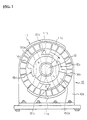
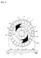
- Figs. 1 to 5 show a first embodiment of a motor of the present invention which is of a single-phase/two-pole type.
- an electromagnet 11 constituting a stator is mounted between front and rear side plates 10a of a supporting member 10.
- the electromagnet 11 includes a cylindrical iron core 11a having 24 pieces of slots, and 12 sets of coils 11b wound around the iron core 11a.
- the electromagnet 11 generates a rotating magnetic field when being applied with a three-phase alternating current.
- Such a rotating magnetic field is distributed, as shown in Fig. 4, within a plane vertical to a rotation output shaft 12 (described later), and it is rotated, for example, clockwise in Fig. 1.
- the above-described rotation output shaft 12 is rotatably mounted through a bearing 13 between the front and rear side plates 10a of the supporting member 10 in a rotating magnetic field of the electromagnet 11.
- Semi-cylindrical permanent magnetic 14a, 14b are disposed around the outer periphery of the rotation output shaft 12 in such a manner as to surround the rotation output shaft 12. As shown in Figs. 1 and 3, one permanent magnet 14a is magnetized in an N-pole reversed to one magnetic pole (S pole) of the rotating magnetic field, while the other permanent magnet 14b is magnetized in an S-pole reversed to the other magnetic pole (N-pole) of the rotating magnetic field.
- the magnetic field produced by the permanent magnets 14a, 14b combined with each other in a cylindrical shape is distributed within a plane vertical to the rotation output shaft 12 like the rotating magnetic field of the electromagnet 11.
- the magnetic intensity of the magnetic field produced by the permanent magnets 14a, 14b can be freely set irrespective of the magnetic intensity of the rotating magnetic field of the electromagnet 11.
- a magnetic body 15a is disposed outside the permanent magnet 14a in such manner as to surround the permanent magnet 14a, while a magnetic body 15b is disposed outside the permanent magnet 14b in such a manner as to surround the permanent magnet 14b.
- a magnetic flux of the permanent magnets 14a, 14b passes through the magnetic bodies 15a, 15b.
- the wall thickness of each of the magnetic bodies 15a, 15b is set at such a value that the magnetic flux can be converged in a specified direction when a rotating magnetic field is generated from the electromagnet 11.
- each of the magnetic bodies 15a, 15b is thinner than the above set value, for example, if it is set at a value nearly equal to a wall thickness of a mild magnetic body provided in a common hybrid type motor, it becomes impossible to achieve the convergence effect of the magnetic flux.
- Magnetic tooth portions 150a, 150b are respectively integrated with the outer peripheral portions of the magnetic bodies 15a, 15b in such a manner as to radially project therefrom.
- Each of the magnetic tooth portions 150a, 150b has a width nearly equal to that of the rotating magnetic field of the electromagnet 11.
- the magnetic bodies 15a, 15b are not connected to each other but are spaced apart from each other at an interval as shown in Fig. 1.
- the permanent magnets 14a, 14b and the magnetic bodies 15a, 15b are coaxially mounted outside the rotation output shaft 12, and constitute a rotor which is attracted by the rotating magnetic field in the rotating magnetic field of the electromagnet 11 and is rotated together with the rotation output shaft 12.
- the electromagnet 11 generates a single rotating magnetic field, and is operated with two poles.
- One end portion of each of the magnetic tooth portions 150a, 150b, that is, each of the end portions 151a, 151b, in the rotating direction, of the rotor is set at an acute angle, in order that when the magnetic flux of the permanent magnets 14a, 14b passing through the magnetic bodies 15a, 15b is converged on the rotating magnetic field side, a large rotating torque is produced, that is, the inclination of the magnetic line of force in an interval between the magnetic tooth portions 150a, 150b and the iron core lla of the electromagnet 11 is increased.
- a rotating torque can be effectively obtained upon start of the motor.
- Each of the magnetic bodies 15a, 15b may be made of an iron material, or a magnetic material having a high permeability such as a silicon steel plate or permalloy; however, in this embodiment, it is made of a mild magnetic material.
- the rotor instantly comes to a synchronous state, and is transferred to a synchronous operating state, that is, a state operated by the rotating torque generated depending on a load angle ⁇ between a magnetic axis of the rotating magnetic field and that of the rotor.
- the magnetic body was formed of mild steel in a shape shown in Fig. 1.
- the permanent magnet was made of a samarium containing cobalt alloy (SmCo).
- the magnetic intensity of the permanent magnet was 12,000 gauss.
- a commercial induction motor for example, a three-phase induction motor, Hitachi "TFO-OK” (maximum output: 310 W) was used as the electromagnet.
- the revolution speed of the motor was measured using a digital tachometer, "HT-4100" by Ono Sokki.
- the size of the motor can be significantly reduced.
- a rotating torque is proportional to the intensities of the rotating magnetic field of the electromagnet 11 and the magnetic field of the permanent magnets 14a, 14b, a high torque can be obtained by the use of permanent magnets with a high magnetic intensity.
- the magnetic bodies may be mounted on the rotation output shaft 12 in such a manner as to be eccentric thereto.
- the magnetic flux of the permanent magnets can be converged without provision of the magnetic tooth portions, to obtain a rotating torque upon start of rotation.
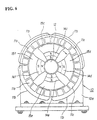
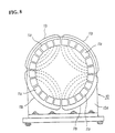
- FIG. 6 A second embodiment of the present invention will be described with reference to Figs. 6 to 9.
- a motor of a three-phase/four-pole type is used.
- parts corresponding to those shown in Figs. 1 to 5 are indicated by the same reference characters, and the explanation thereof is omitted.
- coils 11b are wound around a cylindrical iron core 11a having 24 pieces of slots.
- a rotating magnetic field within a plane vertical to a rotation output shaft 12 as shown in Fig. 8 is generated.
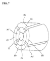
- Four permanent magnets 14c to 14f are disposed around the rotation output shaft 12.
- Each of the permanent magnets 14c to 14f is made of a permanent magnet material such as a samarium containing cobalt alloy (SmCo) or ferrite, and it is magnetized in a polarity reversed to that of the rotating magnetic field.
- SmCo samarium containing cobalt alloy
- the outside (the electromagnetic 11 side) is magnetized in an N-pole and the inside (the rotation output shaft 12 side) is magnetized at an S pole; while in the case of the permanent magnets 14d and 14f, the outside (the electromagnet 11 side) is magnetized in the S-pole and the inside (the rotation output shaft 12 side) is magnetized in the N-pole.
- the magnetic fields produced by the permanent magnets 14c to 14f are distributed in a plane vertical to the rotation output shaft 12 like the rotating magnetic field of the electromagnet 11.
- the magnetic intensity of each of the permanent magnets 14c to 14f can be freely set irrespective of the magnetic intensity of a rotating magnetic field produced by the electromagnet 11.
- Magnetic bodies 15c to 15f are provided outside the permanent magnets 14c to 14f, respectively.
- Each of the magnetic bodies 15c to 15f is made of an iron material or a magnetic material having a high permeability such as a silicon steel plate or permalloy.
- a magnetic flux of the permanent magnets 14c to 14f passes through the magnetic bodies 15c to 15f.
- the wall thickness of each of the magnetic bodies 15c to 15f is set at such a value that the magnetic flux is allowed to be converged in a specified direction.
- the wall thickness of the magnetic body is set to be in a range of from 10 mm to 15 mm.
- the permanent magnets 14c to 14f and the magnetic bodies 15c to 15f constitute a rotor which is attracted by the rotating magnetic field in the rotating magnetic field of the electromagnet 11 and is rotated together with the rotation output shaft 12.
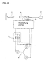
- Fig. 10 schematically shows an apparatus used in the operating test.
- reference numeral 16 indicates a three-phase power source variable in frequency and voltage, KIKUSUI "PCR500L” and “3P02-PCR-L”; 17 is a power factor means YOKOGAWA "67AR0228"; 18 is a pulley (diameter: 60 mm ⁇ ) fixed on the rotation output shaft 12 of a prototype motor of the second embodiment; 19 is a spring balancer by KAMOSHITA SEIKOUSHO (applicable range: 2 kg to 5 kg); and 20 is a weight.
- a tachometer, ONO SOKKI "HT-4100” was used.
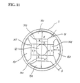
- Fig. 11 shows the cross-section of the prototype motor.
- the motor case and the stator of the motor was diverted from those of a commercial induction motor of a three-phase/four-pole type (200 V, 100 W).
- the motor case has dimensions: 124.5 mm (axial length), and 115.5 mm (outside diameter).
- the stator has dimensions: 40 mm ( axial length); 111.7 mm (outside diameter); and 67.5 mm (inside diameter).
- the diameter of the rotation output shaft 12 is 17.5 mm ⁇ .
- a permanent magnet, SUMITOMO Metal Industries, Ltd. "NEOMAX-40" was used as each of the permanent magnets 14c to 14f.
- Each of the permanent magnets 14c to 14f has a size of 10 mm (thickness) ⁇ 20 mm (width) ⁇ 40 mm (length).
- the following five kinds of prototype motors were prepared. No. 1 Motor diameter "d” of rotor 66 mm ⁇ interval “s” between magnetic bodies 5 mm thickness "t” of magnetic body 10 mm interval “w” between rotor and stator 0.5 mm No. 2 Motor diameter "d” of rotor 66 mm ⁇ interval “s” between magnetic bodies 10 mm thickness "t” of magnetic body 13 mm interval "w” between rotor and stator 0.5 mm No.
- a phase voltage (V), a phase current (A), a power factor (COS), a revolution speed (RPM), and a torque (kg ⁇ cm) were measured.
- a frequency and a voltage of the three-phase power source 16, and a magnitude of the weight 20 were varied.
- the operating test was carried out under the condition that the weight (load) was set at 3.5 kg; the frequency was changed in a range of from 50 to 60 Hz; and the input voltage was changed in a range of from 100 V to 115 V.
- Table 1 For comparison, the above common induction motor of a three-phase/four-pole type was tested in the same condition. The results are shown in Table 2.
- the motor of this embodiment is higher than the common induction motor in input-output ratio (efficiency). Namely, the input-output ratio in the motor of this embodiment is higher than 80%.
- the input-output ratio (efficiency) is more than or equal to 80%.
- an interval between the stator and the rotor is not equalized, but is slightly widened on the end portion side, in the rotating direction, of the magnetic body.
- an input-output ratio (efficiency) depending on a wall thickness (5 mm and 16 mm) of the magnetic body was examined under the condition that the weight (load) was set at 3.5 kg, the frequency was set at 50 Hz and the input voltage was set at 115 V (line voltage: 200 V).
- the results are shown in Fig. 12.
- the input-output ratio (efficiency) is changed depending on a wall thickness of the magnetic body. For example, in this test, an input-output ratio of 98% was obtained when the wall thickness of the magnetic body was set at around 13 mm.
- the relationship between a phase voltage (V) and an output torque (kg ⁇ cm) was also obtained.
- the results are shown in Fig. 13.
- a high torque can be obtained even at a low speed operation (15 kg ⁇ cm for 5 Hz; and 20 kg ⁇ cm for 10 Hz), and consequently, the motor allows continuous variable transmission using an invertor.
- the input-output ratio (efficiency) is varied depending on a load, a frequency, an input voltage and the like, so that energy saving can be significantly improved by adjusting these operating factors under fuzzy control and usually operating the motor at the maximum efficiency in accordance with a variable load.
- the present invention is not limited to the single-phase/two-pole motor shown in the first embodiment and to the three-phase/four-pole motor shown in the second embodiment, but it may be also applied to a multi-phase/multi-pole motor.
- the motor of the present invention allows self-starting without provision of any squirrel-cage rotor, and thereby it can be reduced in size.
- the energy efficiency can be easily increased up to 80% or more in accordance with the operating condition.
- a high torque can be obtained by the use of a permanent magnet with a high magnetic intensity.
Landscapes
- Engineering & Computer Science (AREA)
- Power Engineering (AREA)
- Permanent Magnet Type Synchronous Machine (AREA)
- Iron Core Of Rotating Electric Machines (AREA)
Description
| No. 1 Motor | |
| diameter "d" of rotor | 66 mm |
| interval "s" between | 5 mm |
| thickness "t" of | 10 mm |
| interval "w" between rotor and stator | 0.5 mm |
| No. 2 Motor | |
| diameter "d" of rotor | 66 mm |
| interval "s" between | 10 mm |
| thickness "t" of | 13 mm |
| interval "w" between rotor and stator | 0.5 mm |
| No. 3 Motor | |
| diameter "d" of rotor | 66 mm |
| interval "s" between | 8 mm |
| thickness "t" of | 5 mm |
| interval "w" between rotor and stator | 0.5 mm |
| No. 4 Motor | |
| diameter "d" of rotor | 66.3 mm |
| interval "s" between | 6 mm |
| thickness "t" of | 13 mm |
| interval "w" between rotor and stator | 0.35 mm |
| No. 5 Motor | |
| diameter "d" of rotor | 66 mm |
| interval "s" between | 7 mm |
| thickness "t" of | 10 mm |
| interval "w" between rotor and stator | 0.5 mm |
| LOAD | I N P U T | O U T P U T | |||||||
| Kg | Hz | V | A | COS | W | RPM | Kg-cm | W | % |
| 3.5 | 50 | 100 | 0.54 | 0.99 | 160.4 | 1500 | 8.55 | 131.7 | 82.0 |
| " | 50 | 110 | 0.45 | 0.90 | 134.0 | 1500 | 7.05 | 109.0 | 81.3 |
| " | 50 | 115 | 0.51 | 0.83 | 146.0 | 1500 | 7.65 | 118.0 | 80.8 |
| " | 50 | 115 | 0.55 | 0.88 | 167.0 | 1500 | 9.00 | 138.6 | 83.0 |
| " | 53 | 115 | 0.51 | 0.97 | 170.7 | 1590 | 9.00 | 146.9 | 86.0 |
| " | 55 | 100 | 0.68 | 0.90 | 183.6 | 1650 | 8.70 | 146.9 | 80.0 |
| " | 55 | 110 | 0.48 | 0.99 | 158.0 | 1650 | 7.65 | 129.0 | 81.6 |
| " | 55 | 115 | 0.45 | 0.97 | 150.0 | 1650 | 7.50 | 127.0 | 84.7 |
| " | 55 | 115 | 0.53 | 0.99 | 181.0 | 1650 | 9.00 | 152.5 | 84.0 |
| " | 60 | 100 | 0.68 | 0.75 | 193.5 | 1800 | 8.70 | 161.0 | 83.0 |
| " | 60 | 115 | 0.60 | 0.97 | 200.8 | 1800 | 9.00 | 166.3 | 83.0 |
| LOAD | I N P U T | O U T P U T | |||||||
| Kg | Hz | V | A | COS | W | RPM | Kg-cm | W | % |
| 3.0 | 50 | 105 | 0.77 | 0.74 | 179.5 | 1403 | 8.70 | 125.3 | 69.8 |
| " | 50 | 115 | 0.79 | 0.68 | 185.3 | 1421 | 8.85 | 129.1 | 69.7 |
| " | 50 | 100 | 0.77 | 0.77 | 177.0 | 1395 | 8.85 | 127.0 | 71.0 |
| " | 55 | 100 | 0.80 | 0.80 | 192.0 | 1518 | 8.85 | 138.0 | 71.8 |
| " | 60 | 100 | 0.86 | 0.85 | 219.0 | 1633 | 8.85 | 148.0 | 67.0 |
| " | 50 | 115 | 0.77 | 0.68 | 181.0 | 1422 | 8.85 | 131.0 | 72.0 |
| " | 55 | 115 | 0.78 | 0.74 | 199.0 | 1551 | 8.85 | 143.0 | 71.0 |
| " | 60 | 115 | 0.79 | 0.78 | 212.0 | 1675 | 8.85 | 152.0 | 71.0 |
| LOAD | I N P U T | O U T P U T | |||||||
| Kg | Hz | V | A | COS | W | RPM | Kg-cm | W | % |
| 3.0 | 45 | 90 | 0.47 | 0.97 | 123.1 | 1350 | 6.30 | 87.3 | 70.9 |
| " | " | 95 | 0.43 | 0.97 | 118.9 | " | " | " | 73.4 |
| " | " | 100 | 0.47 | 0.78 | 110.0 | " | " | " | 79.4 |
| " | " | 105 | 0.61 | 0.62 | 119.4 | " | " | " | 73.4 |
| " | " | 110 | 0.77 | 0.58 | 147.4 | " | " | " | 59.2 |
| " | " | 115 | 0.92 | 0.52 | 165.0 | " | " | " | 52.9 |
| 2.5 | 50 | 95 | 0.48 | 0.80 | 112.0 | 1500 | 6.30 | 97.0 | 86.6 |
| " | " | 100 | 0.38 | 0.99 | 113.0 | " | " | " | 85.8 |
| " | " | 105 | 0.37 | 0.96 | 112.0 | " | " | " | 86.6 |
| " | " | 110 | 0.45 | 0.76 | 113.5 | " | " | " | 85.8 |
| 2.5 | 55 | 105 | 0.43 | 0.90 | 122.0 | 1650 | 6.30 | 106.7 | 87.5 |
| " | " | 110 | 0.35 | 0.90 | 115.1 | " | " | " | 92.8 |
| " | " | 115 | 0.38 | 0.96 | 125.9 | " | " | " | 84.7 |
| LOAD | I N P U T | O U T P U T | |||||||
| Kg | Hz | V | A | COS | W | RPM | Kg-cm | W | % |
| 3.0 | 50 | 110 | 0.47 | 0.90 | 139.0 | 1500 | 7.20 | 105.0 | 75.0 |
| " | " | 115 | 0.53 | 0.77 | 141.0 | " | " | 111.0 | 76.0 |
| " | 55 | 110 | 0.46 | 0.99 | 151.0 | 1650 | " | 122.0 | 80.8 |
| " | " | 115 | 0.46 | 0.98 | 155.0 | " | 7.35 | 125.0 | 80.6 |
| LOAD | I N P U T | O U T P U T | |||||||
| Kg | Hz | V | A | COS | W | RPM | Kg-cm | W | % |
| 3.0 | 50 | 110 | 0.45 | 0.98 | 140.0 | 1500 | 7.65 | 118.0 | 84.2 |
| " | " | 115 | 0.48 | 0.88 | 146.0 | " | 7.65 | 118.0 | 80.8 |
| " | 55 | 110 | 0.50 | 0.96 | 158.0 | 1650 | 7.50 | 127.0 | 80.3 |
| " | " | 115 | 0.45 | 0.99 | 154.0 | " | 7.35 | 124.0 | 80.5 |
| 3.5 | 50 | 100 | 0.54 | 0.95 | 154.0 | 1500 | 8.25 | 127.0 | 82.0 |
| " | " | 105 | 0.48 | 0.99 | 150.0 | " | " | " | 85.0 |
| " | " | 110 | 0.47 | 0.98 | 152.0 | " | " | " | 84.0 |
| " | " | 115 | 0.51 | 0.90 | 177.0 | " | " | " | 72.0 |
| 3.5 | 55 | 100 | 0.70 | 0.84 | 176.0 | 1650 | 8.25 | 140.0 | 79.5 |
| " | " | 105 | 0.66 | 0.90 | 187.0 | " | 8.85 | 150.0 | 80.0 |
| " | " | 110 | 0.63 | 0.96 | 199.5 | " | 9.00 | 152.0 | 76.0 |
| " | " | 115 | 0.60 | 0.99 | 206.0 | " | 9.30 | 158.0 | 77.0 |
| " | " | 115 | 0.54 | 0.99 | 185.0 | " | 9.15 | 155.0 | 84.0 |
| LOAD | I N P U T | O U T P U T | |||||||
| Kg | Hz | V | A | COS | W | RPM | Kg-cm | W | % |
| 3.6 | 50 | 115 | 0.47 | 0.74 | 119.9 | 1500 | 6.30 | 97.0 | 80.0 |
| " | " | 115 | 0.47 | 0.86 | 139.0 | " | 8.85 | 136.0 | 98.0 |
| " | " | 115 | 0.51 | 0.93 | 160.0 | " | 9.15 | 141.0 | 86.0 |
| " | " | 115 | 0.52 | 0.92 | 165.0 | " | 9.00 | 139.0 | 84.0 |
| " | " | 115 | 0.49 | 1.00 | 169.0 | " | 9.30 | 143.0 | 85.0 |
| LOAD | I N P U T | O U T P U T | |||||||
| Kg | Hz | V | A | COS | W | RPM | Kg-cm | W | % |
| 2.5 | 40 | 80 | 0.45 | 0.97 | 105.0 | 1200 | 6.45 | 79.0 | 75.2 |
| " | " | 100 | 0.64 | 0.65 | 124.8 | " | 6.15 | 75.8 | 60.7 |
| 3.7 | " | 100 | 0.66 | 0.81 | 160.0 | " | 9.15 | 113.0 | 70.6 |
| 4.5 | " | 105 | 0.76 | 0.79 | 189.0 | " | 11.55 | 142.0 | 75.1 |
| 2.5 | 45 | 105 | 0.53 | 0.85 | 93.7 | 1350 | 7.20 | 93.7 | 100.0 |
| 2.6 | 40 | 80 | 0.33 | 0.99 | 78.4 | 1200 | 6.90 | 78.4 | 100.0 |
| 3.7 | " | 90 | 0.53 | 0.95 | 136.0 | " | 9.45 | 116.0 | 85.3 |
| 4.8 | " | 100 | 0.69 | 0.86 | 178.0 | " | 11.10 | 137.0 | 76.9 |
| 4.3 | " | 110 | 0.87 | 0.70 | 201.0 | " | 11.25 | 139.0 | 69.1 |
Claims (10)
- A power generator for converting a magnetic energy into a motive power, comprising:an electromagnet (11) for generating a rotating magnetic field by an alternating current applied to a coil of said electromagnet, said electromagnet being fixed on a supporting member (10);a rotation output shaft (12) rotatably supported on said supporting shaft in such a manner as to be positioned in said rotating magnetic field;a permanent magnet (14a,14b;14c,14d,14e,14f) disposed around said rotation output shaft in such a manner that a polarity of said permanent magnet is reversed to that of said rotating magnet field, said permanent magnet being rotated together with said rotation output shaft; anda plurality of magnetic bodies (15a,15b;15c,15d,15e,15f) disposed outside said permanent magnet in such a manner as to be rotated together with said rotation output shaft;wherein each of said magnetic bodies has a magnetic tooth portion (150a,150b) formed on the outer periphery thereof;a magnetic flux of said permanent magnet passes through said magnetic bodies;a wall thickness of each of said magnetic bodies is set in such a value that when said electromagnet (11) is excited, said magnetic flux is converged on a side of said rotating magnetic field in said magnetic body; andwhen said electromagnet is excited, said magnetic flux is rotated together with said rotating magnetic field, whereby said rotation output shaft (12) receives a rotating torque.
- A power generator according to claim 1, wherein a width, in the circumferential direction, of said magnetic tooth portion (150a,150b) of said magnetic body is nearly equal to a width of said rotating magnetic field.
- A power generator according to claim 2, wherein an end portion, in the rotating direction, of said magnetic tooth portion (150a,150b) is formed in a shape inclined at an acute angle.
- A power generator according to any of claims 1 to 3, wherein an interval is provided between adjacent ones of a plurality of said magnetic bodies (15a-15f) disposed outside of said permanent magnet (14a-14f).
- A power generator according to any of claims 1 to 4, wherein said permanent magnet(14a-14f) is made of a samarium containing cobalt alloy having a magnetic intensity of 12,000 gauss.
- A power generator according to any of claims 1 to 5, wherein each of said magnetic bodies (15a-15f) is mounted in such a manner as to eccentric to said rotation output shaft (12).
- A power generator according to any of claims 1 to 5, wherein said electromagnet (11) is of a single-phase/two-pole type.
- A power generator according to any of claims 1, 3, 4 or 5, wherein said electromagnet (11) is of a three-phase/four-pole type.
- A power generator according to claim 8, wherein a wall thickness of each of said magnetic bodies (15a-15f) is set to be within a range of from 10 mm to 15 mm.
- A power generator according to any of claims 1, 3, 4 or 5, wherein an interval between said electromagnet (11) and each of said magnetic bodies (15a-15f) is formed to be wider on an end portion side, in the rotating direction, of the magnetic body than on the other portion.
Applications Claiming Priority (5)
| Application Number | Priority Date | Filing Date | Title |
|---|---|---|---|
| JP146532/93 | 1993-06-17 | ||
| JP14653293 | 1993-06-17 | ||
| JP251910/93 | 1993-10-07 | ||
| JP25191093 | 1993-10-07 | ||
| PCT/JP1994/000970 WO1995000995A1 (en) | 1993-06-17 | 1994-06-16 | Power generating device |
Publications (3)
| Publication Number | Publication Date |
|---|---|
| EP0762600A1 EP0762600A1 (en) | 1997-03-12 |
| EP0762600A4 EP0762600A4 (en) | 1997-08-20 |
| EP0762600B1 true EP0762600B1 (en) | 1998-08-19 |
Family
ID=26477346
Family Applications (1)
| Application Number | Title | Priority Date | Filing Date |
|---|---|---|---|
| EP94918528A Expired - Lifetime EP0762600B1 (en) | 1993-06-17 | 1994-06-16 | Power generating device |
Country Status (5)
| Country | Link |
|---|---|
| US (1) | US5719458A (en) |
| EP (1) | EP0762600B1 (en) |
| KR (1) | KR100339437B1 (en) |
| DE (1) | DE69412648T2 (en) |
| WO (1) | WO1995000995A1 (en) |
Families Citing this family (22)
| Publication number | Priority date | Publication date | Assignee | Title |
|---|---|---|---|---|
| US6087751A (en) * | 1997-07-01 | 2000-07-11 | Kabushiki Kaisha Toshiba | Reluctance type rotating machine with permanent magnets |
| US6849984B2 (en) * | 1998-10-13 | 2005-02-01 | Raymond Joseph Gallant | Magnetically driven wheel for use in radial/rotary propulsion system having an energy recovery feature |
| US7105972B2 (en) * | 1998-10-13 | 2006-09-12 | Gallant Raymond J | Controller and magnetically driven wheel for use in a radial/rotary propulsion system |
| US20040070300A1 (en) * | 2002-10-10 | 2004-04-15 | Fu Zhenxing (Zack) | Low torque ripple surface mounted magnet synchronous motors for electric power assisted steering |
| US7382072B2 (en) * | 2003-05-22 | 2008-06-03 | Erfurt & Company | Generator |
| JP4791013B2 (en) * | 2004-07-22 | 2011-10-12 | 三菱電機株式会社 | Brushless motor |
| US7081696B2 (en) | 2004-08-12 | 2006-07-25 | Exro Technologies Inc. | Polyphasic multi-coil generator |
| CA2487668C (en) * | 2004-08-12 | 2013-03-26 | Dpm Technologies Inc. | Polyphasic multi-coil device |
| CA2654462A1 (en) | 2006-06-08 | 2007-12-13 | Exro Technologies Inc. | Poly-phasic multi-coil generator |
| EP2073359A1 (en) * | 2007-12-20 | 2009-06-24 | SycoTec GmbH & Co. KG | Tube motor |
| ATE513349T1 (en) * | 2007-12-20 | 2011-07-15 | Sycotec Gmbh & Co Kg | ELECTRIC MOTOR WITH MEDIA LINE THROUGH THE STATOR |
| US8143738B2 (en) * | 2008-08-06 | 2012-03-27 | Infinite Wind Energy LLC | Hyper-surface wind generator |
| US8865356B2 (en) * | 2012-01-11 | 2014-10-21 | Fuelcell Energy, Inc. | Electrical generation system and method for a hybrid fuel cell power plant |
| JP5985067B2 (en) * | 2013-09-17 | 2016-09-06 | 三菱電機株式会社 | Rotating electric machine and elevator hoisting machine |
| RU2674465C2 (en) * | 2017-04-18 | 2018-12-11 | федеральное государственное бюджетное образовательное учреждение высшего образования "Алтайский государственный технический университет им. И.И. Ползунова" (АлтГТУ) | Source of direct current, installed on synchronous step engine, with increased output power |
| RU2667660C1 (en) * | 2017-04-18 | 2018-09-24 | федеральное государственное бюджетное образовательное учреждение высшего образования "Алтайский государственный технический университет им. И.И. Ползунова" (АлтГТУ) | Sine cosine two-phase generator |
| RU2674466C2 (en) * | 2017-04-18 | 2018-12-11 | федеральное государственное бюджетное образовательное учреждение высшего образования "Алтайский государственный технический университет им. И.И. Ползунова" (АлтГТУ) | Source of direct current, installed on synchronous step engine, with increased voltage |
| JP2020521418A (en) | 2017-05-23 | 2020-07-16 | ディーピーエム テクノロジーズ インク. | Variable coil connection system |
| WO2020047663A1 (en) | 2018-09-05 | 2020-03-12 | Dpm Technologies Inc. | Systems and methods for intelligent energy storage and provisioning using an energy storage control system |
| WO2020215154A1 (en) | 2019-04-23 | 2020-10-29 | Dpm Technologies Inc. | Fault tolerant rotating electric machine |
| WO2022232904A1 (en) | 2021-05-04 | 2022-11-10 | Exro Technologies Inc. | Battery control systems and methods |
| CN117337545A (en) | 2021-05-13 | 2024-01-02 | Exro技术公司 | Method and device for driving coils of polyphase motors |
Family Cites Families (17)
| Publication number | Priority date | Publication date | Assignee | Title |
|---|---|---|---|---|
| US3849213A (en) * | 1966-09-01 | 1974-11-19 | M Baermann | Method of producing a molded anisotropic permanent magnet |
| US3676764A (en) * | 1971-01-29 | 1972-07-11 | Kohler Co | Brushless alternating current generator |
| JPS4962112U (en) * | 1972-09-13 | 1974-05-31 | ||
| US3898599A (en) * | 1974-05-09 | 1975-08-05 | Raytheon Co | Toroidal magnetic device |
| JPS5287603A (en) * | 1976-01-16 | 1977-07-21 | Hitachi Metals Ltd | Magnet rotor |
| JPS54135618U (en) * | 1978-03-14 | 1979-09-20 | ||
| JPS55162377U (en) * | 1979-05-09 | 1980-11-21 | ||
| US4404484A (en) * | 1981-03-06 | 1983-09-13 | Tri-Tech, Inc. | Electric rotating machine |
| US4565938A (en) * | 1983-06-13 | 1986-01-21 | Intra-Technology Associates, Inc. | Permanent magnet rotor toroidal generator and motor |
| DE3673086D1 (en) * | 1985-05-24 | 1990-09-06 | Philips Patentverwaltung | SINGLE-PHASE SYNCHRONOUS MOTOR WITH A BIPOLAR, PERMANENTLY MAGNETICALLY EXCITED ROTOR. |
| US4749933A (en) * | 1986-02-26 | 1988-06-07 | Ben Aaron Max | Polyphase induction motor system and operating method |
| DE3640609A1 (en) * | 1986-11-27 | 1988-06-09 | Erwin Sander Elektroapparateba | Permanent-magnet rotor for a single-phase synchronous motor |
| JPS63138866U (en) * | 1987-03-03 | 1988-09-13 | ||
| JPS645348A (en) * | 1987-06-25 | 1989-01-10 | Fuji Electrochemical Co Ltd | Permanent magnet rotor for stepping motor |
| JPH01101166U (en) * | 1987-12-25 | 1989-07-07 | ||
| JPH02184258A (en) * | 1988-12-28 | 1990-07-18 | Bitsugu:Kk | Power generating device |
| JPH05501194A (en) * | 1989-07-27 | 1993-03-04 | アライド・シグナル・インコーポレーテツド | torque coupling device |
-
1994
- 1994-06-16 US US08/569,208 patent/US5719458A/en not_active Expired - Fee Related
- 1994-06-16 WO PCT/JP1994/000970 patent/WO1995000995A1/en not_active Ceased
- 1994-06-16 EP EP94918528A patent/EP0762600B1/en not_active Expired - Lifetime
- 1994-06-16 DE DE69412648T patent/DE69412648T2/en not_active Expired - Fee Related
- 1994-06-16 KR KR1019950705751A patent/KR100339437B1/en not_active Expired - Fee Related
Also Published As
| Publication number | Publication date |
|---|---|
| EP0762600A4 (en) | 1997-08-20 |
| KR100339437B1 (en) | 2002-11-27 |
| EP0762600A1 (en) | 1997-03-12 |
| HK1014223A1 (en) | 1999-09-24 |
| DE69412648D1 (en) | 1998-09-24 |
| US5719458A (en) | 1998-02-17 |
| DE69412648T2 (en) | 1999-03-11 |
| WO1995000995A1 (en) | 1995-01-05 |
| KR960703284A (en) | 1996-06-19 |
Similar Documents
| Publication | Publication Date | Title |
|---|---|---|
| US5719458A (en) | Power generator with improved rotor | |
| US5723928A (en) | Induction motor and method of adjusting power factor of the same | |
| US4831300A (en) | Brushless alternator and synchronous motor with optional stationary field winding | |
| US6127764A (en) | Electric machine | |
| KR100730762B1 (en) | Low inductance electric machine | |
| US5510662A (en) | Permanent magnet motor | |
| US5168187A (en) | Axial pole stepping motor | |
| US6093992A (en) | Electrical machine with dual excitation, especially a motor vehicle alternator | |
| EP0901710B1 (en) | A self-starting brushless electric motor | |
| EP0261953A2 (en) | Full flux reversal variable reluctance machine | |
| US6097126A (en) | Three-phrase reluctance motor | |
| EP1467471A1 (en) | Generator | |
| US5723921A (en) | Hybrid-type stepping motor | |
| WO2001029956A1 (en) | Low inductance electrical machine for flywheel energy storage | |
| EP1045509A1 (en) | An alternating current machine | |
| US4829205A (en) | Dual-rotary induction motor with stationary field winding | |
| US5059884A (en) | Variable reluctance motor providing holding torque | |
| CN115642768B (en) | Ring magnetic-regulating winding memory motor and magnetic-regulating method | |
| KR102195432B1 (en) | One Body Electric Driving and Electric Power Generating Apparatus | |
| KR100912637B1 (en) | Rotary and electromagnetic machines | |
| GB2271025A (en) | Electric machine | |
| EP0630096B1 (en) | Motive power generating device | |
| HK1014223B (en) | Power generating device | |
| US20050275303A1 (en) | Differential flux permanent magnet machine | |
| JP2796237B2 (en) | Power generator |
Legal Events
| Date | Code | Title | Description |
|---|---|---|---|
| PUAI | Public reference made under article 153(3) epc to a published international application that has entered the european phase |
Free format text: ORIGINAL CODE: 0009012 |
|
| 17P | Request for examination filed |
Effective date: 19960111 |
|
| AK | Designated contracting states |
Kind code of ref document: A1 Designated state(s): DE FR GB NL SE |
|
| A4 | Supplementary search report drawn up and despatched | ||
| AK | Designated contracting states |
Kind code of ref document: A4 Designated state(s): DE FR GB NL SE |
|
| GRAG | Despatch of communication of intention to grant |
Free format text: ORIGINAL CODE: EPIDOS AGRA |
|
| 17Q | First examination report despatched |
Effective date: 19971211 |
|
| GRAG | Despatch of communication of intention to grant |
Free format text: ORIGINAL CODE: EPIDOS AGRA |
|
| GRAG | Despatch of communication of intention to grant |
Free format text: ORIGINAL CODE: EPIDOS AGRA |
|
| GRAH | Despatch of communication of intention to grant a patent |
Free format text: ORIGINAL CODE: EPIDOS IGRA |
|
| GRAH | Despatch of communication of intention to grant a patent |
Free format text: ORIGINAL CODE: EPIDOS IGRA |
|
| GRAA | (expected) grant |
Free format text: ORIGINAL CODE: 0009210 |
|
| AK | Designated contracting states |
Kind code of ref document: B1 Designated state(s): DE FR GB NL SE |
|
| REF | Corresponds to: |
Ref document number: 69412648 Country of ref document: DE Date of ref document: 19980924 |
|
| ET | Fr: translation filed | ||
| REG | Reference to a national code |
Ref country code: GB Ref legal event code: 732E |
|
| PLBE | No opposition filed within time limit |
Free format text: ORIGINAL CODE: 0009261 |
|
| STAA | Information on the status of an ep patent application or granted ep patent |
Free format text: STATUS: NO OPPOSITION FILED WITHIN TIME LIMIT |
|
| 26N | No opposition filed | ||
| REG | Reference to a national code |
Ref country code: FR Ref legal event code: TP |
|
| REG | Reference to a national code |
Ref country code: GB Ref legal event code: IF02 |
|
| PGFP | Annual fee paid to national office [announced via postgrant information from national office to epo] |
Ref country code: FR Payment date: 20020610 Year of fee payment: 9 |
|
| PGFP | Annual fee paid to national office [announced via postgrant information from national office to epo] |
Ref country code: SE Payment date: 20020611 Year of fee payment: 9 |
|
| PGFP | Annual fee paid to national office [announced via postgrant information from national office to epo] |
Ref country code: GB Payment date: 20020612 Year of fee payment: 9 |
|
| PGFP | Annual fee paid to national office [announced via postgrant information from national office to epo] |
Ref country code: DE Payment date: 20020619 Year of fee payment: 9 |
|
| PGFP | Annual fee paid to national office [announced via postgrant information from national office to epo] |
Ref country code: NL Payment date: 20020628 Year of fee payment: 9 |
|
| PG25 | Lapsed in a contracting state [announced via postgrant information from national office to epo] |
Ref country code: GB Free format text: LAPSE BECAUSE OF NON-PAYMENT OF DUE FEES Effective date: 20030616 |
|
| PG25 | Lapsed in a contracting state [announced via postgrant information from national office to epo] |
Ref country code: SE Free format text: LAPSE BECAUSE OF NON-PAYMENT OF DUE FEES Effective date: 20030617 |
|
| PG25 | Lapsed in a contracting state [announced via postgrant information from national office to epo] |
Ref country code: NL Free format text: LAPSE BECAUSE OF NON-PAYMENT OF DUE FEES Effective date: 20040101 Ref country code: DE Free format text: LAPSE BECAUSE OF NON-PAYMENT OF DUE FEES Effective date: 20040101 |
|
| EUG | Se: european patent has lapsed | ||
| GBPC | Gb: european patent ceased through non-payment of renewal fee |
Effective date: 20030616 |
|
| PG25 | Lapsed in a contracting state [announced via postgrant information from national office to epo] |
Ref country code: FR Free format text: LAPSE BECAUSE OF NON-PAYMENT OF DUE FEES Effective date: 20040227 |
|
| NLV4 | Nl: lapsed or anulled due to non-payment of the annual fee |
Effective date: 20040101 |
|
| REG | Reference to a national code |
Ref country code: FR Ref legal event code: ST |