EP0762473A2 - Mass spectrometer and mass spectrometry for analysing compounds contained in a solution - Google Patents
Mass spectrometer and mass spectrometry for analysing compounds contained in a solution Download PDFInfo
- Publication number
- EP0762473A2 EP0762473A2 EP96114339A EP96114339A EP0762473A2 EP 0762473 A2 EP0762473 A2 EP 0762473A2 EP 96114339 A EP96114339 A EP 96114339A EP 96114339 A EP96114339 A EP 96114339A EP 0762473 A2 EP0762473 A2 EP 0762473A2
- Authority
- EP
- European Patent Office
- Prior art keywords
- passage
- capillary
- gases
- mass spectrometer
- liquid
- Prior art date
- Legal status (The legal status is an assumption and is not a legal conclusion. Google has not performed a legal analysis and makes no representation as to the accuracy of the status listed.)
- Granted
Links
- 238000004949 mass spectrometry Methods 0.000 title claims description 66
- 150000001875 compounds Chemical class 0.000 title description 2
- 239000007789 gas Substances 0.000 claims abstract description 210
- 239000007788 liquid Substances 0.000 claims abstract description 122
- 238000005507 spraying Methods 0.000 claims abstract description 38
- 150000002500 ions Chemical class 0.000 claims description 257
- 230000005684 electric field Effects 0.000 claims description 70
- 239000007921 spray Substances 0.000 claims description 67
- 239000012488 sample solution Substances 0.000 claims description 48
- 239000011810 insulating material Substances 0.000 claims description 28
- 238000004458 analytical method Methods 0.000 claims description 26
- 238000002347 injection Methods 0.000 claims description 26
- 239000007924 injection Substances 0.000 claims description 26
- 238000000926 separation method Methods 0.000 claims description 24
- 238000005251 capillar electrophoresis Methods 0.000 claims description 21
- 239000000203 mixture Substances 0.000 claims description 21
- 239000000523 sample Substances 0.000 claims description 21
- 238000001514 detection method Methods 0.000 claims description 11
- 239000000463 material Substances 0.000 claims description 10
- 238000007599 discharging Methods 0.000 claims description 9
- 238000010438 heat treatment Methods 0.000 claims description 8
- 230000001105 regulatory effect Effects 0.000 claims description 8
- 238000005040 ion trap Methods 0.000 claims description 5
- 230000001276 controlling effect Effects 0.000 claims description 2
- 230000001939 inductive effect Effects 0.000 claims 4
- 230000002093 peripheral effect Effects 0.000 abstract 1
- 239000000243 solution Substances 0.000 description 46
- 238000000752 ionisation method Methods 0.000 description 33
- 238000000034 method Methods 0.000 description 29
- 238000004519 manufacturing process Methods 0.000 description 28
- QTBSBXVTEAMEQO-UHFFFAOYSA-N Acetic acid Chemical compound CC(O)=O QTBSBXVTEAMEQO-UHFFFAOYSA-N 0.000 description 18
- OKKJLVBELUTLKV-UHFFFAOYSA-N Methanol Chemical compound OC OKKJLVBELUTLKV-UHFFFAOYSA-N 0.000 description 18
- 238000000132 electrospray ionisation Methods 0.000 description 17
- 238000001819 mass spectrum Methods 0.000 description 17
- 238000010586 diagram Methods 0.000 description 15
- 230000035945 sensitivity Effects 0.000 description 15
- IJGRMHOSHXDMSA-UHFFFAOYSA-N Atomic nitrogen Chemical compound N#N IJGRMHOSHXDMSA-UHFFFAOYSA-N 0.000 description 14
- 239000002253 acid Substances 0.000 description 12
- VYPSYNLAJGMNEJ-UHFFFAOYSA-N Silicium dioxide Chemical compound O=[Si]=O VYPSYNLAJGMNEJ-UHFFFAOYSA-N 0.000 description 10
- DTQVDTLACAAQTR-UHFFFAOYSA-N Trifluoroacetic acid Chemical compound OC(=O)C(F)(F)F DTQVDTLACAAQTR-UHFFFAOYSA-N 0.000 description 8
- 239000005350 fused silica glass Substances 0.000 description 8
- 239000011259 mixed solution Substances 0.000 description 7
- 229910052757 nitrogen Inorganic materials 0.000 description 7
- 239000002904 solvent Substances 0.000 description 6
- 238000011144 upstream manufacturing Methods 0.000 description 6
- 230000008878 coupling Effects 0.000 description 5
- 238000010168 coupling process Methods 0.000 description 5
- 238000005859 coupling reaction Methods 0.000 description 5
- 229910052751 metal Inorganic materials 0.000 description 5
- 239000002184 metal Substances 0.000 description 5
- 102000004169 proteins and genes Human genes 0.000 description 5
- 108090000623 proteins and genes Proteins 0.000 description 5
- 238000009834 vaporization Methods 0.000 description 5
- 230000008016 vaporization Effects 0.000 description 5
- 102000036675 Myoglobin Human genes 0.000 description 4
- 108010062374 Myoglobin Proteins 0.000 description 4
- 230000009467 reduction Effects 0.000 description 4
- 239000011347 resin Substances 0.000 description 4
- 229920005989 resin Polymers 0.000 description 4
- 102000001554 Hemoglobins Human genes 0.000 description 3
- 108010054147 Hemoglobins Proteins 0.000 description 3
- 230000003247 decreasing effect Effects 0.000 description 3
- 238000001704 evaporation Methods 0.000 description 3
- 238000010926 purge Methods 0.000 description 3
- CURLTUGMZLYLDI-UHFFFAOYSA-N Carbon dioxide Chemical compound O=C=O CURLTUGMZLYLDI-UHFFFAOYSA-N 0.000 description 2
- 239000000853 adhesive Substances 0.000 description 2
- 230000001070 adhesive effect Effects 0.000 description 2
- 230000008901 benefit Effects 0.000 description 2
- 238000011109 contamination Methods 0.000 description 2
- 230000000694 effects Effects 0.000 description 2
- 238000001962 electrophoresis Methods 0.000 description 2
- CNKHSLKYRMDDNQ-UHFFFAOYSA-N halofenozide Chemical compound C=1C=CC=CC=1C(=O)N(C(C)(C)C)NC(=O)C1=CC=C(Cl)C=C1 CNKHSLKYRMDDNQ-UHFFFAOYSA-N 0.000 description 2
- 230000007935 neutral effect Effects 0.000 description 2
- 230000008569 process Effects 0.000 description 2
- 239000010453 quartz Substances 0.000 description 2
- 230000035939 shock Effects 0.000 description 2
- 238000009736 wetting Methods 0.000 description 2
- 229910000737 Duralumin Inorganic materials 0.000 description 1
- 108010001267 Protein Subunits Proteins 0.000 description 1
- 239000004809 Teflon Substances 0.000 description 1
- 229920006362 Teflon® Polymers 0.000 description 1
- 239000004411 aluminium Substances 0.000 description 1
- 229910052782 aluminium Inorganic materials 0.000 description 1
- XAGFODPZIPBFFR-UHFFFAOYSA-N aluminium Chemical compound [Al] XAGFODPZIPBFFR-UHFFFAOYSA-N 0.000 description 1
- QVGXLLKOCUKJST-UHFFFAOYSA-N atomic oxygen Chemical compound [O] QVGXLLKOCUKJST-UHFFFAOYSA-N 0.000 description 1
- 239000001569 carbon dioxide Substances 0.000 description 1
- 229910002092 carbon dioxide Inorganic materials 0.000 description 1
- 239000004020 conductor Substances 0.000 description 1
- 239000006185 dispersion Substances 0.000 description 1
- 238000009826 distribution Methods 0.000 description 1
- 230000008020 evaporation Effects 0.000 description 1
- 238000002474 experimental method Methods 0.000 description 1
- 238000004811 liquid chromatography Methods 0.000 description 1
- 238000005259 measurement Methods 0.000 description 1
- 238000012986 modification Methods 0.000 description 1
- 230000004048 modification Effects 0.000 description 1
- 239000001301 oxygen Substances 0.000 description 1
- 229910052760 oxygen Inorganic materials 0.000 description 1
- 108090000765 processed proteins & peptides Proteins 0.000 description 1
- 230000004044 response Effects 0.000 description 1
- 229920006395 saturated elastomer Polymers 0.000 description 1
- 238000001228 spectrum Methods 0.000 description 1
- XLYOFNOQVPJJNP-UHFFFAOYSA-N water Substances O XLYOFNOQVPJJNP-UHFFFAOYSA-N 0.000 description 1
Images


Classifications
-
- G—PHYSICS
- G01—MEASURING; TESTING
- G01N—INVESTIGATING OR ANALYSING MATERIALS BY DETERMINING THEIR CHEMICAL OR PHYSICAL PROPERTIES
- G01N30/00—Investigating or analysing materials by separation into components using adsorption, absorption or similar phenomena or using ion-exchange, e.g. chromatography or field flow fractionation
- G01N30/02—Column chromatography
- G01N30/62—Detectors specially adapted therefor
- G01N30/72—Mass spectrometers
- G01N30/7233—Mass spectrometers interfaced to liquid or supercritical fluid chromatograph
- G01N30/724—Nebulising, aerosol formation or ionisation
- G01N30/7266—Nebulising, aerosol formation or ionisation by electric field, e.g. electrospray
-
- H—ELECTRICITY
- H01—ELECTRIC ELEMENTS
- H01J—ELECTRIC DISCHARGE TUBES OR DISCHARGE LAMPS
- H01J49/00—Particle spectrometers or separator tubes
- H01J49/02—Details
- H01J49/04—Arrangements for introducing or extracting samples to be analysed, e.g. vacuum locks; Arrangements for external adjustment of electron- or ion-optical components
- H01J49/0468—Arrangements for introducing or extracting samples to be analysed, e.g. vacuum locks; Arrangements for external adjustment of electron- or ion-optical components with means for heating or cooling the sample
-
- H—ELECTRICITY
- H01—ELECTRIC ELEMENTS
- H01J—ELECTRIC DISCHARGE TUBES OR DISCHARGE LAMPS
- H01J49/00—Particle spectrometers or separator tubes
- H01J49/02—Details
- H01J49/10—Ion sources; Ion guns
- H01J49/16—Ion sources; Ion guns using surface ionisation, e.g. field-, thermionic- or photo-emission
- H01J49/165—Electrospray ionisation
- H01J49/167—Capillaries and nozzles specially adapted therefor
Definitions
- the present invention relates in general to a mass spectrometer and a mass spectrometry, and more particularly to a mass spectrometer and a mass spectrometry each of which employs an ion source for ionisation of compounds contained in a solution.
- electrospray ionization method in an article of "Electrospray Ion Source. Another Variation on the Free-Jet Theme", The Journal of Physical Chemistry, Vol. 88, No. 20, 1984, pp.4451 to 4459, or U. S. Patent No. 5,130,538.
- a high voltage of 2.5kV or more is applied to a metallic capillary into which the liquid is introduced and a counter electrode (corresponding in position to an inlet port for ions of a mass spectrometer). That is, the high voltage is applied to the liquid.
- the liquid is sprayed in the form of charged droplets through a tip of the capillary into a space in which an electric field is applied between the capillary and an counter electrode (the electrostatic spray phenomenon), thereby producing ions charged positive/negative from the charged droplets.
- the polarity of the charged droplets and the ions matches the polarity of the applied voltage.
- multiply charged ions can be produced, and hence the electrospray ionization method is utilized for analysis of protein or the like in many cases.
- the flow rate of liquid is normally used in the range of 0.001 to 0.01 ml/min.
- the liquid is sprayed in the form of ions and charged droplets through the tip of the capillary into a space in which an electric field is applied between the capillary and the counter electrode (the electrostatic spray phenomenon).
- the electrostatic spray ionization method unlike the electrospray ionization method, gases are caused to flow into the outside of the spraying capillary in order to promote vaporization of the charged droplets.
- the ions are produced utilizing the same electrostatic spray phenomenon, the ion thus produced are the same as those in the case of the electrospray ionization method at all.
- the polarity of the charged droplets and the ions matches that of the applied voltage.
- the flow rate of liquid is used in the range of 0.01 to 1 ml/min and it is larger than that in the electrospray ionization method.
- the flow rate of gas must not exceed 216 m/sec.
- the structure is adopted such that the direction of spraying the liquid is substantially perpendicular to the direction of the gas flow.
- the flow rate of the gas flow is not clear.
- the analysis of the ion of interest is carried out on the basis of a value of m/z which is obtained by dividing the mass m of the ion by the charge number thereof z .
- the mass spectrometer in which the upper limit of the mass range of the mass spectrometry is very high is not suitable for practical use because of its large scale and its high cost. Therefore, in the general mass spectrometer, the upper limit of the mass range of the mass spectrometry is in the range of 1,000 to 2,000 or so in the value of m/z.
- the ions are mainly produced from the fine charged droplets.
- the charged droplets each having high density of electric charge are produced, and hence in the multiply-charged ions each having the charge state number z of 3 or more can be produced. Therefore, even in the case of the material, such as protein, having the giant mass m of several tens of thousands or so, the analysis thereof can be carried out since the value m/z is within the range of the mass spectrometry.
- the above-mentioned prior art relating to the sonic spray ionization method and the above-mentioned fourth prior art show a tendency in which the charged droplets each having low density of electric charge are produced and hence the ions each having the small charge state number are produced. That is, the production and the mass spectrometry of a singly-charged ion and a doubly-charged ion such as peptide can be made possible.
- the high voltage is applied to the liquid, and the ions and the charged droplets are produced on the basis of the electrostatic spray phenomenon.
- the large charged droplets each of which has low density of electric charge and the size of which is on the micron order as well as the fine charged droplets each having high density of electric charge are contained in the droplets which are produced on the basis of the above-mentioned phenomenon.
- the mass of the highly charged droplet is too large as compared with an amount of electric charges thereof, and hence it is difficult to control its movement by application of an electric field or a magnetic field.
- the mass spectrometry is carried out using a quadruple mass spectrometer or a quadruple ion trap mass spectrometer, the large charged droplets reach a detector without mass separation, and hence such droplets are detected in the form of random noises.
- the above-mentioned prior art relating to the ion spray ionization method shows a remarkable tendency that the highly charged droplets are readily produced since the flow rate of the liquid is high.
- the same problem is also applied to the above-mentioned fourth prior art.
- the liquid is sprayed by assistance of the gas flow.
- the spraying portion adopts the structure such that the direction of spraying the liquid is substantially perpendicular to the direction of the gas flow. For this reason, a difference of the flow rate of the gas occurs between the upstream side of the gas flow and the downstream side of the gas flow at a tip of the injection needle through which the liquid is sprayed, and as a result, there arises a problem in dispersion in the droplet size that the size of the droplet becomes larger as the droplet is produced in the more downstream side.
- an electrode an electrode 27 in Fig. 2 of U. S. Patent No. 4,300,044) is constructed by one bar.
- the density of electric charge of the droplet which is produced in a region, in the portion for spraying the liquid, in the vicinity of the electrode is different from the density of electric charge of the droplet which is produced in a region away therefrom.
- the large droplet having low density of electric charge is largely produced.
- the counter gas flow is generated at the inlet port for ions of the mass spectrometer in order to promote vaporization of the droplets, it is impossible to achieve the sufficient vaporization of the droplets.
- the ions are mainly produced from the fine charged droplet. In this connection, it is well known that the efficiency of producing ions is high as the size of the droplet is smaller.
- the efficiency of producing ions from the large charged droplet is so low as to be able to be disregarded.
- the sensitivity of detecting an ion is remarkably reduced by reduction of the intensity of a signal and increase of the noise level.
- the liquid chromatograph/mass spectrometer system or the capillary electrophoresis/mass spectrometer system in which the mixture separating means such as a liquid chromatograph or a capillary electrophoresis system is coupled to the upstream side thereof, since the high voltage is applied to the whole mixture separating means, there is a risk that during handling of the mixture separating means, an operator may get an electric shock in some cases.
- the electric potential of the whole mixture separating means may be set to the ground level when using the system in some cases.
- each of the electrospray ionization method and the ion spray ionization method is a method wherein the voltage is directly applied to the sample solution, and by an electrostatic force occurring between the solution and the electrode of the mass spectrometer, the solution is splayed so as to be ionized. Therefore, there arises a problem that when adding strong acid to the sample solution, since a current is caused to flow through the sample solution, no electrostatic spray phenomenon occurs and hence the ionization of the sample solution is difficult.
- a mass spectrometer employing an ion source including: a passage through which liquid is caused to flow to a predetermined position, at least a part of the passage being made of an insulating material; electric field applying means for applying a voltage to the liquid through the insulating material so as to generate an electric field applied thereto; and spray means for spraying therethrough the solution so as to produce charged gases, the spray means being arranged downstream with respect to the liquid to which the electric field is applied.
- a mass spectrometer including: separation means for separating sample liquid containing a mixture; a passage through which the sample liquid thus separated is caused to flow to a predetermined position, at least a part of the passage being made of an insulating material; electric field applying means for applying a voltage to the sample liquid through the insulating material so as to generate an electric field applied thereto; spray means as a room having a gas supplying unit for supplying gases, a gas supply port for supplying therethrough the gases from the gas supplying unit, an injection port for discharging therethrough the gases, and a holding portion for holding the passage; and analysis means, such as a quadruple mass spectrometer or a quadruple ion trap mass spectrometer, for subjecting the sprayed gases to mass spectrometry so as to analyze the sprayed gases.
- a mass spectrometer including: separation means for separating sample solution containing a mixture; detection means for detecting the characteristics of the separated sample solution; a passage through which the separated sample solution is caused to flow to a predetermined position, at least a part of the passage being made of an insulating material; electric field applying means for applying a voltage to the sample liquid through the insulating material so as to generate an electric field applied thereto; spray means as a room having a gas supplying unit for supplying gases, a gas supply port for supplying therethrough the gases from the gas supplying unit, an injection port for discharging therethrough the gases, and a holding portion for holding the passage; analysis means for subjecting the sprayed gases to mass spectrometry so as to analyze the sprayed gases; and a control unit for controlling both the electric field applying means and the analysis means on the basis of a signal outputted from the detection means.
- a mass spectrometer including: an injection port for spraying therethrough liquid so as to produce multiply-charged ions each being at least triply-charged, a part of or the whole injection port being made of an insulating material; a first electrode arranged in the periphery of the injection port; and a second electrode arranged opposite to the first electrode for generating a uniform electric field between the first electrode and the second electrode.
- a mass spectrometer having mixture separating means coupled thereto including: the mixture separating means for separating mixture; a metallic portion for determining an electric potential of the sample solution separated by the mixture separating means; a passage to which the liquid is supplied; electric field applying means for applying a voltage to the liquid flowing through the passage so as to generate an electric field applied thereto, the means being electrically insulated from the passage; an injection port for spraying therethrough the liquid by an ion source having spray means for spraying the liquid so as to produce charged droplets, so as to produce multiply-charged ions each being at least triply-charged, the injection port being arranged downstream with respect to the liquid to which the electric field is applied, a part of or the whole injection port being made of an insulating material; a first electrode arranged in the periphery of the injection port; and a second electrode arranged opposite to the first electrode for generating a uniform electric field between the first electrode and the second electrode.
- a mass spectrometry wherein multiply-charged ions each being at least triply-charged are produced in a uniform electric field which is generated between a first electrode arranged in the periphery of an injection port for spraying therethrough liquid and a second electrode arranged opposite to the first electrode, and the resultant multiply-charged ions are analyzed by a mass spectrometry unit.
- a mass spectrometry including the steps of: separating liquid; applying an electric field to the liquid which has been separated and is determined with an electric potential thereof; and passing multiply-charged ions each being at least triply-charged through a uniform electric field, which is generated between a first electrode arranged in the periphery of an injection port for spraying therethrough the liquid and a second electrode arranged opposite to the first electrode, so as to supply the multiply-charged ions to a mass spectrometry unit for carrying out mass analysis and also to subject the multiply-charged ions to mass spectrometry to analyze the multiply-charged ions.
- a mass spectrometry including the electric field applying step of changing the polarity of an electric field applied to liquid in correspondence to the polarity of multiply-charged ions each being at least triply-charged which are produced in a uniform electric field generated between a first electrode arranged in the periphery of an injection port for spraying therethrough the liquid and a second electrode arranged opposite to the first electrode.
- a mass spectrometry including: the electric field applying step of changing the polarity of an electric field applied to liquid; and the step of producing multiply-charged ions, each being at least triply-charged and having the polarity varying in correspondence to the polarity of the electric field applied to the liquid, in a uniform electric field which is generated between a first electrode arranged in the periphery of an injection port for spraying therethrough the liquid and a second electrode arranged opposite to the first electrode.
- droplets each being electrically neutral are produced by spraying the liquid. While the positive ions and the negative ions which are substantially equal in the number to each other are contained in the droplet, the distribution of density of the positive and negative ions in the vicinity of the surface of the droplet is remarkably different from that in the central portion of the droplet due to the surface electric potential which is determined on the basis of combination of the droplet and the circumambient gases.
- the fine droplets are separated from the surface of the droplet by the gas flow of the sonic velocity. Since the number of positive ions is different from the number of negative ions in each of those fine droplets, the density of electric charge is low, but the fine droplet is changed positive or negative as a whole.
- the ions are produced on the basis of the process of evaporating ions from the fine charged droplet or the perfect vaporization of the charged droplet.
- the electric field is applied through the electrode arranged in the outside to the liquid which is introduced into the fused-silica capillary in the sonic spray ionization method.
- the density of the positive ions is much higher than the density of the negative ion in the area in the vicinity of the surface of the liquid.
- the droplets which are charged positive when spraying the liquid by assistance of the gas flow are preferentially produced, and hence the sprayed gases are charged positive.
- the positive ions are concentrated on the area in the vicinity of the surface by the Coulomb repulsion.
- the density of electric charge of the charged droplet is higher than the density of electric charge of the charged droplet which is produced by the normal sonic spray ionization method.
- the fine droplets each having the very high density of electric charge are produced.
- the ions are produced on the basis of the process of evaporating ions from the fine droplet or the perfect vaporization of the charged droplet. In the former, the efficiency of producing multiply-charged ions is in general remarkably so low as to be able to be disregarded as compared with that of producing singly charged ions.
- the density of electric charge of the droplet is high, since the Coulomb repulsion in the droplet is remarkably large, the efficiency of producing multiply-charged ions becomes high. For this reason, the multiply-charged ions can also be produced.
- the density of positive or negative ions of the area in the vicinity of the surface of the liquid can be made very high. Therefore, it is meaningless that an electric field is applied to the droplets which have been produced by the spray. It is required that an electric field is applied to the liquid before being sprayed.
- the mass spectrometer and the mass spectrometry of the present invention since the electrostatic spray phenomenon is not utilized for the ion production at all, the ion production is not influenced by the contamination and wetting of the inlet port for ions of the mass spectrometry unit and the spraying capillary at all. Therefore, the system can be readily handled, and the reproducibility of ion production is also high.
- the electric potential of the liquid introduced into the ion source can be set to the ground level.
- the capillary electrophoresis system or the liquid chromatograph can be readily coupled to the portion of the system which is located upstream with respect to the ion source. In this connection, the reproducibility of the ion production is not degraded by this coupling at all.
- a capillary is made of an insulating material such as quartz or resin, and a voltage is applied to a metallic orifice into which a tip of the capillary is inserted.
- a capillary is made of an insulating material, and an outer surface of a portion near a tip of the capillary is coated with metal, and under this condition, a voltage is applied to the outer surface of the capillary.
- an insulating capillary is inserted into a metallic conduit to which a voltage is to be applied.
- the electric field is applied to the solution through the insulating material such as quartz or resin, the voltage is not directly applied to the solution. For this reason, even in the case where strong acid solution is applied to the mass spectrometry, no current is caused to flow through the solution. Further, since the solution is sprayed by assistance of the gas flow, the ion production is not hindered at all.
- Fig. 1 there is shown a schematic view, partly in cross sectional view, of a structure of an ion source according to an embodiment of the present invention.
- Liquid is introduced into a capillary 2 through a passage 1.
- a tip of the capillary 2 is substantially coaxially inserted into an orifice 3.
- Gases which have been supplied from a gas supplying unit 4 are introduced into an ion source body 6 through a gas introducing conduit 5 and then are discharged through the orifice 3 to the outside.
- the orifice 3 is made of metal, and a suitable voltage is applied across the orifice 3 and a metallic conduit 8 by a power source 7.
- FIG. 2 there is shown a cross sectional view, partly in block diagram, of an ion source according to an embodiment of the present invention.
- an electric potential of which is set to the ground level, at a flow rate of 5 to 100 ⁇ l/min
- the liquid is introduced into a fused-silica capillary 2 (its inner diameter is 0.1mm and its outer diameter is 0.2mm).
- An orifice plate 9 through which an orifice 3 (its inner diameter is 0.4mm and its outer diameter is 1.0mm) is bored is made of duralumin, and a suitable voltage is applied to the orifice plate 9 by the power source 7.
- the capillary 2 is inserted into two Teflon conduits 10 and two stainless conduits 11, and is adhered to the stainless conduits 11 by adhesive.
- the liquid is electrically insulated from the ion source body 6 through a space defined between the two stainless conduits 11.
- the central axis of the capillary 2 is substantially aligned with the central axis of the orifice 3, and a tip of the capillary 2 is exposed from the orifice plate 9 to the outside by about 0.2mm.
- the stainless conduits 11 are also used to fix the capillary 2 to the ion source body 6. When the orifice plate 9 is cooled by the adiabatic expansion of the gases, the resultant droplet may coagulate so that it may not become fine in some cases.
- a heater is provided in either the orifice plate 9 or the ion source body 6 in order to heat it, or the gases to be introduced into the ion source is previously heated.
- the gases are introduced into the gas introducing conduit 5 from a gas bomb or a gas compressor.
- a gas flow rate regulating unit such as a mass flow controller or a purge meter is installed in the middle position between the gas bomb or the gas compressor and the gas introducing conduit 5 in order to regulate the flow rate of gas for use in the spraying operation.
- the gas flow rate is just 3 l/min, the flow rate of gas in the vicinity of the tip of the capillary 2 become the sonic velocity.
- the ions are produced from the fine charged droplet with 10nm or less diameter.
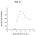
- the fine charged droplets are produced by assistance of the gas spray. While the size of the average droplet which is produced by assistance of the gas spray is decreased as the gas flow rate is further increased, the size of the average droplet is increased when the gas flow rate becomes the supersonic. This results from that the shock wave is generated (refer to Fig. 9). Therefore, the size of the average droplet becomes minimum when the gas flow rate is the sonic velocity, and hence the ion production is most efficiently carried out.
- the efficiency of producing fine droplets is high, and as a result, the efficiency of producing ions is high as a wall thickness of the capillary 2 is smaller.
- an ambient pressure of the ion source is 1 atmosphere and also a thickness of the orifice 3 can be disregarded, the portion located upstream with respect to the orifice 3 requires a gas pressure of about 2 atmospheres.
- the pressure reduction within the orifice 3 can not be disregarded in correspondence to the thickness of the orifice plate 9. If a suitable pressure gage is provided in the ion source body 6 so as to regulate the gas pressure to produce the gas flow of the sonic velocity, this is so convenient.
- the pressure is regulated so as to apply a gas pressure in the range of 0.5 to 5 atmospheres or so to the portion located upstream with respect to the orifice 3.
- gas flow rate regulating means such as a purge meter or a mass flow meter. If the thickness of the orifice 3 is too large, the pressure reduction within the orifice 3 is increased and as a result the pressure within the orifice 3 needs to be unnecessarily increased. There is no need of making the thickness of the orifice 3 larger than a wall thickness of the ion source body 6.
- the thickness of the orifice 3 is set to the range of 0.5 to 1mm which is larger than the diameter of the capillary 2.
- a portion of the ion source body 6 located upstream with respect to the orifice 3 requires a space acting as a gas reservoir so as not to decrease the gas pressure therein. This space requires the size which is 5 or more times as large as that of the diameter of the capillary 2.
- FIG. 3 there is shown a sketch drawing of the ion source according to the embodiment of the present invention shown in Fig. 2.
- the sprayed gases are discharged to this side in the figure.
- a cross section of the ion source body 6 when viewed perpendicularly to the central axis of the capillary 2 is a quadrangle, it may also be made a round shape.
- the orifice plate 9 has four holes bored therethrough in addition to the orifice 3, and the orifice plate 9 is screwed on the ion source body 6 by using four screws corresponding to the four holes.
- the positional adjustment is carried out under the microscope such that the center of the orifice 3 is substantially aligned with the center of the capillary 2, and under this condition, the orifice plate 9 is mounted to the ion source body 6 by the four screws. In such a way, a uniform gas flow is generated at the tip of the capillary 2. From the size in the figure, it is shown that the ion source of the present invention is very compact.
- Fig. 4 there is shown the dependency of the total ion current produced by the spray on a voltage applied to the orifice 3. This is obtained from the experimental results in the case where a solution of 47.5% methyl alcohol/47.5% water/5%acetic acid is used as the sample liquid. From the experimental results, it is shown that when applying a positive voltage to the sample solution, the negative ions and charged droplets are produced, while when applying a negative voltage thereto, the positive ions and charged droplets are produced. That is, it is shown that if applying a voltage of the polarity opposite to the polarity of the ions which are intended to be produced, the ions of the desired polarity are produced.
- a mass spectrum which is obtained from the experimental results in which ions produced when setting the applied voltage to -1kV is subjected to the mass spectrometry. That is, this is obtained from the experimental results in which a solution of cytochrome-C with 1 ⁇ mol/l concentration (a kind of protein, and its molecular weight is about 12,500)(a solvent is 48% methyl alcohol liquid containing 5% acetic acid added thereto) is introduced into the capillary 2 at a flow rate of 30 ⁇ l/min, and the ions which have been obtained by spraying the solution by assistance of the gas flow of the sonic velocity are analyzed using a quadruple mass spectrometer.
- the ion spray ionization method and the electrospray ionization method have been utilized for production of multiply-charged ions.
- the ions are produced from the same cytochrome-C solution as the above-mentioned solution by utilizing the ion spray ionization method, and the resultant ions are detected by the same quadruple mass spectrometer.
- Fig. 6 The axis of ordinate is the same as that in Fig. 5. From Fig. 6, it is shown that with respect to the multiply-charged ions, the same spectrum pattern of the mass spectrum as that in Fig.
- a mass spectrum which is obtained from a myoglobin solution (the concentration is 1 ⁇ mol/l, and a solvent is 48% methyl alcohol containing 5% acetic acid added thereto).
- a mass spectrum which is obtained from a hemoglobin solution (the concentration is 1 ⁇ mol/l, and a solvent is 48% methyl alcohol containing 5% acetic acid added thereto).
- Hemoglobin is a kind of protein with 64,500 molecular weight in which two kinds of sub-units are contained, and for every kind of sub-unit, the two associated sub-units are coupled to each other. In Fig. 8, the mass spectrum of the sub-units is observed.
- Fig. 9 there is shown the dependency of the flow rate F of the sprayed gases on the relative intensity of the 16+ ion in Fig. 5.
- Fig. 2 the ion source of the embodiment shown in Fig. 2. From the graphical representation, the relationship is obtained in which the flow rate of gas is increased along with increase of the flow rate of gas.
- the flow rate of gas corresponds to the sonic velocity (Mach 1) when the flow rate of gas is about 3 l/min, and the flow rate of gas is equal to or lower than Mach 2 when the flow rate of gas is about 7 l/min (refer to the above-mentioned first article of Analytical Chemistry, Vol. 66, No.
- the flow rate of gas may be controlled by regulating the gas flow rate F using the flow rate regulating means.
- an area S of a cross section of a clearance gap defined between the orifice and the capillary when viewed perpendicularly to the capillary is calculated to be 9.4 ⁇ 10 -8 m 2 .
- a ratio of F/S is estimated to be 250 m/sec when F is 1.4 l/min, and it is estimated to be 1,200 m/sec when F is 7 l/min. In this connection, take notice of that the unit of the ratio F/S is velocity, but the ratio F/S is different from the flow rate of gas.
- the flow rate of gas may be controlled by the gas presser within the ion source.
- the production of the ions is started at a pressure of about 1.2 atmospheres.
- Mach about 0.5 is achieved when the gas pressure is 1.2 atmospheres
- Mach 1 is achieved when the gas pressure is 2 atmospheres.
- the gas pressure of 7.2 atmospheres is required for achieving Mach 2.
- the gas pressure of 40 atmospheres is required for achieving Mach 3, and hence in this case, there is a problem in terms of practical use.
- the gas pressure is regulated in the range of 0.5 to 5 atmospheres.
- a diameter of the orifice is 0.4mm, and an outer diameter of the fused-silica capillary is 0.2mm. Therefore, the area S of the cross section of the clearance gap defined between the orifice and the capillary is calculated to be 9.4 ⁇ 10 -8 m 2 .
- the parameter F/S is 250m/sec when the flow rate F of gas is 1.4 l/min, and F/S is 530m/sec when F is the sonic velocity (notice needs to be taken of that while the unit of the parameter F/S is velocity, but it has no relation to the actual flow rate of gas).
- the parameter F/S is used in the range of 250 to 1,200m/sec. Since the area S is determined by the structure of the ion source, it is convenient that the flow rate F of gas is regulated using a flow controller such as a mass flow meter or a purge meter.
- the gas flow is used to assist the spray of the liquid. Therefore, the kind of gas does not hardly participate in the ion production. Actually, it is convenient to use nitrogen gases as the gases used to produce the gas flow because nitrogen gases are inexpensive, and also are effective to vaporize the droplets since nitrogen gases are dry. In addition to nitrogen gases, even when using air, oxygen gases, carbon dioxide gases, rare gases, or the like, the same effect can be obtained.
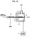
- FIG. 10 there is shown a cross sectional view, partly in block diagram, of an ion source according to another embodiment of the present invention.
- Aluminium is deposited onto an outer surface of a tip with 5mm length of a fused-silica capillary (its inner diameter is 0.01mm, and its outer diameter is 0.05mm), and a suitable voltage is applied to the tip of the capillary 2 by a power source 7.
- a voltage applied to an electrode can be set to a lower level than that in the above-mentioned embodiment shown in Fig. 2.
- an electric potential of an ion source body 6 can be set to the ground level, the safety during operation of the system is very high.
- FIG. 11 there is shown a cross sectional view, partly in block diagram, of an ion source according to still another embodiment of the present invention.
- a capillary 2 made of resin is inserted through a tubular electrode 12, and a suitable voltage is applied to the electrode 12 by a power source 7.
- the capillary 2 made of resin is adhered to the tubular electrode 12 by insulating adhesive. If a sufficiently high voltage is applied to the tubular electrode 12, the tubular electrode 12 is not necessarily aligned coaxially with the capillary 2. However, in the case where the tubular electrode 12 is aligned substantially coaxially with the capillary 2, the ion production is carried out with a lower applied voltage.
- the electrode 12 does not need to have necessarily the tubular shape.
- the applied voltage has only to be much lower in the case where the electrode 12 is arranged to this side with respect to the tip of the capillary 2 as compared with the case where the electrode 2 is not arranged to this side with respect to the tip of the capillary 2.
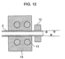
- FIG. 12 there is shown a cross sectional view of an ion source according to yet another embodiment of the present invention.
- a fused-silica capillary 2 is heated by a heating block 14 which is heated in turn by a heater 13. Therefore, the liquid which has been introduced into the capillary 2 is splayed by assistance of heating.
- the droplets which have been produced in the capillary 2 by the spray are charged positive or negative by application of an electric field generated through an electrode 12, thereby producing the charged droplets and the ions.
- an infrared laser or a lamp may be employed.
- FIG. 13 there is shown a cross sectional view of an ion source according to a further embodiment of the present invention.
- the liquid which has been introduced into a fused-silica capillary 2 is sprayed in a transverse direction at a tip of the capillary 2 by assistance of the gas flow which is produced by a gas injection unit 15.
- the positional adjustment of the capillary 2 can be carried out in a very simple manner.
- the present embodiment provides a very simple system for producing charged droplets.
- FIG. 14 there is shown a cross sectional view of an ion source according to an even further embodiment of the present invention.
- the liquid which has been introduced into a fused-silica capillary 2 is converted into droplets by a ultrasonic vibrator 16. These droplets are charged positive or negative when producing the droplets by application of an electric field generated through an electrode 12.
- the sprayed gases charged positive or negative are spatially widely diffused.
- Each of the above-mentioned embodiments shown in Figs. 12 to 14, respectively, has an advantage that the ions can be produced without using either a gas bomb or a compressor.
- FIG. 15 there is shown a cross sectional view, partly in block diagram, of a structure of a mass spectrometer according to an embodiment of the present invention.
- the liquid is introduced into a capillary 2 at a fixed flow rate through a passage 1.
- a tip of the capillary 2 is substantially coaxially inserted into an orifice 3.
- Nitrogen gases which have been supplied from a gas supplying unit 4 are introduced into an ion source body 6 through a gas introducing conduit 5 so as to be discharged through the orifice 3 to the outside.
- a suitable voltage is applied to a metallic orifice plate 9 by a power source 7.
- an electric field is applied to the liquid which has reached the tip of the capillary 2.
- the liquid to which the electric field is applied is sprayed to the outside at an atmospheric pressure by assistance of the gas flow generated through the orifice 3.
- a uniform electric field is present between the metallic orifice plate 9 through which the sprayed gases are produced and an orifice 17 in an inlet port of a mass spectrometry unit 18.
- Both the ions and the charged droplets which have been produced in the sprayed gases are introduced into a vacuum through the orifice 17 in the inlet port of the mass spectrometry unit 18, and then are subjected to the mass separation by application of an electric field or a magnetic field in the mass spectrometry unit 18 installed in a high vacuum unit.
- the ions which have been subjected to the mass separation are detected by an ion detecting unit 19.
- An output signal outputted from ion detecting unit 19 is sent to a computer 20 in order to be analyzed.
- Both the power source 7 and the mass spectrometry unit 18 can be controlled by the computer 20. That is, the positive/negative ions which have been produced on the basis of an intermittent voltage signal generated by the power source 7 can be subjected to the mass separation synchronously with the ion production so as to be detected.
- the positive/negative ions can be analyzed synchronously with the ion production.
- solution separating means such as a capillary electrophoresis system or a liquid chromatograph can be readily coupled to the passage 1.
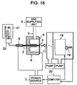
- FIG. 16 there is shown a cross sectional view, partly in block diagram, of a structure of a capillary electrophoresis system/mass spectrometer coupling system of an embodiment of the present invention.
- a mixed solution is introduced into a capillary electrophoresis system 21, and then is electrophoresed by a high voltage applied across mutually-opposite ends of a capillary 2 so as to be separated.
- the separated solution is introduced into the capillary 2 after having been detected in a detection unit 22.
- a tip of the capillary 2 is substantially coaxially inserted into an orifice 2.
- Nitrogen gases which have been supplied from a gas supplying unit 4 are introduced into an ion source body 6 through a gas introducing conduit 5 so as to be discharged through the orifice 3 to the outside in the form of a gas flow.
- An orifice plate 9 is made of metal, and a suitable voltage is applied to the metallic orifice plate 9 by a power source 7.
- the liquid which has reached a tip of the capillary 2 is sprayed to the outside at an atmospheric pressure by assistance of the gas flow.
- Both the ions and the charged droplets which have been produced in the sprayed gases are introduced into a vacuum through an orifice 17 in an inlet port of a mass spectrometry unit, and then are subjected to the mass separation by application of an electric field or a magnetic field in a mass spectrometry unit 18 installed in a high vacuum unit.
- the ions which have been subjected to the mass separation are detected by an ion detecting unit 19.
- An output signal outputted from the ion detecting unit 19 is sent to a computer 20 in order to be analyzed. Both the power source 7 and the mass spectrometry unit 18 can be controlled by the computer 20.
- the positive/negative ions which have been produced on the basis of an intermittent voltage generated by the power source 7 can be subjected to the mass separation synchronously with the ion production so as to be detected in the ion detection unit 19.
- the positive/negative ions can be analyzed synchronously with the ion production.
- the electric potentials of the capillary 2 or the metallic conduit 8 and the orifice 17 are set to the same electric potential so that no electric field is present in a space where the sprayed gases are produced as well as in the case where an electric potential difference of about 200 V is generated therebetween, there is no problem for ion detection at all.
- mass spectrometry unit 18 all kinds of mass spectrometry units such as a quadruple mass spectrometer, a quadruple ion trap mass spectrometer, a magnetic sector type mass spectrometer, a time-of-flight mass spectrometer, and a Fourier transform mass spectrometer may be employed.
- the electric potential of the metallic conduit 8 is set to the ground level, whereby the electric potential of the mixed solution in the capillary electrophoresis system 21 can also be set to the ground level. Therefore, the capillary electrophoresis system 21 can be operated without any difficulty in the separation of the mixed solution, and hence the high sensitivity separation analysis of the mixed solution is realized online. Even if the solution separating means such as a liquid chromatograph is used instead of the capillary electrophoresis system 21, the high sensitivity separation analysis of the mixed solution is realized online in a completely similar manner.
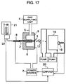
- FIG. 17 there is shown a cross sectional view, partly in block diagram, of a structure of a capillary electrophoresis/mass spectrometer coupling system according to an embodiment of the present invention.
- a mixed solution is introduced into a capillary electrophoresis system 21, and is electrophoresed by a high voltage applied across both ends of a fused-silica capillary 2 so as to be separated.
- the separated solution is then introduced into the capillary 2 through a metallic conduit 8 having an electric potential set to the ground level after having been detected in a detection unit 22.
- a tip of the capillary 2 is substantially coaxially inserted into an orifice 3.
- Nitrogen gases which have been supplied from a gas supplying unit 4 are introduced into an ion source body 6 through a gas introducing conduit 5 so as to be discharged through the orifice 3 to the outside in the form of a gas flow.
- An orifice plate 9 is made of metal, and a suitable voltage is applied to the metallic orifice plate 9 by a power source 7.
- the liquid which has reached the tip of the capillary 2 is sprayed to the outside at an atmospheric pressure by assistance of the gas flow.
- Both the ions and the charged droplets which have been produced in the sprayed gases are introduced into a vacuum through an orifice 17 in an inlet port of a mass spectrometry unit 18, and then are subjected to the mass separation by application of an electric field or a magnetic field in the mass spectrometry unit 18 installed in a high vacuum unit.
- the ions which have been subjected to the mass separation are detected by an ion detecting unit 19.
- An output signal outputted from the ion detecting unit 19 is sent to a computer 20.
- an instruction to control the operation of both the power source 7 and the mass spectrometry unit 18 is issued from the computer 20.
- an output signal outputted from the ion detecting unit 19 is sent to the computer 20 in order to be analyzed.
- the capillary electrophoresis system 21 there are contained materials which become the positive ions by the spray and materials which become the negative ions by the spray. For this reason, for example, even when the materials to become the negative ions are separated, if only the positive ions can not be produced by the spray or only the positive ions can not be analyzed, such materials can not be analyzed. Then, while the separated materials are sprayed through the capillary 2, the polarity of the voltage applied to the orifice plate 9 is reversed so as to analyze both the positive ions and the negative ions. Since the electric potential of the metallic conduit 8 is set to the ground level, analysis of the positive/negative ions does not influence upon the capillary electrophoresis system 21 at all. Even if the solution separating means such as a liquid chromatograph is used instead of the capillary electrophoresis system 21, the high sensitivity separation analysis of the mixed solution is realized online in a completely similar manner.
- the solution separating means such as a liquid chromatograph
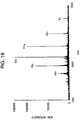
- Fig. 18 there is shown a mass spectrum which is obtained from the experimental results in which when setting an applied voltage to -1 kV, ions which are produced from a cytochrome-C solution with 10 ⁇ mol/l containing strong acid added thereto are subjected to the mass spectrometry.
- a solvent is 50% methyl alcohol liquid containing 0.1% TFA (trifluoroacetic acid) added thereto.
- This solution is introduced into the capillary at a flow rate of 30 ⁇ l/min, and the ions which have been produced by the spray using the gas flow of the sonic velocity are analyzed by a quadruple ion trap mass spectrometer. From Fig.
- Fig. 19 there is shown a mass spectrum which is obtained from the experimental results in which the ions which are produced from a cytochrome-C solution with 10 ⁇ mol/l concentration containing weak acid added thereto are subjected to the mass spectrometry.
- a solvent is 48% methyl alcohol liquid containing 5% acetic acid added thereto.
- the measurement conditions are the same as those in Fig. 18.
- the ion intensity obtained from the solution containing strong acid added thereto is about 1/3 of that obtained from the solution containing weak acid added thereto, but the S/N ratio of the former is approximately equal to that of the latter. Therefore, even when a strong acid solution is added to the sample, there arises no problem in the present ionization method.
- the higher stability and reproducibility of the ion production can be obtained as compared with both the electrospray ionization method and the ion spray ionization method which utilize the electrostatic spray phenomenon. Since even if the spray is restarted after having been temporarily stopped, the ion production is reproduced, the operationalization of the ion source is very high because only the gas spray of the solution is utilized in the ion production. In addition, since the electrostatic spray is not utilized in the ion production at all, the materials contained in the strong acid solution can also be ionized.
Abstract
Description
- The present invention relates in general to a mass spectrometer and a mass spectrometry, and more particularly to a mass spectrometer and a mass spectrometry each of which employs an ion source for ionisation of compounds contained in a solution.
- There is description of a sonic spray inonization method in an article of "Sonic Spray Ionization Method for Atmospheric Pressure Ionization Mass Spectrometry", Analytical Chemistry, Vol. 66, No. 24, December 15, 1994, pp. 4557 to 4559. In the sonic spray ionization method, gases are caused to flow coaxially through a capillary from the outside of the capillary so as to spray the liquid through a tip of the capillary, thereby stably producing ions and charged droplets. In the case where the flow rate of gas at the tip of the capillary is substantially equal to the sonic velocity, an amount of positive and negative ions produced by the spray becomes maximum. In this case, neither an electric field nor discharge is applied to the liquid. The sprayed fine droplets thus produced are neutral in the polarity as a whole and hence an amount of positive ions is substantially equal to an amount of negative ions.
- In addition, there is description of an electrospray ionization method in an article of "Electrospray Ion Source. Another Variation on the Free-Jet Theme", The Journal of Physical Chemistry, Vol. 88, No. 20, 1984, pp.4451 to 4459, or U. S. Patent No. 5,130,538. In the electrospray ionization method, a high voltage of 2.5kV or more is applied to a metallic capillary into which the liquid is introduced and a counter electrode (corresponding in position to an inlet port for ions of a mass spectrometer). That is, the high voltage is applied to the liquid. As a result, the liquid is sprayed in the form of charged droplets through a tip of the capillary into a space in which an electric field is applied between the capillary and an counter electrode (the electrostatic spray phenomenon), thereby producing ions charged positive/negative from the charged droplets. In this connection, the polarity of the charged droplets and the ions matches the polarity of the applied voltage. In the electrospray ionization method, multiply charged ions can be produced, and hence the electrospray ionization method is utilized for analysis of protein or the like in many cases. The flow rate of liquid is normally used in the range of 0.001 to 0.01 ml/min.
- In addition, there is description of an ion spray ionization method in an article of "Ion Spray Interface for Combined Liquid Chromatography/Atmospheric Pressure Ionization Mass Spectrometry", Analytical Chemistry, Vol. 59, No. 22, November 15, 1987, pp. 2642 to 2646, or U. S. Patent No. 4,861,988. In the ion spray ionization method, similarly to the electrospray ionization method, a high voltage of 2.5kV or more is applied between the liquid at a tip of a spraying capillary and a counter electrode (corresponding in position to an inlet port for ions of a mass spectrometry unit). As a result, the liquid is sprayed in the form of ions and charged droplets through the tip of the capillary into a space in which an electric field is applied between the capillary and the counter electrode (the electrostatic spray phenomenon). In the ion spray ionization method, unlike the electrospray ionization method, gases are caused to flow into the outside of the spraying capillary in order to promote vaporization of the charged droplets. As a result, since the ions are produced utilizing the same electrostatic spray phenomenon, the ion thus produced are the same as those in the case of the electrospray ionization method at all. Thus, the polarity of the charged droplets and the ions matches that of the applied voltage. However, the flow rate of liquid is used in the range of 0.01 to 1 ml/min and it is larger than that in the electrospray ionization method. In addition, the flow rate of gas must not exceed 216 m/sec.
- Further, there is description of an ionization method, in which when spraying liquid in the form of gases, a high voltage of 3.5kV is applied to an electrode which is provided in the vicinity of a spraying portion, thereby producing charged droplets and ions, in an article of "Field induced ion evaporation from liquid surfaces at atmospheric pressure", J. Chem. Phys., Vol. 71, No. 11, December 1979, pp.4451 to 4463, or U. S. Patent No. 4,300,044. In this example, liquid and gases are respectively sprayed through an injection needle with 0.3mm inner diameter. Unlike the sonic spray ionization method and the ion spray ionization method, however, the structure is adopted such that the direction of spraying the liquid is substantially perpendicular to the direction of the gas flow. The flow rate of the gas flow is not clear.
- Now, when a mixture in solution is directly introduced to the mass spectrometer, it may be impossible in some cases to identify the mixture, since the resultant mass spectra are too complicated. For this reason, in the analysis of a mixture, a method is adopted in which the separation of the mixture in solution is firstly carried out using means such as a liquid chromatograph or a capillary electrophoresis system and the resultant extract is introduced into the mass spectrometer. That is, a liquid chromatograph/mass spectrometer and a capillary electrophoresis/mass spectrometer are present in each of which the separation and analysis of the mixture are realized online. In the liquid chromatograph, a solution is caused to flow through a column, which is packed with a material, by a pump at a fixed flow rate, thereby carrying out the separation of the mixture in solution. Therefore, an electric potential of the extract is the ground level. On the other hand, in the capillary electrophoresis system, a high voltage in the range of 20 to 30kV or so is applied between the both ends of the capillary into which the solution is introduced, and then the mixture is separated on the basis of the electrophoresis. Normally, an electric potential at the outlet port side of the capillary is set to the ground level, and hence an electric potential of the extract is set to the ground level.
- In the mass spectrometer, the analysis of the ion of interest is carried out on the basis of a value of m/z which is obtained by dividing the mass m of the ion by the charge number thereof z. The mass spectrometer in which the upper limit of the mass range of the mass spectrometry is very high is not suitable for practical use because of its large scale and its high cost. Therefore, in the general mass spectrometer, the upper limit of the mass range of the mass spectrometry is in the range of 1,000 to 2,000 or so in the value of m/z.
- Now, in the above-mentioned prior art, the ions are mainly produced from the fine charged droplets. In the above-mentioned prior art relating to the electrospray ionization method and the ion spray ionization method, the charged droplets each having high density of electric charge are produced, and hence in the multiply-charged ions each having the charge state number z of 3 or more can be produced. Therefore, even in the case of the material, such as protein, having the giant mass m of several tens of thousands or so, the analysis thereof can be carried out since the value m/z is within the range of the mass spectrometry. However, the above-mentioned prior art relating to the sonic spray ionization method and the above-mentioned fourth prior art show a tendency in which the charged droplets each having low density of electric charge are produced and hence the ions each having the small charge state number are produced. That is, the production and the mass spectrometry of a singly-charged ion and a doubly-charged ion such as peptide can be made possible. However, in the analysis of the sample, such as protein, having the very large mass number m, since the multiply-charged ions each having the charge state number z of 3 or more can not be produced, the value of m/z departs from the mass range of the mass spectrometry and hence the mass analysis can not be carried out at all. This is a disadvantage.
- In addition, in the above-mentioned prior art relating to the electrospray ionization method and the ion spray ionization method, the high voltage is applied to the liquid, and the ions and the charged droplets are produced on the basis of the electrostatic spray phenomenon. The large charged droplets each of which has low density of electric charge and the size of which is on the micron order as well as the fine charged droplets each having high density of electric charge are contained in the droplets which are produced on the basis of the above-mentioned phenomenon. The mass of the highly charged droplet is too large as compared with an amount of electric charges thereof, and hence it is difficult to control its movement by application of an electric field or a magnetic field. For this reason, when the mass spectrometry is carried out using a quadruple mass spectrometer or a quadruple ion trap mass spectrometer, the large charged droplets reach a detector without mass separation, and hence such droplets are detected in the form of random noises. In particular, the above-mentioned prior art relating to the ion spray ionization method shows a remarkable tendency that the highly charged droplets are readily produced since the flow rate of the liquid is high. The same problem is also applied to the above-mentioned fourth prior art. In the above-mentioned fourth prior art, the liquid is sprayed by assistance of the gas flow. However, the spraying portion adopts the structure such that the direction of spraying the liquid is substantially perpendicular to the direction of the gas flow. For this reason, a difference of the flow rate of the gas occurs between the upstream side of the gas flow and the downstream side of the gas flow at a tip of the injection needle through which the liquid is sprayed, and as a result, there arises a problem in dispersion in the droplet size that the size of the droplet becomes larger as the droplet is produced in the more downstream side. In addition, an electrode (an electrode 27 in Fig. 2 of U. S. Patent No. 4,300,044) is constructed by one bar. For this reason, the density of electric charge of the droplet which is produced in a region, in the portion for spraying the liquid, in the vicinity of the electrode is different from the density of electric charge of the droplet which is produced in a region away therefrom. As a result, the large droplet having low density of electric charge is largely produced. In the above-mentioned fourth prior art, though the counter gas flow is generated at the inlet port for ions of the mass spectrometer in order to promote vaporization of the droplets, it is impossible to achieve the sufficient vaporization of the droplets. As described above, the ions are mainly produced from the fine charged droplet. In this connection, it is well known that the efficiency of producing ions is high as the size of the droplet is smaller. Then, the efficiency of producing ions from the large charged droplet is so low as to be able to be disregarded. As a result, there arises a problem that due to production of the large charged droplets, the sensitivity of detecting an ion is remarkably reduced by reduction of the intensity of a signal and increase of the noise level.
- In addition, in the above-mentioned prior art relating to the electrospray ionization method and the ion spray ionization method, there is a problem, inherent in the electrostatic spray phenomenon, that it is necessary to adjust the position of the ion source whenever starting the spray in order to optimize the intensity of ions, and hence the operation for the system is complicated. This problem results from the fact that the electrostatic spray phenomenon shows the property that the shapes of the jet produced by spraying the solution vary remarkably due to contamination and wetting of the spraying capillary and the counter electrode (corresponding in position to the inlet port for ions of the mass spectrometry unit). Therefore, in the above-mentioned prior art relating to the electrospray ionization method and the ion spray ionization method, there arises a problem that the operation for the system requires a great deel of skill and hence the operating efficiency is extremely low.
- In addition, in the above-mentioned prior art relating to the electrospray ionization method and the ion spray ionization method, in the case where the liquid chromatograph/mass spectrometer system or the capillary electrophoresis/mass spectrometer system is adopted in which the mixture separating means such as a liquid chromatograph or a capillary electrophoresis system is coupled to the upstream side thereof, since the high voltage is applied to the whole mixture separating means, there is a risk that during handling of the mixture separating means, an operator may get an electric shock in some cases. The electric potential of the whole mixture separating means may be set to the ground level when using the system in some cases. In such cases, the reproducibility of ion production and ion analysis is remarkably reduced since a sort of electrophoresis is realized in the capillary. For this reason, the liquid chromatograph/mass spectrometer system and the capillary electrophoresis/mass spectrometer system do not fulfill their functions in terms of operation as well as function. This is a problem.
- In addition, each of the electrospray ionization method and the ion spray ionization method is a method wherein the voltage is directly applied to the sample solution, and by an electrostatic force occurring between the solution and the electrode of the mass spectrometer, the solution is splayed so as to be ionized. Therefore, there arises a problem that when adding strong acid to the sample solution, since a current is caused to flow through the sample solution, no electrostatic spray phenomenon occurs and hence the ionization of the sample solution is difficult.
- In view of the foregoing problems associated with the prior art, it is therefore an object of the present invention to provide a high sensitivity mass spectrometer and a high sensitivity mass spectrometry employing a high efficiency ion source by which production and analysis of multiply-charged ions each having the charge state number of 3 or more can be realized in order to analyze a sample having the large mass number.
- It is another object of the present invention to provide a high sensitivity mass spectrometer and a high sensitivity mass spectrometry by which a large charged droplet resulting in reduction of the sensitivity of detecting ions is not produced too much.
- It is still another object of the present invention to provide a high sensitivity mass spectrometer and a high sensitivity mass spectrometry employing a high efficiency ion source which is excellent in operationalization.
- It is yet another object of the present invention to provide a high sensitivity mass spectrometer and a high sensitivity mass spectrometry employing a high efficiency ion source each of which is capable of setting an electric potential of liquid to the ground level, and is safe in operation and is capable of providing high reproducibility for the production and analysis of ions.
- It is a further object of the present invention to provide a mass spectrometer and a mass spectrometry employing an ion source in which even when subjecting a sample solution containing strong acid added thereto to mass spectrometry, a voltage is not directly applied to the sample solution so as for a current not to be caused to flow through the sample solution, and the electrostatic spray phenomenon is not utilized at all.
- According to a first aspect of the present invention, there is provided a mass spectrometer employing an ion source including: a passage through which liquid is caused to flow to a predetermined position, at least a part of the passage being made of an insulating material; electric field applying means for applying a voltage to the liquid through the insulating material so as to generate an electric field applied thereto; and spray means for spraying therethrough the solution so as to produce charged gases, the spray means being arranged downstream with respect to the liquid to which the electric field is applied.
- In addition, according to a second aspect of the present invention, there is provided a mass spectrometer including: separation means for separating sample liquid containing a mixture; a passage through which the sample liquid thus separated is caused to flow to a predetermined position, at least a part of the passage being made of an insulating material; electric field applying means for applying a voltage to the sample liquid through the insulating material so as to generate an electric field applied thereto; spray means as a room having a gas supplying unit for supplying gases, a gas supply port for supplying therethrough the gases from the gas supplying unit, an injection port for discharging therethrough the gases, and a holding portion for holding the passage; and analysis means, such as a quadruple mass spectrometer or a quadruple ion trap mass spectrometer, for subjecting the sprayed gases to mass spectrometry so as to analyze the sprayed gases.
- In addition, according to a third aspect of the present invention, there is provided a mass spectrometer including: separation means for separating sample solution containing a mixture; detection means for detecting the characteristics of the separated sample solution; a passage through which the separated sample solution is caused to flow to a predetermined position, at least a part of the passage being made of an insulating material; electric field applying means for applying a voltage to the sample liquid through the insulating material so as to generate an electric field applied thereto; spray means as a room having a gas supplying unit for supplying gases, a gas supply port for supplying therethrough the gases from the gas supplying unit, an injection port for discharging therethrough the gases, and a holding portion for holding the passage; analysis means for subjecting the sprayed gases to mass spectrometry so as to analyze the sprayed gases; and a control unit for controlling both the electric field applying means and the analysis means on the basis of a signal outputted from the detection means.
- According to a fourth aspect of the present invention, there is provided a mass spectrometer including: an injection port for spraying therethrough liquid so as to produce multiply-charged ions each being at least triply-charged, a part of or the whole injection port being made of an insulating material; a first electrode arranged in the periphery of the injection port; and a second electrode arranged opposite to the first electrode for generating a uniform electric field between the first electrode and the second electrode.
- In addition, according to a fifth aspect of the present invention, there is provided a mass spectrometer having mixture separating means coupled thereto including: the mixture separating means for separating mixture; a metallic portion for determining an electric potential of the sample solution separated by the mixture separating means; a passage to which the liquid is supplied; electric field applying means for applying a voltage to the liquid flowing through the passage so as to generate an electric field applied thereto, the means being electrically insulated from the passage; an injection port for spraying therethrough the liquid by an ion source having spray means for spraying the liquid so as to produce charged droplets, so as to produce multiply-charged ions each being at least triply-charged, the injection port being arranged downstream with respect to the liquid to which the electric field is applied, a part of or the whole injection port being made of an insulating material; a first electrode arranged in the periphery of the injection port; and a second electrode arranged opposite to the first electrode for generating a uniform electric field between the first electrode and the second electrode.
- In addition, according to a sixth aspect of the present invention, there is provided a mass spectrometry, wherein multiply-charged ions each being at least triply-charged are produced in a uniform electric field which is generated between a first electrode arranged in the periphery of an injection port for spraying therethrough liquid and a second electrode arranged opposite to the first electrode, and the resultant multiply-charged ions are analyzed by a mass spectrometry unit.
- In addition, according to a seventh aspect of the present invention, there is provided a mass spectrometry including the steps of: separating liquid; applying an electric field to the liquid which has been separated and is determined with an electric potential thereof; and passing multiply-charged ions each being at least triply-charged through a uniform electric field, which is generated between a first electrode arranged in the periphery of an injection port for spraying therethrough the liquid and a second electrode arranged opposite to the first electrode, so as to supply the multiply-charged ions to a mass spectrometry unit for carrying out mass analysis and also to subject the multiply-charged ions to mass spectrometry to analyze the multiply-charged ions.
- In addition, according to a eighth aspect of the present invention, there is provided a mass spectrometry including the electric field applying step of changing the polarity of an electric field applied to liquid in correspondence to the polarity of multiply-charged ions each being at least triply-charged which are produced in a uniform electric field generated between a first electrode arranged in the periphery of an injection port for spraying therethrough the liquid and a second electrode arranged opposite to the first electrode.
- Further, according to a ninth aspect of the present invention, there is provided a mass spectrometry including: the electric field applying step of changing the polarity of an electric field applied to liquid; and the step of producing multiply-charged ions, each being at least triply-charged and having the polarity varying in correspondence to the polarity of the electric field applied to the liquid, in a uniform electric field which is generated between a first electrode arranged in the periphery of an injection port for spraying therethrough the liquid and a second electrode arranged opposite to the first electrode.
- In the conventional sonic spray ionization method, firstly, droplets each being electrically neutral are produced by spraying the liquid. While the positive ions and the negative ions which are substantially equal in the number to each other are contained in the droplet, the distribution of density of the positive and negative ions in the vicinity of the surface of the droplet is remarkably different from that in the central portion of the droplet due to the surface electric potential which is determined on the basis of combination of the droplet and the circumambient gases. In addition, the fine droplets are separated from the surface of the droplet by the gas flow of the sonic velocity. Since the number of positive ions is different from the number of negative ions in each of those fine droplets, the density of electric charge is low, but the fine droplet is changed positive or negative as a whole. The ions are produced on the basis of the process of evaporating ions from the fine charged droplet or the perfect vaporization of the charged droplet.
- In the ionization method and the ion source of the present invention, the electric field is applied through the electrode arranged in the outside to the liquid which is introduced into the fused-silica capillary in the sonic spray ionization method. For example, when applying the negative voltage to the liquid, the density of the positive ions is much higher than the density of the negative ion in the area in the vicinity of the surface of the liquid. As a result, the droplets which are charged positive when spraying the liquid by assistance of the gas flow are preferentially produced, and hence the sprayed gases are charged positive. In the droplet, the positive ions are concentrated on the area in the vicinity of the surface by the Coulomb repulsion. The density of electric charge of the charged droplet is higher than the density of electric charge of the charged droplet which is produced by the normal sonic spray ionization method. In addition, at the time when the fine droplets are separated from the surface of the droplet by assistance of the gas flow of the sonic velocity, the fine droplets each having the very high density of electric charge are produced. As described above, it is well known that the ions are produced on the basis of the process of evaporating ions from the fine droplet or the perfect vaporization of the charged droplet. In the former, the efficiency of producing multiply-charged ions is in general remarkably so low as to be able to be disregarded as compared with that of producing singly charged ions. However, in the case where the density of electric charge of the droplet is high, since the Coulomb repulsion in the droplet is remarkably large, the efficiency of producing multiply-charged ions becomes high. For this reason, the multiply-charged ions can also be produced. In the ionization method of the present invention, before the liquid has been sprayed, the density of positive or negative ions of the area in the vicinity of the surface of the liquid can be made very high. Therefore, it is meaningless that an electric field is applied to the droplets which have been produced by the spray. It is required that an electric field is applied to the liquid before being sprayed.
- In addition, in the mass spectrometer and the mass spectrometry of the present invention, since the electrostatic spray phenomenon is not utilized for the ion production at all, the ion production is not influenced by the contamination and wetting of the inlet port for ions of the mass spectrometry unit and the spraying capillary at all. Therefore, the system can be readily handled, and the reproducibility of ion production is also high.
- In addition, in the mass spectrometer system and the mass spectrometry of the present invention, the electric potential of the liquid introduced into the ion source can be set to the ground level. For this reason, the capillary electrophoresis system or the liquid chromatograph can be readily coupled to the portion of the system which is located upstream with respect to the ion source. In this connection, the reproducibility of the ion production is not degraded by this coupling at all.
- As for a method of applying an electric field to the liquid from the outside, there is a method wherein a capillary is made of an insulating material such as quartz or resin, and a voltage is applied to a metallic orifice into which a tip of the capillary is inserted. As for another method, there is a method wherein a capillary is made of an insulating material, and an outer surface of a portion near a tip of the capillary is coated with metal, and under this condition, a voltage is applied to the outer surface of the capillary. In addition, there is also still another method wherein an insulating capillary is inserted into a metallic conduit to which a voltage is to be applied. In all methods, maintaining a distance between the surface of the liquid and the electrode constant is required for the ion production of high efficiency. In the case where the capillary is made of a conductive material such as metal, a high voltage needs to be applied to the electrode since the metallic capillary has the electrical shielding effect.
- In the present invention, since the electric field is applied to the solution through the insulating material such as quartz or resin, the voltage is not directly applied to the solution. For this reason, even in the case where strong acid solution is applied to the mass spectrometry, no current is caused to flow through the solution. Further, since the solution is sprayed by assistance of the gas flow, the ion production is not hindered at all.
- The above and other objects as well as advantages of the present invention will become clear by the following description of the preferred embodiment of the present invention with reference to the accompanying drawings, wherein:
- Fig. 1 is a schematic view, partly in cross sectional view, showing a structure of an ion source according to an embodiment of the present invention;
- Fig. 2 is a cross sectional view, partly in block diagram, showing a structure of an ion source according to an embodiment of the present invention;
- Fig. 3 is a perspective view showing a structure of an ion source according to the embodiment of the present invention shown in Fig. 2;
- Fig. 4 is a graphical representation showing the relationship between a voltage applied to an orifice and a total ion current;
- Fig. 5 is a mass spectrum which is obtained from a cytochrome-C solution;
- Fig. 6 is a mass spectrum which is obtained from a cytochrome-C solution by the ion spray ionization method;
- Fig. 7 is a mass spectrum which is obtained from a myoglobin solution;
- Fig. 8 is a mass spectrum which is obtained from a hemoglobin solution;
- Fig. 9 is a graphical representation showing the relationship between a flow rate of sprayed gases and the relative ion density;
- Fig. 10 is a cross sectional view, partly in block diagram, showing a structure of an ion source according to another embodiment of the present invention;
- Fig. 11 is a cross sectional view, partly in block diagram, showing a structure of an ion source according to still another embodiment of the present invention;
- Fig. 12 is a cross sectional view, partly in block diagram, showing a structure of an ion source according to yet another embodiment of the present invention;
- Fig. 13 is a cross sectional view, partly in block diagram, showing a structure of an ion source according to a further another embodiment of the present invention;
- Fig. 14 is a cross sectional view, partly in block diagram, showing a structure of an ion source according to an even further another embodiment of the present invention;
- Fig. 15 is a cross sectional view, partly in block diagram, showing a structure of a mass spectrometer according to an embodiment of the present invention;
- Fig. 16 is a cross sectional view, partly in block diagram, showing a structure of a capillary electrophoresis/mass spectrometer coupling system according to an embodiment of the present invention;
- Fig. 17 is a cross sectional view, partly in block diagram, showing a structure of a capillary electrophoresis/mass spectrometer coupling system according to another embodiment of the present invention;
- Fig. 18 is a mass spectrum which is obtained from a cytochrome-C solution containing strong acid (trifluoroacetic acid) added thereto; and
- Fig. 19 is a mass spectrum which is obtained from a cytochrome-C solution containing weak acid (acetic acid) added thereto.
- The preferred embodiments of the present invention will hereinafter be described in detail with reference to the accompanying drawings.
- Referring first to Fig. 1, there is shown a schematic view, partly in cross sectional view, of a structure of an ion source according to an embodiment of the present invention. Liquid is introduced into a
capillary 2 through apassage 1. A tip of thecapillary 2 is substantially coaxially inserted into anorifice 3. Gases which have been supplied from agas supplying unit 4 are introduced into anion source body 6 through agas introducing conduit 5 and then are discharged through theorifice 3 to the outside. Theorifice 3 is made of metal, and a suitable voltage is applied across theorifice 3 and ametallic conduit 8 by apower source 7. Though no current is caused to flow between theorifice 3 and the liquid since electrical conduction is not established between theorifice 3 and the liquid, a suitable electric field is applied to the liquid. The liquid which has reached at the tip of thecapillary 2 is sprayed by assistance of the gas flow. Ions and fine charged droplets are produced in the sprayed gases. - Referring to Fig. 2, there is shown a cross sectional view, partly in block diagram, of an ion source according to an embodiment of the present invention. After having been introduced into the
metallic conduit 8, an electric potential of which is set to the ground level, at a flow rate of 5 to 100 µl/min, the liquid is introduced into a fused-silica capillary 2 (its inner diameter is 0.1mm and its outer diameter is 0.2mm). Anorifice plate 9 through which an orifice 3 (its inner diameter is 0.4mm and its outer diameter is 1.0mm) is bored is made of duralumin, and a suitable voltage is applied to theorifice plate 9 by thepower source 7. Thecapillary 2 is inserted into twoTeflon conduits 10 and twostainless conduits 11, and is adhered to thestainless conduits 11 by adhesive. In addition, the liquid is electrically insulated from theion source body 6 through a space defined between the twostainless conduits 11. The central axis of thecapillary 2 is substantially aligned with the central axis of theorifice 3, and a tip of thecapillary 2 is exposed from theorifice plate 9 to the outside by about 0.2mm. Thestainless conduits 11 are also used to fix thecapillary 2 to theion source body 6. When theorifice plate 9 is cooled by the adiabatic expansion of the gases, the resultant droplet may coagulate so that it may not become fine in some cases. As a result, since large charged droplets are produced, an amount of ions is reduced. This problem is avoided in such a way that a heater is provided in either theorifice plate 9 or theion source body 6 in order to heat it, or the gases to be introduced into the ion source is previously heated. The gases are introduced into thegas introducing conduit 5 from a gas bomb or a gas compressor. A gas flow rate regulating unit such as a mass flow controller or a purge meter is installed in the middle position between the gas bomb or the gas compressor and thegas introducing conduit 5 in order to regulate the flow rate of gas for use in the spraying operation. When the gas flow rate is just 3 l/min, the flow rate of gas in the vicinity of the tip of thecapillary 2 become the sonic velocity. - It is well known that the ions are produced from the fine charged droplet with 10nm or less diameter. In the present embodiment, similarly to the sonic spray ionization method, the fine charged droplets are produced by assistance of the gas spray. While the size of the average droplet which is produced by assistance of the gas spray is decreased as the gas flow rate is further increased, the size of the average droplet is increased when the gas flow rate becomes the supersonic. This results from that the shock wave is generated (refer to Fig. 9). Therefore, the size of the average droplet becomes minimum when the gas flow rate is the sonic velocity, and hence the ion production is most efficiently carried out. The efficiency of producing fine droplets is high, and as a result, the efficiency of producing ions is high as a wall thickness of the
capillary 2 is smaller. - For production of the gas flow of the sonic velocity, if an ambient pressure of the ion source is 1 atmosphere and also a thickness of the
orifice 3 can be disregarded, the portion located upstream with respect to theorifice 3 requires a gas pressure of about 2 atmospheres. However, there may be a case where the pressure reduction within theorifice 3 can not be disregarded in correspondence to the thickness of theorifice plate 9. If a suitable pressure gage is provided in theion source body 6 so as to regulate the gas pressure to produce the gas flow of the sonic velocity, this is so convenient. In this case, it is likely to be more acceptable that the pressure is regulated so as to apply a gas pressure in the range of 0.5 to 5 atmospheres or so to the portion located upstream with respect to theorifice 3. In addition, it is also suitable for practical use that the gas flow of the sonic velocity is generated by gas flow rate regulating means such as a purge meter or a mass flow meter. If the thickness of theorifice 3 is too large, the pressure reduction within theorifice 3 is increased and as a result the pressure within theorifice 3 needs to be unnecessarily increased. There is no need of making the thickness of theorifice 3 larger than a wall thickness of theion source body 6. Conversely, if the thickness of theorifice 3 is too small, theorifice 3 can not withstand a pressure difference between the inside and the outside of theion source body 6 in terms of strength. For this reason, it is suitable for practical use that the thickness of theorifice 3 is set to the range of 0.5 to 1mm which is larger than the diameter of thecapillary 2. A portion of theion source body 6 located upstream with respect to theorifice 3 requires a space acting as a gas reservoir so as not to decrease the gas pressure therein. This space requires the size which is 5 or more times as large as that of the diameter of thecapillary 2. - Referring to Fig. 3, there is shown a sketch drawing of the ion source according to the embodiment of the present invention shown in Fig. 2. The sprayed gases are discharged to this side in the figure. While a cross section of the
ion source body 6 when viewed perpendicularly to the central axis of thecapillary 2 is a quadrangle, it may also be made a round shape. Theorifice plate 9 has four holes bored therethrough in addition to theorifice 3, and theorifice plate 9 is screwed on theion source body 6 by using four screws corresponding to the four holes. The positional adjustment is carried out under the microscope such that the center of theorifice 3 is substantially aligned with the center of thecapillary 2, and under this condition, theorifice plate 9 is mounted to theion source body 6 by the four screws. In such a way, a uniform gas flow is generated at the tip of thecapillary 2. From the size in the figure, it is shown that the ion source of the present invention is very compact. - Referring to Fig. 4, there is shown the dependency of the total ion current produced by the spray on a voltage applied to the
orifice 3. This is obtained from the experimental results in the case where a solution of 47.5% methyl alcohol/47.5% water/5%acetic acid is used as the sample liquid. From the experimental results, it is shown that when applying a positive voltage to the sample solution, the negative ions and charged droplets are produced, while when applying a negative voltage thereto, the positive ions and charged droplets are produced. That is, it is shown that if applying a voltage of the polarity opposite to the polarity of the ions which are intended to be produced, the ions of the desired polarity are produced. In addition, it is shown that while the total ion current is decreased along with increase of the applied voltage when the absolute value of the applied voltage is equal to or smaller than 1kV, the total ion current is not changed too much to be saturated when the absolute value of the applied voltage is equal to or larger than 1kV. This phenomenon shows that the density of ions of the same polarity in the vicinity of the surface of the liquid just before being sprayed reaches the limit. Therefore, it is suitable for practical use that the absolute value of the applied voltage is set to the range of 1 to 2kV on the basis of the experimental results. - Now, assuming that the electric conductivity of the liquid is sufficiently high, an electric potential at a portion in the vicinity of the central axis of the
capillary 2 can be regarded as 0V, and also the intensity of an electric field can be estimated as 5,000kV/m (= 1,000V/0.2mm). Therefore, either in the case where an inner diameter of theorifice 3 is larger, or in the case where an electrode is provided in the position more apart therefrom, the higher voltage needs to be applied. - Referring to Fig. 5, there is shown a mass spectrum which is obtained from the experimental results in which ions produced when setting the applied voltage to -1kV is subjected to the mass spectrometry. That is, this is obtained from the experimental results in which a solution of cytochrome-C with 1 µmol/l concentration (a kind of protein, and its molecular weight is about 12,500)(a solvent is 48% methyl alcohol liquid containing 5% acetic acid added thereto) is introduced into the
capillary 2 at a flow rate of 30 µl/min, and the ions which have been obtained by spraying the solution by assistance of the gas flow of the sonic velocity are analyzed using a quadruple mass spectrometer. From the mass spectrum, it is shown that a series of multiple-charged ions ranging from a 13+ ion to a 20+ ion are clearly detected in an area of m/z equal to or lower than m/z = 1,000 with a 16+ ion (m/z = 766), in which sixteen protons are added to a cytochrome-C molecule, as center. - Heretofore, the ion spray ionization method and the electrospray ionization method (the principle of producing ions is substantially the same with the two methods) have been utilized for production of multiply-charged ions. Then, the ions are produced from the same cytochrome-C solution as the above-mentioned solution by utilizing the ion spray ionization method, and the resultant ions are detected by the same quadruple mass spectrometer. These experimental result are shown in the form of a mass spectrum in Fig. 6. The axis of ordinate is the same as that in Fig. 5. From Fig. 6, it is shown that with respect to the multiply-charged ions, the same spectrum pattern of the mass spectrum as that in Fig. 5 is obtained, but the ion intensity is about 2.6 times as low as that of the experimental results shown in Fig. 5. This corresponds to the ion detection sensitivity which is obtained when the applied voltage is set to about 700V in the ion source of the present invention. In addition, from Fig. 6, it is shown that the noise level is much higher than that shown in Fig. 5. Those noises result from that the larger charged droplets are produced in large quantities by the ion spray ionization method as compared with the ionization method of the present invention, and those larger charged droplets are detected in the form of random noises. In Fig. 6, the S/N ratio is about 9 times as small as that of Fig. 5. As a result, it is shown that when utilizing the ionization method of the present invention shown in Fig. 5, the ion detection of higher sensitivity can be carried out. In addition, in Fig. 6, many ions resulting from the solvent are detected in the area of m/z equal to or lower than m/z = 300. The analysis of such a complicated mass spectrum requires experience.
- Referring to Fig. 7, there is shown a mass spectrum which is obtained from a myoglobin solution (the concentration is 1 µmol/l, and a solvent is 48% methyl alcohol containing 5% acetic acid added thereto). Referring to Fig. 8, there is shown a mass spectrum which is obtained from a hemoglobin solution (the concentration is 1 µmol/l, and a solvent is 48% methyl alcohol containing 5% acetic acid added thereto). Myoglobin has the molecular weight of 17,200, and from the myoglobin solution, a series of multiply-charged ions ranging from a 18+ ion to a 26+ ion are detected, with a 22+ ion (m/z = 772), which has twenty-two protons added thereto, as center. Hemoglobin is a kind of protein with 64,500 molecular weight in which two kinds of sub-units are contained, and for every kind of sub-unit, the two associated sub-units are coupled to each other. In Fig. 8, the mass spectrum of the sub-units is observed.
- Referring to Fig. 9, there is shown the dependency of the flow rate F of the sprayed gases on the relative intensity of the 16+ ion in Fig. 5. There is used herein the ion source of the embodiment shown in Fig. 2. From the graphical representation, the relationship is obtained in which the flow rate of gas is increased along with increase of the flow rate of gas. In the present experiments, it is previously known that the flow rate of gas corresponds to the sonic velocity (Mach 1) when the flow rate of gas is about 3 l/min, and the flow rate of gas is equal to or lower than
Mach 2 when the flow rate of gas is about 7 l/min (refer to the above-mentioned first article of Analytical Chemistry, Vol. 66, No. 24, December 15, 1994, pp.4457 to 4559). From the figure, it is shown that while no ion is produced when the flow rate of gas is equal to or lower than 1.4 l/min, and the relative ion intensity is increased along with increase of the flow rate of gas, the relative ion density becomes maximum when the flow rate of gas is about 3 l/min, and the relative ion intensity is decreased due to generation of the shock wave when the flow rate of gas is equal to or higher than about 3 l/min (the supersonic area). Thus, while the dependency of the relative ion intensity on the gas flow rate of the present invention is similar to that utilizing the conventional sonic spray ionization method, it is the feature inherent in the present invention that the sprayed gases which are produced from the ion source of the present invention are charged positive or negative as a whole. - Now, as described above, the flow rate of gas may be controlled by regulating the gas flow rate F using the flow rate regulating means. In the example of the ion source shown in Fig. 2, an area S of a cross section of a clearance gap defined between the orifice and the capillary when viewed perpendicularly to the capillary is calculated to be 9.4 × 10⁻⁸ m2 . If the flow rate of gas is under the standard state (20°C, 1 atmosphere), a ratio of F/S is estimated to be 250 m/sec when F is 1.4 l/min, and it is estimated to be 1,200 m/sec when F is 7 l/min. In this connection, take notice of that the unit of the ratio F/S is velocity, but the ratio F/S is different from the flow rate of gas.
- The flow rate of gas may be controlled by the gas presser within the ion source. In Fig. 9, the production of the ions is started at a pressure of about 1.2 atmospheres. Assuming that the isoentropic flow is established, in the case where the thickness of the orifice is sufficiently small. Mach about 0.5 is achieved when the gas pressure is 1.2 atmospheres, and
Mach 1 is achieved when the gas pressure is 2 atmospheres. The gas pressure of 7.2 atmospheres is required for achievingMach 2. By the way, the gas pressure of 40 atmospheres is required for achievingMach 3, and hence in this case, there is a problem in terms of practical use. In order to control the flow rate of gas by the gas pressure, it is suitable for practical use that the gas pressure is regulated in the range of 0.5 to 5 atmospheres. - In this ion source, a diameter of the orifice is 0.4mm, and an outer diameter of the fused-silica capillary is 0.2mm. Therefore, the area S of the cross section of the clearance gap defined between the orifice and the capillary is calculated to be 9.4 × 10⁻⁸ m2. Then, when employing the parameter F/S, the parameter F/S is 250m/sec when the flow rate F of gas is 1.4 l/min, and F/S is 530m/sec when F is the sonic velocity (notice needs to be taken of that while the unit of the parameter F/S is velocity, but it has no relation to the actual flow rate of gas). Even if the flow rate F of gas is increased up to 7 (F/S = 1,200m/sec) or more, the consumption of gas is increased only, and the efficiency of producing ions is not increased. For this reason, actually, the parameter F/S is used in the range of 250 to 1,200m/sec. Since the area S is determined by the structure of the ion source, it is convenient that the flow rate F of gas is regulated using a flow controller such as a mass flow meter or a purge meter.
- The gas flow is used to assist the spray of the liquid. Therefore, the kind of gas does not hardly participate in the ion production. Actually, it is convenient to use nitrogen gases as the gases used to produce the gas flow because nitrogen gases are inexpensive, and also are effective to vaporize the droplets since nitrogen gases are dry. In addition to nitrogen gases, even when using air, oxygen gases, carbon dioxide gases, rare gases, or the like, the same effect can be obtained.
- Referring to Fig. 10, there is shown a cross sectional view, partly in block diagram, of an ion source according to another embodiment of the present invention. Aluminium is deposited onto an outer surface of a tip with 5mm length of a fused-silica capillary (its inner diameter is 0.01mm, and its outer diameter is 0.05mm), and a suitable voltage is applied to the tip of the
capillary 2 by apower source 7. As stated in the description with respect to Fig. 4, in order to produce ions efficiently, it is necessary to generate an electric field having the intensity which is equal to or higher than a certain level. In the present embodiment, a voltage applied to an electrode can be set to a lower level than that in the above-mentioned embodiment shown in Fig. 2. In the present embodiment, since an electric potential of anion source body 6 can be set to the ground level, the safety during operation of the system is very high. - Referring to Fig. 11, there is shown a cross sectional view, partly in block diagram, of an ion source according to still another embodiment of the present invention. A
capillary 2 made of resin is inserted through atubular electrode 12, and a suitable voltage is applied to theelectrode 12 by apower source 7. Thecapillary 2 made of resin is adhered to thetubular electrode 12 by insulating adhesive. If a sufficiently high voltage is applied to thetubular electrode 12, thetubular electrode 12 is not necessarily aligned coaxially with thecapillary 2. However, in the case where thetubular electrode 12 is aligned substantially coaxially with thecapillary 2, the ion production is carried out with a lower applied voltage. In addition, similarly, if the sufficiently high voltage is applied to thetubular electrode 12, theelectrode 12 does not need to have necessarily the tubular shape. The applied voltage has only to be much lower in the case where theelectrode 12 is arranged to this side with respect to the tip of thecapillary 2 as compared with the case where theelectrode 2 is not arranged to this side with respect to the tip of thecapillary 2. - Referring to Fig. 12, there is shown a cross sectional view of an ion source according to yet another embodiment of the present invention. A fused-
silica capillary 2 is heated by aheating block 14 which is heated in turn by aheater 13. Therefore, the liquid which has been introduced into thecapillary 2 is splayed by assistance of heating. The droplets which have been produced in thecapillary 2 by the spray are charged positive or negative by application of an electric field generated through anelectrode 12, thereby producing the charged droplets and the ions. For heating of the liquid, an infrared laser or a lamp may be employed. - Referring to Fig. 13, there is shown a cross sectional view of an ion source according to a further embodiment of the present invention. The liquid which has been introduced into a fused-
silica capillary 2 is sprayed in a transverse direction at a tip of thecapillary 2 by assistance of the gas flow which is produced by agas injection unit 15. In this case, while the relatively larger charged droplets are produced, the positional adjustment of thecapillary 2 can be carried out in a very simple manner. In particular, in the case where there is no need of producing ions, and only the production of the droplets is enough, the present embodiment provides a very simple system for producing charged droplets. - Referring to Fig. 14, there is shown a cross sectional view of an ion source according to an even further embodiment of the present invention. The liquid which has been introduced into a fused-
silica capillary 2 is converted into droplets by aultrasonic vibrator 16. These droplets are charged positive or negative when producing the droplets by application of an electric field generated through anelectrode 12. The sprayed gases charged positive or negative are spatially widely diffused. Each of the above-mentioned embodiments shown in Figs. 12 to 14, respectively, has an advantage that the ions can be produced without using either a gas bomb or a compressor. - Referring to Fig. 15, there is shown a cross sectional view, partly in block diagram, of a structure of a mass spectrometer according to an embodiment of the present invention. The liquid is introduced into a
capillary 2 at a fixed flow rate through apassage 1. A tip of thecapillary 2 is substantially coaxially inserted into anorifice 3. Nitrogen gases which have been supplied from agas supplying unit 4 are introduced into anion source body 6 through agas introducing conduit 5 so as to be discharged through theorifice 3 to the outside. A suitable voltage is applied to ametallic orifice plate 9 by apower source 7. As a result, an electric field is applied to the liquid which has reached the tip of thecapillary 2. The liquid to which the electric field is applied is sprayed to the outside at an atmospheric pressure by assistance of the gas flow generated through theorifice 3. In general, a uniform electric field is present between themetallic orifice plate 9 through which the sprayed gases are produced and anorifice 17 in an inlet port of amass spectrometry unit 18. Both the ions and the charged droplets which have been produced in the sprayed gases are introduced into a vacuum through theorifice 17 in the inlet port of themass spectrometry unit 18, and then are subjected to the mass separation by application of an electric field or a magnetic field in themass spectrometry unit 18 installed in a high vacuum unit. The ions which have been subjected to the mass separation are detected by anion detecting unit 19. An output signal outputted fromion detecting unit 19 is sent to acomputer 20 in order to be analyzed. Both thepower source 7 and themass spectrometry unit 18 can be controlled by thecomputer 20. That is, the positive/negative ions which have been produced on the basis of an intermittent voltage signal generated by thepower source 7 can be subjected to the mass separation synchronously with the ion production so as to be detected. For example, when an electric potential of ametallic conduit 8 is set to the ground level and a rectangular voltage signal with 1kV amplitude is applied to theorifice plate 9 by thepower source 7 so as to produce the positive/negative ions, the positive/negative ions can be analyzed synchronously with the ion production. In the case where the electric potentials of thecapillary 2 or themetallic conduit 8 and theorifice 17 are set to the same electric potential so that no uniform electric field is present in a space when the sprayed gases are produced as well as in the case where an electric potential difference of about 200 V is generated therebetween, there is no problem for ion detection at all. - When setting an electric potential of the
metallic conduit 8 to the ground level, an electric potential of the liquid which is caused to flow through thecapillary 2 can be set to the ground level. Therefore, solution separating means such as a capillary electrophoresis system or a liquid chromatograph can be readily coupled to thepassage 1. - Referring to Fig. 16, there is shown a cross sectional view, partly in block diagram, of a structure of a capillary electrophoresis system/mass spectrometer coupling system of an embodiment of the present invention. A mixed solution is introduced into a
capillary electrophoresis system 21, and then is electrophoresed by a high voltage applied across mutually-opposite ends of acapillary 2 so as to be separated. The separated solution is introduced into thecapillary 2 after having been detected in adetection unit 22. A tip of thecapillary 2 is substantially coaxially inserted into anorifice 2. Nitrogen gases which have been supplied from agas supplying unit 4 are introduced into anion source body 6 through agas introducing conduit 5 so as to be discharged through theorifice 3 to the outside in the form of a gas flow. Anorifice plate 9 is made of metal, and a suitable voltage is applied to themetallic orifice plate 9 by apower source 7. The liquid which has reached a tip of thecapillary 2 is sprayed to the outside at an atmospheric pressure by assistance of the gas flow. Both the ions and the charged droplets which have been produced in the sprayed gases are introduced into a vacuum through anorifice 17 in an inlet port of a mass spectrometry unit, and then are subjected to the mass separation by application of an electric field or a magnetic field in amass spectrometry unit 18 installed in a high vacuum unit. The ions which have been subjected to the mass separation are detected by anion detecting unit 19. An output signal outputted from theion detecting unit 19 is sent to acomputer 20 in order to be analyzed. Both thepower source 7 and themass spectrometry unit 18 can be controlled by thecomputer 20. That is, the positive/negative ions which have been produced on the basis of an intermittent voltage generated by thepower source 7 can be subjected to the mass separation synchronously with the ion production so as to be detected in theion detection unit 19. For example, when an electric potential of ametallic conduit 8 is set to the ground level, and also a rectangular voltage signal with 1kV amplitude is applied to theorifice plate 9 by thepower source 7 so as to produce the positive/negative ions, the positive/negative ions can be analyzed synchronously with the ion production. In the case where the electric potentials of thecapillary 2 or themetallic conduit 8 and theorifice 17 are set to the same electric potential so that no electric field is present in a space where the sprayed gases are produced as well as in the case where an electric potential difference of about 200 V is generated therebetween, there is no problem for ion detection at all. For themass spectrometry unit 18, all kinds of mass spectrometry units such as a quadruple mass spectrometer, a quadruple ion trap mass spectrometer, a magnetic sector type mass spectrometer, a time-of-flight mass spectrometer, and a Fourier transform mass spectrometer may be employed. The electric potential of themetallic conduit 8 is set to the ground level, whereby the electric potential of the mixed solution in thecapillary electrophoresis system 21 can also be set to the ground level. Therefore, thecapillary electrophoresis system 21 can be operated without any difficulty in the separation of the mixed solution, and hence the high sensitivity separation analysis of the mixed solution is realized online. Even if the solution separating means such as a liquid chromatograph is used instead of thecapillary electrophoresis system 21, the high sensitivity separation analysis of the mixed solution is realized online in a completely similar manner. - Referring to Fig. 17, there is shown a cross sectional view, partly in block diagram, of a structure of a capillary electrophoresis/mass spectrometer coupling system according to an embodiment of the present invention. A mixed solution is introduced into a
capillary electrophoresis system 21, and is electrophoresed by a high voltage applied across both ends of a fused-silica capillary 2 so as to be separated. The separated solution is then introduced into thecapillary 2 through ametallic conduit 8 having an electric potential set to the ground level after having been detected in adetection unit 22. A tip of thecapillary 2 is substantially coaxially inserted into anorifice 3. Nitrogen gases which have been supplied from agas supplying unit 4 are introduced into anion source body 6 through agas introducing conduit 5 so as to be discharged through theorifice 3 to the outside in the form of a gas flow. Anorifice plate 9 is made of metal, and a suitable voltage is applied to themetallic orifice plate 9 by apower source 7. The liquid which has reached the tip of thecapillary 2 is sprayed to the outside at an atmospheric pressure by assistance of the gas flow. Both the ions and the charged droplets which have been produced in the sprayed gases are introduced into a vacuum through anorifice 17 in an inlet port of amass spectrometry unit 18, and then are subjected to the mass separation by application of an electric field or a magnetic field in themass spectrometry unit 18 installed in a high vacuum unit. The ions which have been subjected to the mass separation are detected by anion detecting unit 19. An output signal outputted from theion detecting unit 19 is sent to acomputer 20. In response thereto, an instruction to control the operation of both thepower source 7 and themass spectrometry unit 18 is issued from thecomputer 20. Then, an output signal outputted from theion detecting unit 19 is sent to thecomputer 20 in order to be analyzed. - In the materials which are separated by the
capillary electrophoresis system 21, there are contained materials which become the positive ions by the spray and materials which become the negative ions by the spray. For this reason, for example, even when the materials to become the negative ions are separated, if only the positive ions can not be produced by the spray or only the positive ions can not be analyzed, such materials can not be analyzed. Then, while the separated materials are sprayed through thecapillary 2, the polarity of the voltage applied to theorifice plate 9 is reversed so as to analyze both the positive ions and the negative ions. Since the electric potential of themetallic conduit 8 is set to the ground level, analysis of the positive/negative ions does not influence upon thecapillary electrophoresis system 21 at all. Even if the solution separating means such as a liquid chromatograph is used instead of thecapillary electrophoresis system 21, the high sensitivity separation analysis of the mixed solution is realized online in a completely similar manner. - Referring to Fig. 18, there is shown a mass spectrum which is obtained from the experimental results in which when setting an applied voltage to -1 kV, ions which are produced from a cytochrome-C solution with 10 µmol/l containing strong acid added thereto are subjected to the mass spectrometry. A solvent is 50% methyl alcohol liquid containing 0.1% TFA (trifluoroacetic acid) added thereto. This solution is introduced into the capillary at a flow rate of 30 µl/min, and the ions which have been produced by the spray using the gas flow of the sonic velocity are analyzed by a quadruple ion trap mass spectrometer. From Fig. 18, it is shown that a series of multiply-charged ions ranging from a 9+ ion to a 14+ ion are clearly detected with a 12+ ion, in which a cytochrome-C molecule has twelve protons added thereto, as center.
- In the conventional electrospray ionization method and ion spray ionization method, a suitable voltage is directly applied to the sample solution, and the sample solution is sprayed by the electrostatic force so as to be ionized. For this reason, if strong acid such as TFA is added to the solution, a current is caused to flow through the solution, and hence it is difficult to spray the solution. As a result, the production of ions also becomes difficult. However, in the sonic spray ionization method, since a voltage is not directly applied to the solution, the production of ions is not impeded at all.
- Referring to Fig. 19, there is shown a mass spectrum which is obtained from the experimental results in which the ions which are produced from a cytochrome-C solution with 10 µmol/l concentration containing weak acid added thereto are subjected to the mass spectrometry. A solvent is 48% methyl alcohol liquid containing 5% acetic acid added thereto. In this connection, the measurement conditions are the same as those in Fig. 18. When comparing the experimental results of Fig. 18 with the experimental results of Fig. 19, it is understood that the ion intensity obtained from the solution containing strong acid added thereto is about 1/3 of that obtained from the solution containing weak acid added thereto, but the S/N ratio of the former is approximately equal to that of the latter. Therefore, even when a strong acid solution is added to the sample, there arises no problem in the present ionization method.
- As set forth hereinabove, according to the ion source and the mass spectrometer employing the same of the present invention, the higher stability and reproducibility of the ion production can be obtained as compared with both the electrospray ionization method and the ion spray ionization method which utilize the electrostatic spray phenomenon. Since even if the spray is restarted after having been temporarily stopped, the ion production is reproduced, the operationalization of the ion source is very high because only the gas spray of the solution is utilized in the ion production. In addition, since the electrostatic spray is not utilized in the ion production at all, the materials contained in the strong acid solution can also be ionized.
- While the present invention has been particularly shown and described with reference to the preferred embodiments thereof, it will be understood that the various changes and modifications will occur to those skilled in the art without departing from the scope and true spirit of the invention. The scope of the invention is therefore to be determined solely by the appended claims.
Claims (36)
- A mass spectrometer including a capillary (2) as a passage for a sample solution and an ion source (6) for ionizing the sample solution discharged from said capillary, wherein:a part including a tip on the discharge side of said capillary is made of at least an insulating material, and a part of said capillary through which the sample solution is caused to flow is grounded.
- A mass spectrometer including a capillary (2) as a passage through which a sample solution is caused to flow, and spraying means (3, 4, 5, 6) for spraying the sample solution discharged from said capillary by assistance of a gas flow so as to ionize the sample solution, comprising a power source (7) for inducing charge having the polarity opposite to that of an applied voltage in the sample solution or droplets.
- A mass spectrometer according to claim 2, wherein said spraying means includes heating means.
- A mass spectrometer according to claim 3, wherein said heating means is comprised of a heater (13).
- A mass spectrometer according to claim 3, wherein said heating means is comprised of an infrared laser.
- A mass spectrometer including a capillary (2) as a passage for a sample solution, and an ion source (6) for spraying the sample solution discharged from said capillary by assistance of a gas flow so as to ionize the sample solution, wherein:a part including a tip on the discharge side of said capillary is made of at least an insulating material, and a part of said capillary through which the sample solution is caused to flow is grounded.
- A mass spectrometer including a passage (2) for a sample solution, and an ion source (6) for discharging the sample solution through said passage so as to produce droplets in order to ionize the sample solution, comprising:a capillary (2) through which the sample solution is caused to flow, a part including a tip on the discharge side of said capillary being made of at least an insulating material, a part of said capillary being grounded;a conduit portion (5) for supplying therethrough gases from the periphery of said capillary; anda power source (7) for inducing charge having the polarity opposite to that of an applied voltage in the sample solution or droplets.
- A mass spectrometer including a capillary (2) as a passage for a sample solution, and an ion source (6) for spraying the sample solution discharged from said capillary by assistance of a gas flow so as to ionize the sample solution, comprising:a capillary (2) through which the sample solution is caused to flow, a part including a tip on the discharge side of said capillary being made of at least an insulating material, a part of said capillary being grounded;a conduit portion (5) for supplying therethrough gases from the periphery of said capillary; andcharging means (7) for inducing charge having the polarity opposite to that of an applied voltage in the sample solution or droplets.
- A mass spectrometer comprising:a passage (2) through which a sample solution is caused to flow, a part including a tip on the discharge side of said passage being made of at least an insulating material;voltage applying means (7, 8, 9, 12) arranged in the periphery of said passage for generating an electric field to be applied to the sample solution, said means being electrically insulated from the sample solution flowing through said passage;gas supplying means (4, 5) for supplying gases;gas spraying means for producing sprayed gases of the sample solution, said means including a gas supplying port for supplying therethrough the gases from said gas supplying means, a gas injection port (3) for discharging therethrough the gases and a holding portion (11) for holding said passage; andanalysis means (18) for subjecting the sprayed gases to mass spectrometry.
- A mass spectrometer according to a claim 9, wherein said voltage applying means has an electrode (8) arranged in said passage.
- A mass spectrometer according to a claim 10, wherein said electrode is arranged substantially coaxially with said passage.
- A mass spectrometer according to a claim 9, wherein said voltage applying means has an electrode (9) which is arranged in the inside with respect to the tip of said passage.
- A mass spectrometer according to a claim 12, wherein said electrode is an orifice plate (9).
- A mass spectrometer according to a claim 13, wherein said orifice plate has means for being able to adjust the position of said orifice.
- A mass spectrometer according to a claim 9, wherein said holding portion is made of a material having higher rigidity than that of said passage.
- A mass spectrometer according to a claim 9, wherein a pressure provided by said gas spray means is higher than an atmospheric pressure, but lower than a pressure provided by said gas supplying means.
- A mass spectrometer according to a claim 9, wherein said gas supplying means includes gas pressure regulating means added thereto.
- A mass spectrometer according to a claim 9, wherein said gas supplying means includes gas heating means for heating the gases.
- A mass spectrometer including passage means (2) through which a sample solution is caused to flow, and an ion source (6) for spraying the sample solution discharged through said passage means by assistance of a gas flow so as to ionize the sample solution, comprising:said passage means (2) through which the sample solution is caused to flow, a part including a tip on the discharge side of said passage means being made of at least an insulating material, a part of said said passage means being grounded;gas supplying means (4, 5) for supplying therethrough gases from the periphery of said passage means; andcharging means (7, 8, 9, 12) for inducing charge having the polarity opposite to that of an applied voltage in the sample solution or droplets.
- A mass spectrometer comprising:a capillary (2) as a passage through which a sample solution is caused to flow, a part including a tip on the discharge side of said capillary being made of at least an insulating material;voltage applying means (7, 8, 9, 12) arranged in the periphery of said capillary for generating an electric field to be applied to the sample solution, said means being electrically insulated from the sample solution flowing through said capillary;gas supplying means (4, 5) for supplying gases;gas spraying means for producing sprayed gases of the sample solution, said means including a gas supplying port for supplying therethrough the gases from said gas supplying means, a gas injection port (3) for discharging therethrough the gases and a holding portion (11) for holding said capillary; andanalysis means (18) for subjecting the sprayed gases to mass spectrometry.
- A mass spectrometer comprising:separation means (21) for separating sample liquid containing a mixture;a passage (2) through which the separated sample liquid is caused to flow to a predetermined position, at least a part of said passage being made of an insulating material;electric field applying means (7, 8, 9, 12) for applying an electric field to the sample liquid through said insulating material;spray means, as a room, including a gas supplying unit (4, 5) for supplying gases, a gas supply port for supplying therethrough the gases from said gas supplying unit, an injection port (3) for discharging therethrough the gases and a holding portion (11) for holding said passage; andanalysis means (18) for subjecting the sprayed gases to mass spectrometry so as to analyze the sprayed gases.
- A mass spectrometer according to claim 21, wherein said separation means is comprised of a liquid chromatograph.
- A mass spectrometer according to claim 21, wherein said separation means is comprised of a capillary electrophoresis system.
- A mass spectrometer according to claim 21, wherein said analysis means carries out the mass spectrometry by utilizing a high frequency electric field.
- A mass spectrometer according to claim 21, wherein said analysis means carries out the mass spectrometry by utilizing a time-of-flight mass spectrometer.
- A mass spectrometer comprising:separation means (21) for separating sample liquid containing a mixture;a passage (2) through which the separated sample liquid is caused to flow to a predetermined position, at least a part of said passage being made of an insulating material;electric field applying means (7, 8, 9, 12) for applying an electric field to the sample liquid through said insulating material;spray means, as a room, including a gas supplying unit (4, 5) for supplying gases, a gas supply port for supplying therethrough the gases from said gas supplying unit, an injection port (3) for discharging therethrough the gases and a holding portion (11) for holding said passage; anda quadruple mass spectrometer for subjecting the sprayed gases to mass spectrometry so as to analyze the sprayed gases.
- A mass spectrometer comprising:separation means (21) for separating sample liquid containing a mixture;a passage (2) through which the separated sample liquid is caused to flow to a predetermined position, at least a part of said passage being made of an insulating material;electric field applying means (7, 8, 9, 12) for applying an electric field to the sample liquid through said insulating material;spray means, as a room, including a gas supplying unit (4, 5) for supplying gases, a gas supply port for supplying therethrough the gases from said gas supplying unit, an injection port (3) for discharging therethrough the gases and a holding portion (11) for holding said passage; anda quadruple ion trap mass spectrometer for subjecting the sprayed gases to mass spectrometry so as to analyze the sprayed gases.
- A mass spectrometer comprising:separation means (21) for separating sample liquid containing a mixture;detection means (22) for detecting the characteristics of the separated sample liquid;a passage (1, 2) through which the separated sample liquid is caused to flow to a predetermined position, at least a part of said passage being made of an insulating material;electric field applying means (7, 8, 9, 12) for applying an electric field to the sample liquid through said insulating material;spray means, as a room, including a gas supplying unit (4, 5) for supplying gases, a gas supply port for supplying therethrough the gases from said gas supplying unit, an injection port (3) for discharging therethrough the gases and a holding portion (11) for holding said passage;analysis means (18) for subjecting the sprayed gases to mass spectrometry so as to analyze the sprayed gases; andcontrol means (20) for controlling both said electric field applying means and said analysis means on the basis of a signal outputted from said detection means.
- A mass spectrometer comprising:a tip (3) of a passage for spraying therethrough liquid so as to produce multiply-charged ions each being at least triply-charged, a part or all of said tip being made of an insulating material;a first electrode (9, 12) arranged in the periphery of said passage tip; anda second electrode (17) used to generate a uniform electric field between said first electrode and said second electrode, said second electrode being arranged opposite to said first electrode.
- A mass spectrometer having liquid separating means coupled thereto comprising:said liquid separating means (21) for separating liquid;an electrode (8) used to determine an electric potential of the liquid which has been separated by said liquid separating means;a passage (2) through which the liquid is caused to flow so as to be supplied;electric potential applying means (7, 9) for applying an electric field to the liquid flowing through said passage, said means being electrically insulated from said passage;a tip (3) of said passage for spraying therethrough the liquid by an ion source (6) having spray means for spraying the liquid to produce charged droplets, so as to produce multiply-charged ions each being at least triply-charged, said tip being arranged downstream with respect to the liquid to which the electric field is applied, a part or all of said tip being made of an insulating material;a first electrode (9, 12) arranged in the periphery of said passage tip;a second electrode (17) used to generate a uniform electric field between said first electrode and said second electrode, said second electrode being arranged opposite to said first electrode; anda mass spectrometry unit for subjecting the sprayed liquid to mass spectrometry.
- A mass spectrometer according to claim 30, wherein the electric potential at said electrode is the ground level.
- A mass spectrometry characterized in that multiply-charged ions each being at least triply-charged are produced in a uniform electric field which is generated between a first electrode (9, 12) arranged in the periphery of an injection port (3) for spraying therethrough liquid and a second electrode (17) arranged opposite to said first electrode, and those ions are analyzed by a mass spectrometry unit (18).
- A mass spectrometry comprising the steps of:separating liquid;applying an electric field to the liquid which has been separated to be determined with an electric potential thereof; andpassing multiply-charged ions each being at least triply-charged through a uniform electric field, which is generated between a first electrode (9, 12) arranged in the periphery of an injection port (3) and a second electrode (17) arranged opposite to said first electrode so as to supply the multiply-charged ions to a mass spectrometry unit (18) for carrying out mass spectrometry to subject the multiply-charged ions to the mass spectrometry to analyze the multiply-charged ions.
- A mass spectrometry comprising the electric field applying step of changing the polarity of an electric field applied to liquid in correspondence to the polarity of multiply-charged ions each being at least triply-charged which are produced in a uniform electric field generated between a first electrode (9) arranged in the periphery of an ion injection port (3) for spraying therethrough the liquid and a second electrode (17) arranged opposite to said first electrode.
- A mass spectrometry comprising the steps of:changing the polarity of an electric field applied to liquid; andproducing multiply-charged ions each being at least triply-charged and having the polarity corresponding to the polarity of the electric field in a uniform electric field which is generated between a first electrode (9, 12) arranged in the periphery of an injection port (3) for spraying therethrough the liquid and a second electrode (17) arranged opposite to said first electrode.
- A mass spectrometry according to claim 35, wherein a voltage applied to said first electrode is an intermittent voltage signal, and the polarity or the intensity of ions which are produced synchronously with the intermittent voltage signal is changed synchronously therewith.
Applications Claiming Priority (2)
| Application Number | Priority Date | Filing Date | Title |
|---|---|---|---|
| JP22989195A JP3353561B2 (en) | 1995-09-07 | 1995-09-07 | Method and apparatus for solution mass spectrometry |
| JP229891/95 | 1995-09-07 |
Publications (3)
| Publication Number | Publication Date |
|---|---|
| EP0762473A2 true EP0762473A2 (en) | 1997-03-12 |
| EP0762473A3 EP0762473A3 (en) | 1997-05-07 |
| EP0762473B1 EP0762473B1 (en) | 2007-11-14 |
Family
ID=16899346
Family Applications (1)
| Application Number | Title | Priority Date | Filing Date |
|---|---|---|---|
| EP96114339A Expired - Lifetime EP0762473B1 (en) | 1995-09-07 | 1996-09-06 | Mass spectrometer and mass spectrometry for analysing compounds contained in a solution |
Country Status (4)
| Country | Link |
|---|---|
| US (2) | US5898175A (en) |
| EP (1) | EP0762473B1 (en) |
| JP (1) | JP3353561B2 (en) |
| DE (1) | DE69637323T2 (en) |
Cited By (5)
| Publication number | Priority date | Publication date | Assignee | Title |
|---|---|---|---|---|
| US6949739B2 (en) | 2002-08-08 | 2005-09-27 | Brunker Daltonik Gmbh | Ionization at atmospheric pressure for mass spectrometric analyses |
| EP0945893A3 (en) * | 1998-03-25 | 2006-04-12 | Hitachi, Ltd. | Method of mass-analyzing body fluid and apparatus therefor |
| EP2169398A1 (en) * | 1999-03-02 | 2010-03-31 | Advion BioSystems, Inc. | Integrated monolithic microfabricated dispensing nozzle and liquid chromatography-electrospray system and method. |
| US11635353B2 (en) * | 2020-06-17 | 2023-04-25 | The United States Of America, As Represented By The Secretary Of The Navy | Sample collection device |
| GB2622932A (en) * | 2022-08-01 | 2024-04-03 | Micromass Ltd | Electrospray device |
Families Citing this family (29)
| Publication number | Priority date | Publication date | Assignee | Title |
|---|---|---|---|---|
| US6462337B1 (en) * | 2000-04-20 | 2002-10-08 | Agilent Technologies, Inc. | Mass spectrometer electrospray ionization |
| US6147347A (en) * | 1994-03-15 | 2000-11-14 | Hitachi, Ltd. | Ion source and mass spectrometer instrument using the same |
| US6074880A (en) * | 1998-08-28 | 2000-06-13 | Transgenomic, Inc. | Sample analyte containing solution fraction collection system, and method of use |
| CN100435900C (en) | 1998-09-17 | 2008-11-26 | 阿德文生物科学公司 | Liquid chromatography system, chemical separating arrangement and apparatus and method for mass spectrometric analysis |
| US6245227B1 (en) * | 1998-09-17 | 2001-06-12 | Kionix, Inc. | Integrated monolithic microfabricated electrospray and liquid chromatography system and method |
| JP3982094B2 (en) * | 1999-02-10 | 2007-09-26 | 株式会社日立製作所 | Multicapillary ionization mass spectrometer |
| ATE538490T1 (en) | 1999-12-30 | 2012-01-15 | Advion Biosystems Inc | MULTIPLE ELECTROSPRAY DEVICE, SYSTEMS AND METHODS |
| US6596988B2 (en) | 2000-01-18 | 2003-07-22 | Advion Biosciences, Inc. | Separation media, multiple electrospray nozzle system and method |
| US6768119B2 (en) * | 2000-04-06 | 2004-07-27 | De La Mora Juan F. | Method and apparatus to produce ions and nanodrops from Taylor cones at reduced pressure |
| WO2001083101A1 (en) * | 2000-04-18 | 2001-11-08 | Kang, Seog, Joo | Apparatus for manufacturing ultra-fine particles using electrospray device and method thereof |
| US7368708B2 (en) * | 2000-05-25 | 2008-05-06 | Agilent Technologies, Inc. | Apparatus for producing ions from an electrospray assembly |
| US6879162B2 (en) * | 2000-11-07 | 2005-04-12 | Sri International | System and method of micro-fluidic handling and dispensing using micro-nozzle structures |
| US6995024B2 (en) * | 2001-08-27 | 2006-02-07 | Sri International | Method and apparatus for electrostatic dispensing of microdroplets |
| BR0200690A (en) * | 2002-03-04 | 2004-03-23 | Embrapa Pesquisa Agropecuaria | Method for detection of source proteins in complex mixtures |
| JP2003331776A (en) * | 2002-05-10 | 2003-11-21 | Hitachi Ltd | Ion source, mass spectroscope and mass spectrometry |
| US7544932B2 (en) * | 2002-10-21 | 2009-06-09 | The United States Of America, As Represented By The Secretary, Of The Department Of Health And Human Services | Contiguous capillary electrospray sources and analytical devices |
| EP1636823A4 (en) * | 2003-05-29 | 2007-11-21 | Upchurch Scient Inc | Improved apparatus and methods for electrospray applications |
| US7015466B2 (en) * | 2003-07-24 | 2006-03-21 | Purdue Research Foundation | Electrosonic spray ionization method and device for the atmospheric ionization of molecules |
| US7053558B2 (en) * | 2003-09-03 | 2006-05-30 | Sri International | System and method for controlling emission by a micro-fabricated charge-emission device |
| JP3991023B2 (en) * | 2003-10-31 | 2007-10-17 | 株式会社日立ハイテクノロジーズ | Mass spectrometer |
| EP1734560B1 (en) | 2004-03-30 | 2013-04-10 | University of Yamanashi | Ionizing method and device for mass analysis |
| US8232521B2 (en) * | 2007-02-02 | 2012-07-31 | Waters Technologies Corporation | Device and method for analyzing a sample |
| US8039795B2 (en) * | 2008-04-04 | 2011-10-18 | Agilent Technologies, Inc. | Ion sources for improved ionization |
| WO2009157312A1 (en) * | 2008-06-27 | 2009-12-30 | 国立大学法人山梨大学 | Ionization analysis method and device |
| JP6019037B2 (en) * | 2011-01-20 | 2016-11-02 | パーデュー・リサーチ・ファウンデーションPurdue Research Foundation | System and method for synchronization of ion formation with a discontinuous atmospheric interface period |
| CN106601582A (en) * | 2016-11-22 | 2017-04-26 | 上海裕达实业有限公司 | Electrospray ionization source-based ultrasonic vibration device |
| CN106840825A (en) * | 2017-03-01 | 2017-06-13 | 上海通微分析技术有限公司 | One kind electric isolution device and preparation method thereof |
| JP7313906B2 (en) * | 2019-05-28 | 2023-07-25 | キヤノン株式会社 | IMAGE PROCESSING METHOD, IMAGE PROCESSING APPARATUS, IMAGING SYSTEM AND PROGRAM |
| CN111505103A (en) * | 2020-04-29 | 2020-08-07 | 哈尔滨工业大学(威海) | Aerosol gas-liquid interface short survival intermediate detection device, method and application |
Citations (4)
| Publication number | Priority date | Publication date | Assignee | Title |
|---|---|---|---|---|
| US4300044A (en) * | 1980-05-07 | 1981-11-10 | Iribarne Julio V | Method and apparatus for the analysis of chemical compounds in aqueous solution by mass spectroscopy of evaporating ions |
| US4861988A (en) * | 1987-09-30 | 1989-08-29 | Cornell Research Foundation, Inc. | Ion spray apparatus and method |
| US5130538A (en) * | 1989-05-19 | 1992-07-14 | John B. Fenn | Method of producing multiply charged ions and for determining molecular weights of molecules by use of the multiply charged ions of molecules |
| US5223226A (en) * | 1992-04-14 | 1993-06-29 | Millipore Corporation | Insulated needle for forming an electrospray |
Family Cites Families (12)
| Publication number | Priority date | Publication date | Assignee | Title |
|---|---|---|---|---|
| JPS583592B2 (en) * | 1978-09-08 | 1983-01-21 | 日本分光工業株式会社 | Method and device for introducing sample into mass spectrometer |
| US4935624A (en) * | 1987-09-30 | 1990-06-19 | Cornell Research Foundation, Inc. | Thermal-assisted electrospray interface (TAESI) for LC/MS |
| US4977785A (en) * | 1988-02-19 | 1990-12-18 | Extrel Corporation | Method and apparatus for introduction of fluid streams into mass spectrometers and other gas phase detectors |
| JP2633974B2 (en) * | 1990-04-18 | 1997-07-23 | 株式会社日立製作所 | Equipment for sample ionization and mass spectrometry |
| US5170053A (en) * | 1990-08-30 | 1992-12-08 | Finnigan Corporation | Electrospray ion source and interface apparatus and method |
| IT1247521B (en) * | 1991-04-24 | 1994-12-17 | Erba Strumentazione | METHOD AND DEVICE FOR INTERFACING A MASS SPECTOMETER |
| US5122670A (en) * | 1991-05-17 | 1992-06-16 | Finnigan Corporation | Multilayer flow electrospray ion source using improved sheath liquid |
| WO1992021138A1 (en) * | 1991-05-21 | 1992-11-26 | Analytica Of Brandford, Inc. | Method and apparatus for improving electrospray ionization of solute species |
| US5306910A (en) * | 1992-04-10 | 1994-04-26 | Millipore Corporation | Time modulated electrified spray apparatus and process |
| US5349186A (en) * | 1993-06-25 | 1994-09-20 | The Governors Of The University Of Alberta | Electrospray interface for mass spectrometer and method of supplying analyte to a mass spectrometer |
| US5423964A (en) * | 1993-08-02 | 1995-06-13 | Battelle Memorial Institute | Combined electrophoresis-electrospray interface and method |
| US5559326A (en) * | 1995-07-28 | 1996-09-24 | Hewlett-Packard Company | Self generating ion device for mass spectrometry of liquids |
-
1995
- 1995-09-07 JP JP22989195A patent/JP3353561B2/en not_active Expired - Lifetime
-
1996
- 1996-09-05 US US08/708,415 patent/US5898175A/en not_active Expired - Lifetime
- 1996-09-06 EP EP96114339A patent/EP0762473B1/en not_active Expired - Lifetime
- 1996-09-06 DE DE69637323T patent/DE69637323T2/en not_active Expired - Lifetime
-
1999
- 1999-04-27 US US09/299,638 patent/US6114693A/en not_active Expired - Lifetime
Patent Citations (4)
| Publication number | Priority date | Publication date | Assignee | Title |
|---|---|---|---|---|
| US4300044A (en) * | 1980-05-07 | 1981-11-10 | Iribarne Julio V | Method and apparatus for the analysis of chemical compounds in aqueous solution by mass spectroscopy of evaporating ions |
| US4861988A (en) * | 1987-09-30 | 1989-08-29 | Cornell Research Foundation, Inc. | Ion spray apparatus and method |
| US5130538A (en) * | 1989-05-19 | 1992-07-14 | John B. Fenn | Method of producing multiply charged ions and for determining molecular weights of molecules by use of the multiply charged ions of molecules |
| US5223226A (en) * | 1992-04-14 | 1993-06-29 | Millipore Corporation | Insulated needle for forming an electrospray |
Non-Patent Citations (3)
| Title |
|---|
| ANALYTICAL CHEMISTRY, vol. 59, no. 22, 1987, pages 2642-2646, XP002020246 A. P. BRUINS ET AL.: "Ion spray interface for combined liquid chromatography / atmospheric pressure ionization mass spectrometry" * |
| ANALYTICAL CHEMISTRY, vol. 66, no. 24, 15 December 1994, pages 4557-4559, XP000485677 ATSUMU HIRABAYASHI ET AL: "SONIC SPRAY IONIZATION METHOD FOR ATMOSPHERIC PRESSURE IONIZATION MASS SEPECTROMETRY" * |
| INTERNATIONAL JOURNAL OF MASS SPECTROMETRY AND ION PROCESSES, vol. 136, no. 2/03, 22 September 1994, pages 167-180, XP000502722 WILM M S ET AL: "ELECTROSPRAY AND TAYLOR-CONE THERORY, DOLE'S BEAM OF MACROMOLECULES AT LAST?" * |
Cited By (6)
| Publication number | Priority date | Publication date | Assignee | Title |
|---|---|---|---|---|
| EP0945893A3 (en) * | 1998-03-25 | 2006-04-12 | Hitachi, Ltd. | Method of mass-analyzing body fluid and apparatus therefor |
| EP2169398A1 (en) * | 1999-03-02 | 2010-03-31 | Advion BioSystems, Inc. | Integrated monolithic microfabricated dispensing nozzle and liquid chromatography-electrospray system and method. |
| US6949739B2 (en) | 2002-08-08 | 2005-09-27 | Brunker Daltonik Gmbh | Ionization at atmospheric pressure for mass spectrometric analyses |
| DE10236344B4 (en) * | 2002-08-08 | 2007-03-29 | Bruker Daltonik Gmbh | Ionize to atmospheric pressure for mass spectrometric analysis |
| US11635353B2 (en) * | 2020-06-17 | 2023-04-25 | The United States Of America, As Represented By The Secretary Of The Navy | Sample collection device |
| GB2622932A (en) * | 2022-08-01 | 2024-04-03 | Micromass Ltd | Electrospray device |
Also Published As
| Publication number | Publication date |
|---|---|
| JPH0982269A (en) | 1997-03-28 |
| DE69637323D1 (en) | 2007-12-27 |
| US5898175A (en) | 1999-04-27 |
| US6114693A (en) | 2000-09-05 |
| EP0762473A3 (en) | 1997-05-07 |
| DE69637323T2 (en) | 2008-02-21 |
| JP3353561B2 (en) | 2002-12-03 |
| EP0762473B1 (en) | 2007-11-14 |
Similar Documents
| Publication | Publication Date | Title |
|---|---|---|
| US5898175A (en) | Mass spectrometer and mass spectrometry method for analyzing compounds contained in a solution | |
| US7259368B2 (en) | Apparatus for delivering ions from a grounded electrospray assembly to a vacuum chamber | |
| JP4178110B2 (en) | Mass spectrometer | |
| US4861988A (en) | Ion spray apparatus and method | |
| US4935624A (en) | Thermal-assisted electrospray interface (TAESI) for LC/MS | |
| US5306910A (en) | Time modulated electrified spray apparatus and process | |
| US5504329A (en) | Method of ionizing atoms or molecules by electrospraying | |
| US7112786B2 (en) | Atmospheric pressure ion source high pass ion filter | |
| US6126086A (en) | Oscillating capillary nebulizer with electrospray | |
| US20020125423A1 (en) | Charge reduction electrospray ionization ion source | |
| US7368708B2 (en) | Apparatus for producing ions from an electrospray assembly | |
| WO2003065405A1 (en) | Electro-spray ionization mass spectrometer and method therefor | |
| US4888482A (en) | Atmospheric pressure ionization mass spectrometer | |
| US5235186A (en) | Probe-based electrospray adapter for thermospray equipped quadrupole based LC/MS systems | |
| CN112106170A (en) | Impact ionization spray ion source or electrospray ionization ion source | |
| EP0362813B1 (en) | Ion analyzer | |
| US20030224529A1 (en) | Dual ion source assembly | |
| JP3353752B2 (en) | Ion source | |
| JPH06310088A (en) | Ion source for mass spectrograph | |
| JP3242264B2 (en) | Ion source and mass spectrometer using the same | |
| JP2003130848A (en) | Method and apparatus for mass spectrometry of solution | |
| US20230420238A1 (en) | Ion source and mass spectrometer including the same | |
| JPH07306193A (en) | Ion source and mass spectrograph | |
| JP2596343B2 (en) | Mass spectrometry | |
| JP3659182B2 (en) | Ion source and mass spectrometer using the same |
Legal Events
| Date | Code | Title | Description |
|---|---|---|---|
| PUAI | Public reference made under article 153(3) epc to a published international application that has entered the european phase |
Free format text: ORIGINAL CODE: 0009012 |
|
| AK | Designated contracting states |
Kind code of ref document: A2 Designated state(s): DE GB |
|
| PUAL | Search report despatched |
Free format text: ORIGINAL CODE: 0009013 |
|
| AK | Designated contracting states |
Kind code of ref document: A3 Designated state(s): DE GB |
|
| 17P | Request for examination filed |
Effective date: 19980219 |
|
| 17Q | First examination report despatched |
Effective date: 19990302 |
|
| GRAP | Despatch of communication of intention to grant a patent |
Free format text: ORIGINAL CODE: EPIDOSNIGR1 |
|
| GRAC | Information related to communication of intention to grant a patent modified |
Free format text: ORIGINAL CODE: EPIDOSCIGR1 |
|
| GRAS | Grant fee paid |
Free format text: ORIGINAL CODE: EPIDOSNIGR3 |
|
| GRAA | (expected) grant |
Free format text: ORIGINAL CODE: 0009210 |
|
| AK | Designated contracting states |
Kind code of ref document: B1 Designated state(s): DE GB |
|
| REG | Reference to a national code |
Ref country code: GB Ref legal event code: FG4D |
|
| REF | Corresponds to: |
Ref document number: 69637323 Country of ref document: DE Date of ref document: 20071227 Kind code of ref document: P |
|
| PLBE | No opposition filed within time limit |
Free format text: ORIGINAL CODE: 0009261 |
|
| STAA | Information on the status of an ep patent application or granted ep patent |
Free format text: STATUS: NO OPPOSITION FILED WITHIN TIME LIMIT |
|
| 26N | No opposition filed |
Effective date: 20080815 |
|
| PGFP | Annual fee paid to national office [announced via postgrant information from national office to epo] |
Ref country code: DE Payment date: 20140903 Year of fee payment: 19 |
|
| PGFP | Annual fee paid to national office [announced via postgrant information from national office to epo] |
Ref country code: GB Payment date: 20140903 Year of fee payment: 19 |
|
| REG | Reference to a national code |
Ref country code: DE Ref legal event code: R119 Ref document number: 69637323 Country of ref document: DE |
|
| GBPC | Gb: european patent ceased through non-payment of renewal fee |
Effective date: 20150906 |
|
| PG25 | Lapsed in a contracting state [announced via postgrant information from national office to epo] |
Ref country code: DE Free format text: LAPSE BECAUSE OF NON-PAYMENT OF DUE FEES Effective date: 20160401 Ref country code: GB Free format text: LAPSE BECAUSE OF NON-PAYMENT OF DUE FEES Effective date: 20150906 |