EP0762363A1 - Apparatus and method for tracking a vehicle - Google Patents
Apparatus and method for tracking a vehicle Download PDFInfo
- Publication number
- EP0762363A1 EP0762363A1 EP96113315A EP96113315A EP0762363A1 EP 0762363 A1 EP0762363 A1 EP 0762363A1 EP 96113315 A EP96113315 A EP 96113315A EP 96113315 A EP96113315 A EP 96113315A EP 0762363 A1 EP0762363 A1 EP 0762363A1
- Authority
- EP
- European Patent Office
- Prior art keywords
- vehicle
- vehicle state
- inertial
- state information
- information
- Prior art date
- Legal status (The legal status is an assumption and is not a legal conclusion. Google has not performed a legal analysis and makes no representation as to the accuracy of the status listed.)
- Withdrawn
Links
Images


Classifications
-
- G—PHYSICS
- G01—MEASURING; TESTING
- G01C—MEASURING DISTANCES, LEVELS OR BEARINGS; SURVEYING; NAVIGATION; GYROSCOPIC INSTRUMENTS; PHOTOGRAMMETRY OR VIDEOGRAMMETRY
- G01C21/00—Navigation; Navigational instruments not provided for in groups G01C1/00 - G01C19/00
- G01C21/26—Navigation; Navigational instruments not provided for in groups G01C1/00 - G01C19/00 specially adapted for navigation in a road network
- G01C21/28—Navigation; Navigational instruments not provided for in groups G01C1/00 - G01C19/00 specially adapted for navigation in a road network with correlation of data from several navigational instruments
-
- G—PHYSICS
- G01—MEASURING; TESTING
- G01C—MEASURING DISTANCES, LEVELS OR BEARINGS; SURVEYING; NAVIGATION; GYROSCOPIC INSTRUMENTS; PHOTOGRAMMETRY OR VIDEOGRAMMETRY
- G01C21/00—Navigation; Navigational instruments not provided for in groups G01C1/00 - G01C19/00
- G01C21/10—Navigation; Navigational instruments not provided for in groups G01C1/00 - G01C19/00 by using measurements of speed or acceleration
- G01C21/12—Navigation; Navigational instruments not provided for in groups G01C1/00 - G01C19/00 by using measurements of speed or acceleration executed aboard the object being navigated; Dead reckoning
- G01C21/16—Navigation; Navigational instruments not provided for in groups G01C1/00 - G01C19/00 by using measurements of speed or acceleration executed aboard the object being navigated; Dead reckoning by integrating acceleration or speed, i.e. inertial navigation
- G01C21/165—Navigation; Navigational instruments not provided for in groups G01C1/00 - G01C19/00 by using measurements of speed or acceleration executed aboard the object being navigated; Dead reckoning by integrating acceleration or speed, i.e. inertial navigation combined with non-inertial navigation instruments
-
- G—PHYSICS
- G08—SIGNALLING
- G08G—TRAFFIC CONTROL SYSTEMS
- G08G1/00—Traffic control systems for road vehicles
- G08G1/20—Monitoring the location of vehicles belonging to a group, e.g. fleet of vehicles, countable or determined number of vehicles
Definitions
- This invention relates generally to the tracking of vehicle motion, and more particularly, to the utilization of redundant vehicle state information and clinometers to provide accurate measurements of the vehicle state in real time.
- Vehicle tracking is an applied science which utilizes a variety of techniques and approaches to determine vehicle state information.
- vehicle state information may include present position, velocity, acceleration as well as attitude information.
- Vehicle tracking and navigation systems provide an abundance of useful information related to the vehicle state. This information may be utilized by the driver for planning the best possible route to reach a particular destination and may include distance and direction information as well as detailed guidance instructions.
- vehicle tracking systems may be utilized in a fleet management system wherein a central control facility remotely monitors the status of individual vehicles.
- Typical applications include bus schedule control, police car dispatching, and emergency car dispatching.
- Location and status data may be transmitted between the plurality of vehicles and the central control facility via radio communication.
- Inertial measurement units or guidance systems were developed in Germany during the Second World War. These initial inertial systems were generally utilized for determining desired flight attitude in aircraft and measuring acceleration or thrust along a longitudinal axis.
- inertial measurement units have been utilized to assist with the tracking and navigation of land vehicles. Specifically, inertial measurement units can monitor the acceleration vector of a land vehicle in motion.
- the inertial measurement units generally consist of various combinations of inertial sensors including one to three gyros and one to three accelerometers. Additional sensors may be utilized to provide fault tolerant operation.
- the gyros used in the inertial measurement unit measure the angular velocity of the vehicle with respect to inertial space and the accelerometers measure the linear acceleration of the vehicle.
- the angular orientation of the vehicle may be obtained by integrating the output of the gyros with respect to time.
- the linear velocity and position of the vehicle may be obtained by integrating the accelerometer output with respect to time and performing appropriate coordinate transformations.
- Some tracking subsystems such as dead reckoning or inertial measurement systems inherently accumulate error over time. While this error may be reduced through various error collapsing schemes, the accuracy of the entire vehicle tracking system will be drastically improved if the error is minimized before the vehicle begins to move.
- This invention provides for a vehicle tracking system which preferably utilizes redundant sensor integration for providing error reduction and accurate vehicle state information.
- the vehicle tracking system utilizes clinometers for increasing the accuracy of the vehicle tracking system during the initial stages of vehicle movement.
- the vehicle tracking system in accordance with the present invention includes an inertial measurement unit which includes one or more gyros and one or more accelerometers for providing inertial state characteristics of the vehicle.
- the vehicle tracking system additionally includes an inertial converter coupled with the inertial measurement unit for obtaining vehicle state information from the inertial state characteristics.
- One or more clinometers are implemented in the vehicle tracking system for initializing the gyros and providing vehicle acceleration information.
- the vehicle tracking system preferably includes a plurality of redundant sensors coupled with the filter for providing redundant vehicle state information.
- the redundant sensors can include wheel rotation sensors such as an odometer or tachometer, a Global Positioning System receiver, a tag receiver or a map matching system.
- the vehicle tracking system preferably includes a recursive estimation filter coupled with the inertial converter and redundant sensors for removing noise from the vehicle state information and outputting corrected vehicle state information.
- the vehicle tracking system provides an apparatus and a method for determining vehicle state information including position, velocity, acceleration, and attitude.
- the vehicle 10 is equipped with a plurality of sensors and a processor 48 for obtaining vehicle state information.
- the vehicle state information may be utilized on board the vehicle 10 to inform the driver, via a user interface 20, of present position, velocity and acceleration as well as attitude information.
- the vehicle 10 may include a first transceiver 22 for transmitting the vehicle state information to a second transceiver 24 and a fleet management system 40 for remote monitoring of the vehicle 10.
- the vehicle state information may be utilized by the fleet management system 40 to coordinate the dispatching of the vehicles 10 or monitor public transportation vehicles 10.
- the vehicle tracking system preferably includes an inertial measurement unit 26 for providing vehicle state information including position, velocity, acceleration and attitude of the vehicle 10.
- the inertial measurement unit 26 can include a plurality of inertial sensors including one or more gyros and one or more accelerometers.
- the inertial measurement unit 26 consists of a full set of strapdown inertial instruments including three orthogonally oriented gyros and three orthogonally oriented accelerometers.
- the inertial measurement unit 26 provides accurate vehicle state characteristics with three orthogonally oriented gyros and a single accelerometer aligned with the mean direction of the linear vehicle velocity vector.
- the accelerometer of the inertial measurement unit 26 provides the linear velocity of the vehicle 10 while the gyros provide angular rotational rates of the vehicle.
- the gyros are preferably oriented to provide attitude information including roll, pitch and heading of the vehicle 10.
- the vehicle state characteristics from the inertial measurement unit 26 may thereafter be forwarded to an inertial converter 27 as shown in Figure 2.
- the inertial converter 27 may be organized into a velocity module and an attitude module.
- the velocity module of the inertial converter 27 may obtain velocity information of the vehicle 10 by integrating the accelerometer output with respect to time. Further, the position of the vehicle 10 may be approximated by integrating the velocity information with respect to time.
- the attitude module may integrate the rotational rate measured by each gyro to provide an instantaneous angular orientation of the vehicle 10.
- the initial orientation of the vehicle must be known in order to obtain accurate information from the gyros.
- the vehicle tracking system may include one or more clinometers 28 for initializing the gyros, and additionally providing vehicle state information.
- the clinometers 28 operate in a static mode, measure the angle between the gravity vector and an axis of orientation of the clinometer 28.
- two clinometers 28 are utilized by the vehicle tracking system for measuring the roll and pitch of the vehicle 10 while the vehicle is not accelerating.
- the output of the clinometers 28 in the static mode may thereafter be forwarded to the inertial converter 27 for initializing the roll and pitch gyros of the inertial measurement unit 26.
- the output of the clinometers 28 may additionally be processed during a dynamic mode wherein the vehicle is accelerating.
- the clinometer output approximates the acceleration of the vehicle 10.
- the vehicle tracking system may additionally include a plurality of redundant sensors 30 as shown in Figure 2.
- the redundant sensors 30 obtain redundant vehicle state information through a variety of methods to help reduce error within the vehicle tracking system.
- the redundant sensors 30 may include an absolute tracking system such as a Global Positioning System (GPS) 32.
- GPS Global Positioning System
- the vehicle can be equipped with a Global Positioning System receiver 31 as shown in Figure 1 for receiving position data of the vehicle 10 from the Global Positioning System 32.
- Global Positioning System 32 is advantageous inasmuch as the position data is determined independent of previous data. Therefore, error within the Global Positioning System 32 will not increase over a period of time. Additional sensors may be utilized within the vehicle tracking system inasmuch as Global Positioning Systems 32 are limited by line-of-sight coverage, weather conditions and terrain characteristics.
- the vehicle tracking system may therefore include a map matching system for providing continuous correction of the heading and position of the vehicle 10 when recognizable road features are identified.
- a map matching system for collapsing error within the vehicle tracking system is disclosed in the Applicant's United States Patent Application Serial Number 08/518,639, filed August 24, 1995, which is entitled "Map Matching Navigation System”.
- the map matching system may include a map database 34 and a map matching module 46 as shown in Figure 2.
- Map matching systems depend on an accurate map database 34 in order to provide reliable and useful vehicle state information. Therefore, the map database 34 is preferably generated from numerous sources to eliminate obsolete or inaccurate data.
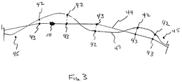
- the inertial measurement unit 26 obtains vehicle state characteristics as the vehicle 10 travels on a vehicle route 47.
- the vehicle state characteristics are forwarded to the inertial converter 27 to provide vehicle state information.
- This vehicle state information may include position information defined as a plurality of measured points 42.
- the measured points 42 may vary from a map route 44 as shown in Figure 3 due to approximation error, map database error, digitization error and the like.
- the map matching module 46 is configured to match each measured point 42 to a matched point 43 on the map route 44.
- the matched points 43 correspond to the measured points 42 and are the most probable locations of the vehicle 10 on the map route 44.
- the position of the vehicle 10 may be updated on the map route 44 at a plurality of positions wherein the location of the vehicle 10 is known with a high level of confidence. These locations may include the end of curves in the map route 44 and recognizable road features.
- the map matching module 46 may additionally be utilized to update heading information of the vehicle 10 with information stored within the map database 34 at positions on the map route 44 wherein the confidence level of the vehicle position is high.
- the vehicle tracking system may further include a plurality of tags 45 or proximity beacons located at a plurality of positions adjacent the vehicle route 47.
- the tags 45 may be passive tags which transmit information in response to an interrogation signal from the vehicle 10 as the vehicle 10 passes each individual tag 45.
- the tags 45 can be transponders.
- Each tag 45 may transmit information including position, velocity, route location, route identification, tag number and the like.
- the vehicle 10 is preferably equipped with a tag receiver 36 for receiving the transmitted vehicle state information from the tag 45 for reducing the error within the vehicle tracking system.
- the tag receiver 36 can be a transponder read device.
- the vehicle tracking system may alternatively include a plurality of tags 45 which are infrared beacons positioned adjacent the vehicle routes 47.
- the tag receiver 36 would therefore include an infrared receiver for receiving the tag information.
- the redundant sensors 30 of the vehicle tracking system may further include a sensor such as an odometer/tachometer 38 for measuring the rotation of a wheel of the vehicle 10.
- the odometer counts the number of rotations of a wheel of the vehicle 10 and may therefore provide distance information as the vehicle 10 travels on the vehicle route 47.
- the tachometer additionally counts the number of rotations over a specified period of time and may provide velocity information of the vehicle 10.
- Each redundant sensor 30 may introduce error into the vehicle tracking system (e.g. error in odometer/tachometer data due to vehicle wheel slippage). Therefore, the vehicle tracking system preferably includes a recursive estimation filter for removing error from the vehicle state information provided by the Global Positioning System 32, map database 34, tag receiver 36, odometer ⁇ tachometer 38, inertial measurement unit 26, and inertial converter 27.
- the clinometers 28 may additionally provide vehicle state information to the Kalman filter 50 during vehicle acceleration.
- the recursive estimation filter can be a Kalman filter 50.
- the vehicle state information from the inertial measurement unit 26 and the redundant sensors 30 may be applied to the Kalman filter 50 as shown in Figure 2.
- the Kalman filter 50 utilizes the vehicle state information in order to estimate sources of error within the vehicle tracking system. In effect, the Kalman filter 50 uses each new vehicle state observation to update a probability distribution for the state of the vehicle.
- the Kalman filter 50 is additionally efficient in operation inasmuch as the filter does not refer back to previous observations of the vehicle state. Accordingly, the Kalman filter 50 is tailored to real-time applications for providing on the spot decision making.
- the Kalman filter 50 may collapse or reduce error within the vehicle tracking system through the processing of vehicle state information from the redundant sensors, inertial measurement unit 26, and inertial converter 27. Furthermore, the Kalman filter 50 is preferably configured to assign independent weights to the vehicle state information provided from each source depending upon the level of confidence in the accuracy of the source.
- the Kalman filter 50 integrates the vehicle state information from the inertial converter 27 and each redundant sensor 30 and provides an output 52 of corrected position, velocity and attitude information.
- the Kalman filter 50 may feedback biases of the inertial measurement unit 26 to correct future output from the inertial converter 27.
- the output 52 of the Kalman filter 50 may additionally be applied to the map matching module 46 which may be utilized for determining the matched points 43.
- the matched points 43 may thereafter be applied to the Kalman filter 50 for integration with the vehicle state information.
- the matched points 43 may additionally be applied to the user interface 20 for displaying the approximate location of the vehicle 10 on the map route 44 or to the transceivers 22, 24 and the fleet management system 40 for remote monitoring.
- the corrected position, velocity and attitude information from the Kalman filter 50 may additionally be applied to the user interface 20 or the transceivers 22, 24 and the fleet management system 40.
- the Kalman filter 50 and the map matching module 46 and the inertial converter 27 may be implemented in a processor 48 for flexibility.
Abstract
An apparatus and method for tracking a vehicle is provided. The vehicle tracking system may include an inertial measurement unit for providing inertial vehicle state characteristics of the vehicle. The inertial measurement unit may include at least one gyro and at least one accelerometer. The vehicle tracking system additionally includes an inertial converter for generating vehicle state information from the inertial vehicle state characteristics. Clinometers are utilized within the vehicle tracking system to initialize the gyros and may additionally provide acceleration information. The vehicle tracking system may additionally include one or more redundant sensors for providing redundant state information. The redundant sensors can include an odometer/tachometer, Global Positioning System receiver, tag receiver, and a map matching system. A Kalman filter may be utilized to reduce error within the vehicle tracking system and improve the accuracy thereof.
Description
- This invention relates generally to the tracking of vehicle motion, and more particularly, to the utilization of redundant vehicle state information and clinometers to provide accurate measurements of the vehicle state in real time.
- The interest in the tracking of land vehicles has recently increased dramatically. Vehicle tracking is an applied science which utilizes a variety of techniques and approaches to determine vehicle state information. The vehicle state information may include present position, velocity, acceleration as well as attitude information.
- For centuries, the position and course of ships were determined by celestial observations and compass readings. Subsequently, similar technology was utilized for aircraft navigation. More recently, radio location systems, inertial measurement systems (IMS), and Global Positioning Systems (GPS) have been utilized to assist with the tracking and navigation of vehicles. In addition, map matching has also been introduced to reduce time based error in vehicle tracking and navigation systems.
- Vehicle tracking and navigation systems provide an abundance of useful information related to the vehicle state. This information may be utilized by the driver for planning the best possible route to reach a particular destination and may include distance and direction information as well as detailed guidance instructions.
- Additionally, the vehicle tracking systems may be utilized in a fleet management system wherein a central control facility remotely monitors the status of individual vehicles. Typical applications include bus schedule control, police car dispatching, and emergency car dispatching. Location and status data may be transmitted between the plurality of vehicles and the central control facility via radio communication.
- Inertial measurement units or guidance systems were developed in Germany during the Second World War. These initial inertial systems were generally utilized for determining desired flight attitude in aircraft and measuring acceleration or thrust along a longitudinal axis.
- More recently, inertial measurement units have been utilized to assist with the tracking and navigation of land vehicles. Specifically, inertial measurement units can monitor the acceleration vector of a land vehicle in motion. The inertial measurement units generally consist of various combinations of inertial sensors including one to three gyros and one to three accelerometers. Additional sensors may be utilized to provide fault tolerant operation.
- The gyros used in the inertial measurement unit measure the angular velocity of the vehicle with respect to inertial space and the accelerometers measure the linear acceleration of the vehicle. The angular orientation of the vehicle may be obtained by integrating the output of the gyros with respect to time. The linear velocity and position of the vehicle may be obtained by integrating the accelerometer output with respect to time and performing appropriate coordinate transformations.
- Some tracking subsystems such as dead reckoning or inertial measurement systems inherently accumulate error over time. While this error may be reduced through various error collapsing schemes, the accuracy of the entire vehicle tracking system will be drastically improved if the error is minimized before the vehicle begins to move.
- Other errors may arise in the vehicle tracking subsystems due to noise in the tracking instruments, processing limitations and errors in the map database if map matching is utilized. Therefore, the accuracy of the vehicle tracking system is greatly improved if an increased amount of vehicle state information, including redundant vehicle state information, is utilized by the vehicle tracking system.
- This invention provides for a vehicle tracking system which preferably utilizes redundant sensor integration for providing error reduction and accurate vehicle state information. In addition, the vehicle tracking system utilizes clinometers for increasing the accuracy of the vehicle tracking system during the initial stages of vehicle movement.
- In particular, the vehicle tracking system in accordance with the present invention includes an inertial measurement unit which includes one or more gyros and one or more accelerometers for providing inertial state characteristics of the vehicle. The vehicle tracking system additionally includes an inertial converter coupled with the inertial measurement unit for obtaining vehicle state information from the inertial state characteristics. One or more clinometers are implemented in the vehicle tracking system for initializing the gyros and providing vehicle acceleration information.
- The vehicle tracking system preferably includes a plurality of redundant sensors coupled with the filter for providing redundant vehicle state information. The redundant sensors can include wheel rotation sensors such as an odometer or tachometer, a Global Positioning System receiver, a tag receiver or a map matching system. The vehicle tracking system preferably includes a recursive estimation filter coupled with the inertial converter and redundant sensors for removing noise from the vehicle state information and outputting corrected vehicle state information.
-
- Figure 1 is a functional block diagram of a vehicle tracking system and a fleet management system;
- Figure 2 is a functional block diagram of a vehicle tracking system in accordance with the present invention; and
- Figure 3 is a diagram of a vehicle travelling on a route.
- The vehicle tracking system according to the present invention provides an apparatus and a method for determining vehicle state information including position, velocity, acceleration, and attitude.
- As shown in Figure 1, the
vehicle 10 is equipped with a plurality of sensors and aprocessor 48 for obtaining vehicle state information. The vehicle state information may be utilized on board thevehicle 10 to inform the driver, via auser interface 20, of present position, velocity and acceleration as well as attitude information. - Alternatively, the
vehicle 10 may include afirst transceiver 22 for transmitting the vehicle state information to asecond transceiver 24 and afleet management system 40 for remote monitoring of thevehicle 10. The vehicle state information may be utilized by thefleet management system 40 to coordinate the dispatching of thevehicles 10 or monitorpublic transportation vehicles 10. - The vehicle tracking system preferably includes an
inertial measurement unit 26 for providing vehicle state information including position, velocity, acceleration and attitude of thevehicle 10. Theinertial measurement unit 26 can include a plurality of inertial sensors including one or more gyros and one or more accelerometers. - Preferably, the
inertial measurement unit 26 consists of a full set of strapdown inertial instruments including three orthogonally oriented gyros and three orthogonally oriented accelerometers. However, theinertial measurement unit 26 provides accurate vehicle state characteristics with three orthogonally oriented gyros and a single accelerometer aligned with the mean direction of the linear vehicle velocity vector. - The accelerometer of the
inertial measurement unit 26 provides the linear velocity of thevehicle 10 while the gyros provide angular rotational rates of the vehicle. The gyros are preferably oriented to provide attitude information including roll, pitch and heading of thevehicle 10. The vehicle state characteristics from theinertial measurement unit 26 may thereafter be forwarded to aninertial converter 27 as shown in Figure 2. - The
inertial converter 27 may be organized into a velocity module and an attitude module. The velocity module of theinertial converter 27 may obtain velocity information of thevehicle 10 by integrating the accelerometer output with respect to time. Further, the position of thevehicle 10 may be approximated by integrating the velocity information with respect to time. - The attitude module may integrate the rotational rate measured by each gyro to provide an instantaneous angular orientation of the
vehicle 10. However, the initial orientation of the vehicle must be known in order to obtain accurate information from the gyros. - Therefore, the vehicle tracking system may include one or
more clinometers 28 for initializing the gyros, and additionally providing vehicle state information. Operating in a static mode, theclinometers 28 measure the angle between the gravity vector and an axis of orientation of theclinometer 28. Preferably, twoclinometers 28 are utilized by the vehicle tracking system for measuring the roll and pitch of thevehicle 10 while the vehicle is not accelerating. The output of theclinometers 28 in the static mode may thereafter be forwarded to theinertial converter 27 for initializing the roll and pitch gyros of theinertial measurement unit 26. - The output of the
clinometers 28 may additionally be processed during a dynamic mode wherein the vehicle is accelerating. The clinometer output approximates the acceleration of thevehicle 10. - The vehicle tracking system may additionally include a plurality of
redundant sensors 30 as shown in Figure 2. Theredundant sensors 30 obtain redundant vehicle state information through a variety of methods to help reduce error within the vehicle tracking system. - The
redundant sensors 30 may include an absolute tracking system such as a Global Positioning System (GPS) 32. The vehicle can be equipped with a Global Positioning System receiver 31 as shown in Figure 1 for receiving position data of thevehicle 10 from theGlobal Positioning System 32. - The use of a
Global Positioning System 32 is advantageous inasmuch as the position data is determined independent of previous data. Therefore, error within theGlobal Positioning System 32 will not increase over a period of time. Additional sensors may be utilized within the vehicle tracking system inasmuch asGlobal Positioning Systems 32 are limited by line-of-sight coverage, weather conditions and terrain characteristics. - The vehicle tracking system may therefore include a map matching system for providing continuous correction of the heading and position of the
vehicle 10 when recognizable road features are identified. An example of a map matching system for collapsing error within the vehicle tracking system is disclosed in the Applicant's United States Patent Application Serial Number 08/518,639, filed August 24, 1995, which is entitled "Map Matching Navigation System". - The map matching system may include a
map database 34 and amap matching module 46 as shown in Figure 2. Map matching systems depend on anaccurate map database 34 in order to provide reliable and useful vehicle state information. Therefore, themap database 34 is preferably generated from numerous sources to eliminate obsolete or inaccurate data. - The operation of a map matching system is shown with reference to Figure 3. In particular, the
inertial measurement unit 26 obtains vehicle state characteristics as thevehicle 10 travels on avehicle route 47. The vehicle state characteristics are forwarded to theinertial converter 27 to provide vehicle state information. This vehicle state information may include position information defined as a plurality of measured points 42. The measured points 42 may vary from amap route 44 as shown in Figure 3 due to approximation error, map database error, digitization error and the like. - The
map matching module 46 is configured to match each measuredpoint 42 to a matchedpoint 43 on themap route 44. The matched points 43 correspond to the measured points 42 and are the most probable locations of thevehicle 10 on themap route 44. Furthermore, the position of thevehicle 10 may be updated on themap route 44 at a plurality of positions wherein the location of thevehicle 10 is known with a high level of confidence. These locations may include the end of curves in themap route 44 and recognizable road features. - The
map matching module 46 may additionally be utilized to update heading information of thevehicle 10 with information stored within themap database 34 at positions on themap route 44 wherein the confidence level of the vehicle position is high. - The vehicle tracking system may further include a plurality of
tags 45 or proximity beacons located at a plurality of positions adjacent thevehicle route 47. Thetags 45 may be passive tags which transmit information in response to an interrogation signal from thevehicle 10 as thevehicle 10 passes eachindividual tag 45. Thetags 45 can be transponders. - Each
tag 45 may transmit information including position, velocity, route location, route identification, tag number and the like. Thevehicle 10 is preferably equipped with atag receiver 36 for receiving the transmitted vehicle state information from thetag 45 for reducing the error within the vehicle tracking system. Thetag receiver 36 can be a transponder read device. - The vehicle tracking system may alternatively include a plurality of
tags 45 which are infrared beacons positioned adjacent thevehicle routes 47. Thetag receiver 36 would therefore include an infrared receiver for receiving the tag information. - The
redundant sensors 30 of the vehicle tracking system may further include a sensor such as an odometer/tachometer 38 for measuring the rotation of a wheel of thevehicle 10. The odometer counts the number of rotations of a wheel of thevehicle 10 and may therefore provide distance information as thevehicle 10 travels on thevehicle route 47. The tachometer additionally counts the number of rotations over a specified period of time and may provide velocity information of thevehicle 10. - Each
redundant sensor 30 may introduce error into the vehicle tracking system (e.g. error in odometer/tachometer data due to vehicle wheel slippage). Therefore, the vehicle tracking system preferably includes a recursive estimation filter for removing error from the vehicle state information provided by theGlobal Positioning System 32,map database 34,tag receiver 36,odometer\tachometer 38,inertial measurement unit 26, andinertial converter 27. Theclinometers 28 may additionally provide vehicle state information to theKalman filter 50 during vehicle acceleration. The recursive estimation filter can be aKalman filter 50. - The vehicle state information from the
inertial measurement unit 26 and theredundant sensors 30 may be applied to theKalman filter 50 as shown in Figure 2. TheKalman filter 50 utilizes the vehicle state information in order to estimate sources of error within the vehicle tracking system. In effect, theKalman filter 50 uses each new vehicle state observation to update a probability distribution for the state of the vehicle. TheKalman filter 50 is additionally efficient in operation inasmuch as the filter does not refer back to previous observations of the vehicle state. Accordingly, theKalman filter 50 is tailored to real-time applications for providing on the spot decision making. - As previously described, the
Kalman filter 50 may collapse or reduce error within the vehicle tracking system through the processing of vehicle state information from the redundant sensors,inertial measurement unit 26, andinertial converter 27. Furthermore, theKalman filter 50 is preferably configured to assign independent weights to the vehicle state information provided from each source depending upon the level of confidence in the accuracy of the source. - As shown in Figure 2, the
Kalman filter 50 integrates the vehicle state information from theinertial converter 27 and eachredundant sensor 30 and provides an output 52 of corrected position, velocity and attitude information. In addition, theKalman filter 50 may feedback biases of theinertial measurement unit 26 to correct future output from theinertial converter 27. The output 52 of theKalman filter 50 may additionally be applied to themap matching module 46 which may be utilized for determining the matched points 43. The matched points 43 may thereafter be applied to theKalman filter 50 for integration with the vehicle state information. - The matched points 43 may additionally be applied to the
user interface 20 for displaying the approximate location of thevehicle 10 on themap route 44 or to thetransceivers fleet management system 40 for remote monitoring. The corrected position, velocity and attitude information from theKalman filter 50 may additionally be applied to theuser interface 20 or thetransceivers fleet management system 40. - The
Kalman filter 50 and themap matching module 46 and theinertial converter 27 may be implemented in aprocessor 48 for flexibility. - While specific embodiments of the invention have been described in detail, it will be appreciated by those skilled in the art that various modifications and alternatives to those details could be developed in light of the overall teachings of the disclosure. Accordingly, the particular arrangements disclosed are meant to be illustrative only and not limiting to the scope of the invention which is to be given the full breadth of the following claims and all equivalents thereof.
Claims (28)
- An apparatus to obtain vehicle state information, comprising:a. an inertial measurement unit including a plurality of inertial sensors to provide a plurality of vehicle state characteristics;b. an inertial converter coupled with said inertial measurement unit to derive inertial vehicle state information from the vehicle state characteristics;c. a filter coupled with said inertial converter to remove error from the inertial vehicle state information and outputting corrected vehicle state information; andd. at least one clinometer coupled with said inertial converter to initialize the vehicle state characteristics.
- The apparatus of claim 1 wherein said at least one clinometer is coupled with said filter to apply dynamic vehicle state information thereto.
- The apparatus of claim 1 wherein the inertial sensors include at least one gyro and at least one accelerometer.
- The apparatus of claim 3 wherein said at least one clinometer initializes a pitch gyro and a roll gyro when the acceleration of the vehicle is zero.
- The apparatus of claim 4 wherein said at least one clinometer is coupled with said filter to apply dynamic vehicle state information thereto.
- The apparatus of claim 1 further comprising a plurality of redundant sensors coupled with said filter to provide redundant vehicle state information.
- The apparatus of claim 6 wherein said redundant sensors include a wheel rotation sensor to provide velocity and distance information, a global positioning system to provide position information, a tag receiver and a plurality of physical tags to provide position and velocity information, and a map matching database and a map matching module to provide position and attitude information.
- The apparatus of claim 7 wherein said inertial converter, said filter, and said map matching module are implemented in a processor.
- The apparatus of claim 7 wherein said at least one clinometer is coupled with said filter to apply dynamic vehicle state information thereto.
- The apparatus of claim 7 wherein the inertial sensors include at least one gyro and at least one accelerometer.
- The apparatus of claim 10 wherein said at least one clinometer initializes a pitch gyro and a roll gyro when the acceleration of the vehicle is zero.
- The apparatus of claim 11 wherein said at least one clinometer is coupled with said filter to apply dynamic vehicle state information thereto.
- The apparatus of claim 9 wherein said filter applies corrected vehicle state information to said inertial converter to update the derived vehicle state information therein.
- The apparatus of claim 13 wherein said filter is a Kalman filter.
- The apparatus of claim 14 wherein said inertial measurement unit includes three orthogonal gyros and one accelerometer.
- The apparatus of claim 15 further comprising a user interface to display corrected vehicle state information.
- The apparatus of claim 16 further comprising a fleet management system to receive and monitoring the corrected vehicle state information.
- A method to determine vehicle state information, comprising the steps of:a. initializing at least one inertial sensor;b. extracting inertial vehicle state information from at least one inertial sensor;c. obtaining redundant vehicle state information from at least one redundant sensor;d. filtering the inertial vehicle state information and the redundant vehicle state information to reduce error therein; ande. determining corrected vehicle state information from the inertial vehicle state information and the redundant vehicle state information.
- The method of claim 18 further comprising the step of updating the position and heading of the vehicle in a map matching system.
- The method of claim 18 wherein the at least one inertial sensor includes three orthogonal gyroscopes and an accelerometer.
- The method of claim 20 wherein said initializing is performed by a clinometer.
- The method of claim 21 further comprising the step of updating the position and heading of the vehicle in a map matching system.
- The method of claim 21 wherein said initializing is performed when the acceleration of the vehicle is zero.
- The method of claim 18 wherein at least one redundant sensor includes a wheel rotation sensor to provide velocity and distance information, a global positioning system to provide position information, a tag receiver and a plurality of tags to provide position and velocity information, and a map matching system to provide position and attitude information.
- The method of claim 24 further comprising the step of updating the position and heading of the vehicle in a map matching system.
- The method of claim 25 wherein the at least one inertial sensor includes three orthogonal gyroscopes and an accelerometer.
- The method of claim 26 wherein said initializing is performed by a clinometer.
- The method of claim 27 wherein the inertial vehicle state information is extracted from the at least one inertial sensor and the filter.
Applications Claiming Priority (2)
| Application Number | Priority Date | Filing Date | Title |
|---|---|---|---|
| US08/518,764 US5902351A (en) | 1995-08-24 | 1995-08-24 | Apparatus and method for tracking a vehicle |
| US518764 | 1995-08-24 |
Publications (1)
| Publication Number | Publication Date |
|---|---|
| EP0762363A1 true EP0762363A1 (en) | 1997-03-12 |
Family
ID=24065402
Family Applications (1)
| Application Number | Title | Priority Date | Filing Date |
|---|---|---|---|
| EP96113315A Withdrawn EP0762363A1 (en) | 1995-08-24 | 1996-08-20 | Apparatus and method for tracking a vehicle |
Country Status (4)
| Country | Link |
|---|---|
| US (1) | US5902351A (en) |
| EP (1) | EP0762363A1 (en) |
| KR (1) | KR970011786A (en) |
| AU (1) | AU714897B2 (en) |
Cited By (21)
| Publication number | Priority date | Publication date | Assignee | Title |
|---|---|---|---|---|
| WO1999004225A1 (en) * | 1997-07-16 | 1999-01-28 | Siemens Aktiengesellschaft | Method for determining the rotating position of a self-contained mobile unit, and self-contained mobile unit |
| WO2000048883A1 (en) * | 1999-02-18 | 2000-08-24 | Continental Teves Ag & Co. Ohg | Sensor system with monitoring device, notably for an esp system for vehicles |
| ES2194615A1 (en) * | 2001-06-11 | 2003-11-16 | Univ Alcala Henares | System and method for checking the speed and locating the position of a vehicle. |
| DE102004029543A1 (en) * | 2004-04-07 | 2005-10-27 | Daimlerchrysler Ag | Vehicle position determination procedure smooths the digital map profile and measured values along possible path using low pass filters |
| DE102005046456A1 (en) * | 2005-09-20 | 2007-03-29 | Siemens Ag | Method for determining the location and / or a movement quantity of moving objects, in particular of moving track-bound vehicles |
| ITBA20090033A1 (en) * | 2009-07-24 | 2009-10-23 | Esim Srl Elettronica Societa Imp Ianti Meridion | TINS SYSTEM - TUNNEL INSPECTION SYSTEM |
| US7860764B1 (en) * | 2000-10-19 | 2010-12-28 | Blaise Alexander | Method and system for leasing motor vehicles to credit challenged consumers |
| CN101265804B (en) * | 2008-05-06 | 2012-07-04 | 上海神开石油化工装备股份有限公司 | Well drilling high precision gradient meter sensor perpendicular installation error compensation process |
| US8462745B2 (en) | 2008-06-16 | 2013-06-11 | Skyhook Wireless, Inc. | Methods and systems for determining location using a cellular and WLAN positioning system by selecting the best WLAN PS solution |
| US8890746B2 (en) | 2010-11-03 | 2014-11-18 | Skyhook Wireless, Inc. | Method of and system for increasing the reliability and accuracy of location estimation in a hybrid positioning system |
| US8994591B2 (en) | 1996-09-09 | 2015-03-31 | Tracbeam Llc | Locating a mobile station and applications therefor |
| US9060341B2 (en) | 1996-09-09 | 2015-06-16 | Tracbeam, Llc | System and method for hybriding wireless location techniques |
| US9134398B2 (en) | 1996-09-09 | 2015-09-15 | Tracbeam Llc | Wireless location using network centric location estimators |
| CN105374224A (en) * | 2015-10-29 | 2016-03-02 | 深圳市元征科技股份有限公司 | Positioning data processing method and vehicle-mounted terminal |
| US9538493B2 (en) | 2010-08-23 | 2017-01-03 | Finetrak, Llc | Locating a mobile station and applications therefor |
| US9875492B2 (en) | 2001-05-22 | 2018-01-23 | Dennis J. Dupray | Real estate transaction system |
| US9885575B2 (en) | 2012-04-04 | 2018-02-06 | Jc Inertial Oy | Vehicle positioning |
| CN107765279A (en) * | 2017-10-17 | 2018-03-06 | 北京航天发射技术研究所 | A kind of fusion inertia, the vehicle positioning directional sighting system and method for sight of satellite |
| DE102017212179A1 (en) * | 2017-07-17 | 2019-01-17 | Siemens Aktiengesellschaft | Correction of a measured position value of a rail-bound vehicle |
| US10641861B2 (en) | 2000-06-02 | 2020-05-05 | Dennis J. Dupray | Services and applications for a communications network |
| US10684350B2 (en) | 2000-06-02 | 2020-06-16 | Tracbeam Llc | Services and applications for a communications network |
Families Citing this family (68)
| Publication number | Priority date | Publication date | Assignee | Title |
|---|---|---|---|---|
| US5902351A (en) * | 1995-08-24 | 1999-05-11 | The Penn State Research Foundation | Apparatus and method for tracking a vehicle |
| DE19536601A1 (en) * | 1995-09-19 | 1997-03-20 | Teldix Gmbh | Navigation system for a vehicle, in particular for a land vehicle |
| US6917968B2 (en) * | 1997-09-30 | 2005-07-12 | Canon Kabushiki Kaisha | System for providing location information from a remote terminal and displaying on a map display as a URL |
| US6374184B1 (en) * | 1999-09-10 | 2002-04-16 | Ge-Harris Railway Electronics, Llc | Methods and apparatus for determining that a train has changed paths |
| AU7828900A (en) | 1999-09-15 | 2001-04-17 | Sirf Technology, Inc. | Navigation system and method for tracking the position of an object |
| EP1147374B1 (en) * | 1999-10-19 | 2012-08-01 | MITAC International Corporation | Portable vehicle navigation system |
| US6609080B1 (en) * | 1999-11-22 | 2003-08-19 | Nokia Mobile Phones Ltd | Multiple-model navigation filter with hybrid positioning |
| US6487992B1 (en) | 1999-11-22 | 2002-12-03 | Robert L. Hollis | Dog behavior monitoring and training apparatus |
| US6477465B1 (en) * | 1999-11-29 | 2002-11-05 | American Gnc Corporation | Vehicle self-carried positioning method and system thereof |
| US7162367B2 (en) * | 1999-11-29 | 2007-01-09 | American Gnc Corporation | Self-contained/interruption-free positioning method and system thereof |
| US6873963B1 (en) | 1999-11-30 | 2005-03-29 | Daimlerchrysler Corporation | Shipment tracking analysis and reporting system (STARS) |
| US6317688B1 (en) * | 2000-01-31 | 2001-11-13 | Rockwell Collins | Method and apparatus for achieving sole means navigation from global navigation satelite systems |
| US6509830B1 (en) | 2000-06-02 | 2003-01-21 | Bbnt Solutions Llc | Systems and methods for providing customizable geo-location tracking services |
| US7142979B1 (en) | 2000-06-21 | 2006-11-28 | Magellan Dis, Inc. | Method of triggering the transmission of data from a mobile asset |
| US6622090B2 (en) * | 2000-09-26 | 2003-09-16 | American Gnc Corporation | Enhanced inertial measurement unit/global positioning system mapping and navigation process |
| US7877286B1 (en) * | 2000-12-20 | 2011-01-25 | Demandtec, Inc. | Subset optimization system |
| US7657470B1 (en) | 2000-12-20 | 2010-02-02 | Demandtec, Inc. | Financial model engine |
| US7660734B1 (en) | 2000-12-20 | 2010-02-09 | Demandtec, Inc. | System for creating optimized promotion event calendar |
| US7617119B1 (en) | 2000-12-20 | 2009-11-10 | Demandtec, Inc. | Price optimization with rule relaxation |
| US7302410B1 (en) * | 2000-12-22 | 2007-11-27 | Demandtec, Inc. | Econometric optimization engine |
| US7523047B1 (en) | 2000-12-20 | 2009-04-21 | Demandtec, Inc. | Price optimization system |
| US9773250B2 (en) | 2000-12-20 | 2017-09-26 | International Business Machines Corporation | Product role analysis |
| US6641090B2 (en) * | 2001-01-10 | 2003-11-04 | Lockheed Martin Corporation | Train location system and method |
| US6691074B1 (en) | 2001-02-08 | 2004-02-10 | Netmore Ltd. | System for three dimensional positioning and tracking |
| EP1386303A1 (en) * | 2001-04-03 | 2004-02-04 | Magellan Dis Inc. | Vehicle navigation system with portable personal computer |
| US20040210541A1 (en) * | 2001-05-04 | 2004-10-21 | Jeremy Epstien | User interface for a rules engine and methods therefor |
| US6604047B1 (en) | 2001-08-03 | 2003-08-05 | Scott C. Harris | Non real time traffic system for a navigator |
| US6995689B2 (en) * | 2001-10-10 | 2006-02-07 | Crank Kelly C | Method and apparatus for tracking aircraft and securing against unauthorized access |
| IL161333A0 (en) * | 2001-10-10 | 2004-09-27 | Mcloughlin Pacific Corp | Method and apparatus for tracking aircraft and securing against unauthorized access |
| US7386519B1 (en) | 2001-11-30 | 2008-06-10 | Demandtec, Inc. | Intelligent clustering system |
| US7809581B1 (en) | 2001-11-30 | 2010-10-05 | Demandtec, Inc. | Rule relaxation and subset optimization system |
| US6812887B2 (en) * | 2001-12-12 | 2004-11-02 | Nokia Corporation | Method and apparatus for saving power in a global positioning system receiver |
| US6925413B2 (en) * | 2001-12-14 | 2005-08-02 | Robert Bosch Gmbh | Method and system for detecting a spatial movement state of moving objects |
| US20040140405A1 (en) * | 2002-01-10 | 2004-07-22 | Meyer Thomas J. | Train location system and method |
| US7209810B2 (en) * | 2002-01-10 | 2007-04-24 | Lockheed Martin Corp. | Locomotive location system and method |
| US6826478B2 (en) * | 2002-04-12 | 2004-11-30 | Ensco, Inc. | Inertial navigation system for mobile objects with constraints |
| US6757641B1 (en) | 2002-06-28 | 2004-06-29 | The United States Of America As Represented By The Administrator Of The National Aeronautics And Space Administration | Multi sensor transducer and weight factor |
| US7409188B2 (en) * | 2003-11-26 | 2008-08-05 | Nokia Corporation | Method and apparatus for lowering power use by a ranging receiver |
| TWI271536B (en) * | 2005-06-27 | 2007-01-21 | Lite On Technology Corp | Position indicating system |
| US7103477B1 (en) * | 2005-08-08 | 2006-09-05 | Northrop Grumman Corporation | Self-calibration for an inertial instrument based on real time bias estimator |
| KR100753933B1 (en) | 2005-12-29 | 2007-08-31 | 에스케이에너지 주식회사 | Method, system and server for selecting location and user terminal |
| US9785951B1 (en) | 2006-02-28 | 2017-10-10 | International Business Machines Corporation | Scalable tuning engine |
| US9858579B1 (en) | 2006-02-28 | 2018-01-02 | International Business Machines Corporation | Plan tuning engine |
| US7328104B2 (en) * | 2006-05-17 | 2008-02-05 | Honeywell International Inc. | Systems and methods for improved inertial navigation |
| JP4341649B2 (en) * | 2006-07-12 | 2009-10-07 | トヨタ自動車株式会社 | Navigation device and position detection method |
| US8471906B2 (en) * | 2006-11-24 | 2013-06-25 | Trex Enterprises Corp | Miniature celestial direction detection system |
| US20120116711A1 (en) * | 2007-09-13 | 2012-05-10 | Trex Enterprises Corp. | Portable celestial compass |
| US8401238B2 (en) * | 2007-05-29 | 2013-03-19 | Continental Teves Ag & Co. Ohg | Map matching for security applications |
| US20090058723A1 (en) * | 2007-09-04 | 2009-03-05 | Mediatek Inc. | Positioning system and method thereof |
| US7966126B2 (en) * | 2008-02-15 | 2011-06-21 | Ansaldo Sts Usa, Inc. | Vital system for determining location and location uncertainty of a railroad vehicle with respect to a predetermined track map using a global positioning system and other diverse sensors |
| AP2011006008A0 (en) * | 2009-05-01 | 2011-12-31 | Univ Sydney | Integrated automation system with picture compilation system. |
| AU2010242540B2 (en) | 2009-05-01 | 2016-01-14 | Technological Resources Pty. Limited | Integrated automation system |
| US8296065B2 (en) * | 2009-06-08 | 2012-10-23 | Ansaldo Sts Usa, Inc. | System and method for vitally determining position and position uncertainty of a railroad vehicle employing diverse sensors including a global positioning system sensor |
| JP4793479B2 (en) * | 2009-07-09 | 2011-10-12 | カシオ計算機株式会社 | Positioning device, positioning method and program |
| US8922426B1 (en) * | 2010-02-26 | 2014-12-30 | Google Inc. | System for geo-location |
| US8442763B2 (en) * | 2010-04-16 | 2013-05-14 | CSR Technology Holdings Inc. | Method and apparatus for geographically aiding navigation satellite system solution |
| US9135816B2 (en) * | 2011-09-08 | 2015-09-15 | Laser Technology, Inc. | Intelligent laser tracking system and method for mobile and fixed position traffic monitoring and enforcement applications |
| KR20140093961A (en) * | 2011-10-24 | 2014-07-29 | 콘티넨탈 테베스 아게 운트 코. 오하게 | Sensor system for independently evaluating the accuracy of the data of the sensor system |
| WO2013188911A1 (en) | 2012-06-18 | 2013-12-27 | The University Of Sydney | Systems and methods for processing geophysical data |
| EP3005333A1 (en) * | 2013-05-27 | 2016-04-13 | Ekin Teknoloji Sanayi ve Ticaret Anonim Sirketi | Mobile number plate recognition and speed detection system |
| CN104154916B (en) * | 2013-08-30 | 2018-11-30 | 北京航天发射技术研究所 | A kind of vehicle positioning equipment based on the used group of laser gyro strap down |
| EP3594086A3 (en) | 2015-03-05 | 2020-05-06 | Thales Canada Inc. | Guideway mounted vehicle localization system |
| WO2016153435A1 (en) * | 2015-03-26 | 2016-09-29 | Agency for Science,Technology and Research | Location system and method for determining location of a vehicle |
| FR3068478B1 (en) | 2017-06-30 | 2021-12-31 | Deutsches Zentrum Fuer Luft & Raumfahrt Ev | METHOD FOR DETERMINING THE POSITION OF A RAILWAY VEHICLE IN A RAILWAY NETWORK |
| JP7074438B2 (en) * | 2017-09-05 | 2022-05-24 | トヨタ自動車株式会社 | Vehicle position estimation device |
| SE542743C2 (en) * | 2018-11-06 | 2020-07-07 | Mobilaris Mce Ab | Method and device for determining the position of a moving object |
| DE102021204372A1 (en) | 2021-04-30 | 2022-11-03 | Siemens Mobility GmbH | Orientation-based position determination of rail vehicles |
| CN113884098B (en) * | 2021-10-15 | 2024-01-23 | 上海师范大学 | Iterative Kalman filtering positioning method based on materialization model |
Citations (4)
| Publication number | Priority date | Publication date | Assignee | Title |
|---|---|---|---|---|
| DE3439000A1 (en) * | 1984-10-25 | 1986-04-30 | Teldix Gmbh, 6900 Heidelberg | Integrated-navigation device |
| WO1991009375A1 (en) * | 1989-12-11 | 1991-06-27 | Caterpillar Inc. | Integrated vehicle positioning and navigation system, apparatus and method |
| EP0605848A1 (en) * | 1992-12-28 | 1994-07-13 | UNION SWITCH & SIGNAL Inc. | Traffic control system utilizing on-board vehicle information measurement apparatus |
| US5422815A (en) * | 1992-12-14 | 1995-06-06 | Pioneer Electronic Corporation | Navigation apparatus and navigation method |
Family Cites Families (35)
| Publication number | Priority date | Publication date | Assignee | Title |
|---|---|---|---|---|
| US4032759A (en) * | 1975-10-24 | 1977-06-28 | The Singer Company | Shipboard reference for an aircraft navigation system |
| US4321678A (en) * | 1977-09-14 | 1982-03-23 | Bodenseewerk Geratetechnik Gmbh | Apparatus for the automatic determination of a vehicle position |
| JPH0644184B2 (en) * | 1985-03-11 | 1994-06-08 | 日産自動車株式会社 | Vehicle route guidance device |
| JPS61209316A (en) * | 1985-03-14 | 1986-09-17 | Nissan Motor Co Ltd | Route guide apparatus for vehicle |
| CA1254628A (en) * | 1985-04-19 | 1989-05-23 | Akira Iihoshi | Device for displying travel path of motor vehicle |
| DE3519276A1 (en) * | 1985-05-30 | 1986-12-04 | Robert Bosch Gmbh, 7000 Stuttgart | NAVIGATION SYSTEM FOR VEHICLES |
| DE3621953A1 (en) * | 1986-06-30 | 1988-01-14 | Bodenseewerk Geraetetech | INERTIA SENSOR ARRANGEMENT |
| DE3634023A1 (en) * | 1986-10-07 | 1988-04-21 | Bodenseewerk Geraetetech | INTEGRATED, REDUNDANT REFERENCE SYSTEM FOR FLIGHT CONTROL AND FOR GENERATING COURSE AND LOCATION INFORMATION |
| DE3736386A1 (en) * | 1986-10-27 | 1988-07-14 | Pioneer Electronic Corp | VEHICLE BORING PROCESS |
| US4800501A (en) * | 1986-11-24 | 1989-01-24 | Ivan Kinsky | Vehicle land navigating device |
| US4879658A (en) * | 1987-02-10 | 1989-11-07 | Yazaki Corporation | Navigation system using angular rate sensor |
| JP2680312B2 (en) * | 1987-07-10 | 1997-11-19 | アイシン・エィ・ダブリュ株式会社 | Vehicle navigation system |
| JPH01214711A (en) * | 1988-02-23 | 1989-08-29 | Toshiba Corp | Navigation apparatus |
| JPH023900A (en) * | 1988-06-16 | 1990-01-09 | Nissan Motor Co Ltd | Present place displaying device for moving body |
| JPH07119617B2 (en) * | 1988-07-05 | 1995-12-20 | マツダ株式会社 | Vehicle navigation system |
| JPH0278907A (en) * | 1988-09-16 | 1990-03-19 | Hitachi Ltd | Navigation system using map data and location system for moving body |
| US5060162A (en) * | 1988-12-09 | 1991-10-22 | Matsushita Electric Industrial Co., Ltd. | Vehicle in-situ locating apparatus |
| US5012424A (en) * | 1989-02-22 | 1991-04-30 | Honeywell Inc. | Multiple sensor system and method |
| US5166882A (en) * | 1989-03-31 | 1992-11-24 | The United States Of America As Represented By The Secretary Of The Navy | System for calibrating a gyro navigator |
| US5075673A (en) * | 1989-06-16 | 1991-12-24 | International Business Machines Corp. | Variable speed, image pan method and apparatus |
| US5297052A (en) * | 1989-10-16 | 1994-03-22 | The Boeing Company | Integrated fault-tolerant air data inertial reference system |
| US5177685A (en) * | 1990-08-09 | 1993-01-05 | Massachusetts Institute Of Technology | Automobile navigation system using real time spoken driving instructions |
| EP0485132B1 (en) * | 1990-11-06 | 1996-03-06 | Fujitsu Ten Limited | Direction sensor having an earth magnetism sensor and a rate gyro sensor and navigation system having this direction sensor |
| US5194872A (en) * | 1990-11-14 | 1993-03-16 | Charles Stark Draper Laboratory, Inc. | Inertial navigation system with automatic redundancy and dynamic compensation of gyroscope drift error |
| US5051751A (en) * | 1991-02-12 | 1991-09-24 | The United States Of America As Represented By The Secretary Of The Navy | Method of Kalman filtering for estimating the position and velocity of a tracked object |
| US5184304A (en) * | 1991-04-26 | 1993-02-02 | Litton Systems, Inc. | Fault-tolerant inertial navigation system |
| US5311195A (en) * | 1991-08-30 | 1994-05-10 | Etak, Inc. | Combined relative and absolute positioning method and apparatus |
| US5283575A (en) * | 1991-11-08 | 1994-02-01 | Zexel Corporation | System and method for locating a travelling vehicle |
| US5152239A (en) * | 1991-11-19 | 1992-10-06 | Raytheon Company | Autopilot having roll compensation capabilities |
| US5311435A (en) * | 1991-11-27 | 1994-05-10 | Hughes Aircraft Company | Method for station keeping control of flexible spacecraft using onboard gain scheduling scheme |
| JP2611592B2 (en) * | 1991-12-09 | 1997-05-21 | 三菱電機株式会社 | Navigation apparatus for mobile object and display method thereof |
| US5394333A (en) * | 1991-12-23 | 1995-02-28 | Zexel Usa Corp. | Correcting GPS position in a hybrid naviation system |
| JPH0731062B2 (en) * | 1992-02-10 | 1995-04-10 | 住友電気工業株式会社 | Gyro offset correction method and apparatus |
| US5574650A (en) * | 1993-03-23 | 1996-11-12 | Litton Systems, Inc. | Method and apparatus for calibrating the gyros of a strapdown inertial navigation system |
| US5902351A (en) * | 1995-08-24 | 1999-05-11 | The Penn State Research Foundation | Apparatus and method for tracking a vehicle |
-
1995
- 1995-08-24 US US08/518,764 patent/US5902351A/en not_active Expired - Fee Related
-
1996
- 1996-08-16 AU AU62124/96A patent/AU714897B2/en not_active Ceased
- 1996-08-20 EP EP96113315A patent/EP0762363A1/en not_active Withdrawn
- 1996-08-24 KR KR1019960035484A patent/KR970011786A/en not_active Application Discontinuation
Patent Citations (4)
| Publication number | Priority date | Publication date | Assignee | Title |
|---|---|---|---|---|
| DE3439000A1 (en) * | 1984-10-25 | 1986-04-30 | Teldix Gmbh, 6900 Heidelberg | Integrated-navigation device |
| WO1991009375A1 (en) * | 1989-12-11 | 1991-06-27 | Caterpillar Inc. | Integrated vehicle positioning and navigation system, apparatus and method |
| US5422815A (en) * | 1992-12-14 | 1995-06-06 | Pioneer Electronic Corporation | Navigation apparatus and navigation method |
| EP0605848A1 (en) * | 1992-12-28 | 1994-07-13 | UNION SWITCH & SIGNAL Inc. | Traffic control system utilizing on-board vehicle information measurement apparatus |
Non-Patent Citations (1)
| Title |
|---|
| HALL H H: "Alternate approaches to automotive navigation", TRANSPORTATION ELECTRONICS: PROCEEDINGS OF THE INTERNATIONAL CONGRESS ON TRANSPORTATION ELECTRONICS (P-183), DEARBORN, MI, USA, 20-22 OCT. 1986, ISBN 0-89883-747-2, OCT. 1986, WARRENDALE, PA, USA, SAE, USA, pages 211 - 217, XP002019468 * |
Cited By (32)
| Publication number | Priority date | Publication date | Assignee | Title |
|---|---|---|---|---|
| US9237543B2 (en) | 1996-09-09 | 2016-01-12 | Tracbeam, Llc | Wireless location using signal fingerprinting and other location estimators |
| US9060341B2 (en) | 1996-09-09 | 2015-06-16 | Tracbeam, Llc | System and method for hybriding wireless location techniques |
| US9134398B2 (en) | 1996-09-09 | 2015-09-15 | Tracbeam Llc | Wireless location using network centric location estimators |
| US9277525B2 (en) | 1996-09-09 | 2016-03-01 | Tracbeam, Llc | Wireless location using location estimators |
| US8994591B2 (en) | 1996-09-09 | 2015-03-31 | Tracbeam Llc | Locating a mobile station and applications therefor |
| WO1999004225A1 (en) * | 1997-07-16 | 1999-01-28 | Siemens Aktiengesellschaft | Method for determining the rotating position of a self-contained mobile unit, and self-contained mobile unit |
| WO2000048883A1 (en) * | 1999-02-18 | 2000-08-24 | Continental Teves Ag & Co. Ohg | Sensor system with monitoring device, notably for an esp system for vehicles |
| US6625527B1 (en) | 1999-02-18 | 2003-09-23 | Continental Teves Ag & Co. Ohg | Sensor system with monitoring device |
| US10641861B2 (en) | 2000-06-02 | 2020-05-05 | Dennis J. Dupray | Services and applications for a communications network |
| US10684350B2 (en) | 2000-06-02 | 2020-06-16 | Tracbeam Llc | Services and applications for a communications network |
| US7860764B1 (en) * | 2000-10-19 | 2010-12-28 | Blaise Alexander | Method and system for leasing motor vehicles to credit challenged consumers |
| US9875492B2 (en) | 2001-05-22 | 2018-01-23 | Dennis J. Dupray | Real estate transaction system |
| US11610241B2 (en) | 2001-05-22 | 2023-03-21 | Mobile Maven Llc | Real estate transaction system |
| ES2194615A1 (en) * | 2001-06-11 | 2003-11-16 | Univ Alcala Henares | System and method for checking the speed and locating the position of a vehicle. |
| DE102004029543B4 (en) * | 2004-04-07 | 2006-09-07 | Daimlerchrysler Ag | Method for determining the position of a vehicle by multi-channel profile map matching |
| DE102004029543A1 (en) * | 2004-04-07 | 2005-10-27 | Daimlerchrysler Ag | Vehicle position determination procedure smooths the digital map profile and measured values along possible path using low pass filters |
| DE102005046456B4 (en) * | 2005-09-20 | 2007-06-06 | Siemens Ag | Method for determining the location and / or a movement quantity of moving objects, in particular of moving track-bound vehicles |
| DE102005046456A1 (en) * | 2005-09-20 | 2007-03-29 | Siemens Ag | Method for determining the location and / or a movement quantity of moving objects, in particular of moving track-bound vehicles |
| CN101265804B (en) * | 2008-05-06 | 2012-07-04 | 上海神开石油化工装备股份有限公司 | Well drilling high precision gradient meter sensor perpendicular installation error compensation process |
| US8638725B2 (en) | 2008-06-16 | 2014-01-28 | Skyhook Wireless, Inc. | Methods and systems for determining location using a cellular and WLAN positioning system by selecting the best WLAN PS solution |
| US8462745B2 (en) | 2008-06-16 | 2013-06-11 | Skyhook Wireless, Inc. | Methods and systems for determining location using a cellular and WLAN positioning system by selecting the best WLAN PS solution |
| ITBA20090033A1 (en) * | 2009-07-24 | 2009-10-23 | Esim Srl Elettronica Societa Imp Ianti Meridion | TINS SYSTEM - TUNNEL INSPECTION SYSTEM |
| US9538493B2 (en) | 2010-08-23 | 2017-01-03 | Finetrak, Llc | Locating a mobile station and applications therefor |
| US10849089B2 (en) | 2010-08-23 | 2020-11-24 | Finetrak, Llc | Resource allocation according to geolocation of mobile communication units |
| US8890746B2 (en) | 2010-11-03 | 2014-11-18 | Skyhook Wireless, Inc. | Method of and system for increasing the reliability and accuracy of location estimation in a hybrid positioning system |
| US9885575B2 (en) | 2012-04-04 | 2018-02-06 | Jc Inertial Oy | Vehicle positioning |
| CN105374224B (en) * | 2015-10-29 | 2018-04-10 | 深圳市元征科技股份有限公司 | A kind of location data processing method and car-mounted terminal |
| CN105374224A (en) * | 2015-10-29 | 2016-03-02 | 深圳市元征科技股份有限公司 | Positioning data processing method and vehicle-mounted terminal |
| DE102017212179A1 (en) * | 2017-07-17 | 2019-01-17 | Siemens Aktiengesellschaft | Correction of a measured position value of a rail-bound vehicle |
| WO2019015997A1 (en) | 2017-07-17 | 2019-01-24 | Siemens Aktiengesellschaft | Correction of a measured position value of a rail-based vehicle |
| CN107765279A (en) * | 2017-10-17 | 2018-03-06 | 北京航天发射技术研究所 | A kind of fusion inertia, the vehicle positioning directional sighting system and method for sight of satellite |
| CN107765279B (en) * | 2017-10-17 | 2020-08-07 | 北京航天发射技术研究所 | Vehicle-mounted positioning and directional aiming system and method integrating inertia and satellite |
Also Published As
| Publication number | Publication date |
|---|---|
| AU714897B2 (en) | 2000-01-13 |
| US5902351A (en) | 1999-05-11 |
| KR970011786A (en) | 1997-03-27 |
| AU6212496A (en) | 1997-02-27 |
Similar Documents
| Publication | Publication Date | Title |
|---|---|---|
| US5902351A (en) | Apparatus and method for tracking a vehicle | |
| EP1478903B1 (en) | Device for use with a portable inertial navigation system (pins) and method for processing pins signals | |
| CN109931944B (en) | AR navigation method, AR navigation device, vehicle-side equipment, server side and medium | |
| EP0359287B1 (en) | Navigation system and method using map data | |
| US7349802B2 (en) | Apparatus and method for detecting vehicle location in navigation system | |
| CN101907714B (en) | GPS aided positioning system and method based on multi-sensor data fusion | |
| EP0566391B1 (en) | Apparatus for detecting the position of a vehicle | |
| CN102089624A (en) | Method and systems for the building up of a roadmap and for the determination of the position of a vehicle | |
| JP2000502802A (en) | Improved vehicle navigation system and method utilizing GPS speed | |
| US6349259B1 (en) | Navigation apparatus and information generating apparatus | |
| JP4652097B2 (en) | Altitude calculation device and navigation device | |
| JP2001221652A (en) | Inertial guide apparatus and method for navigation system for car | |
| EP3667235A1 (en) | Segmented path coordinate system | |
| WO2000050917A1 (en) | Vehicle navigation system with correction for selective availability | |
| WO2002091014A2 (en) | A gps based terrain referenced navigation system | |
| CN114323003A (en) | Underground mine fusion positioning method based on UMB, IMU and laser radar | |
| CN112525207B (en) | Unmanned vehicle positioning method based on vehicle pitch angle map matching | |
| JPH04138317A (en) | Navigation apparatus utilizing communication between vehicles | |
| EP0763712A1 (en) | Vehicle navigator system | |
| RU2293950C1 (en) | Flying vehicle navigation complex | |
| US6473689B1 (en) | Method for navigating a vehicle | |
| Wachsmuth et al. | Development of an error-state Kalman Filter for Emergency Maneuvering of Trucks | |
| MXPA96004150A (en) | Navigating system vehicu | |
| JPH01161111A (en) | Navigation device for moving body | |
| US20040148097A1 (en) | Transmission of vehicle position relative to map database |
Legal Events
| Date | Code | Title | Description |
|---|---|---|---|
| PUAI | Public reference made under article 153(3) epc to a published international application that has entered the european phase |
Free format text: ORIGINAL CODE: 0009012 |
|
| AK | Designated contracting states |
Kind code of ref document: A1 Designated state(s): DE ES FR GB IE IT NL PT SE |
|
| 17P | Request for examination filed |
Effective date: 19970612 |
|
| 17Q | First examination report despatched |
Effective date: 19991117 |
|
| GRAG | Despatch of communication of intention to grant |
Free format text: ORIGINAL CODE: EPIDOS AGRA |
|
| STAA | Information on the status of an ep patent application or granted ep patent |
Free format text: STATUS: THE APPLICATION IS DEEMED TO BE WITHDRAWN |
|
| 18D | Application deemed to be withdrawn |
Effective date: 20010301 |