EP0762244A2 - Elektronische Zeitschalter - Google Patents
Elektronische Zeitschalter Download PDFInfo
- Publication number
- EP0762244A2 EP0762244A2 EP96401874A EP96401874A EP0762244A2 EP 0762244 A2 EP0762244 A2 EP 0762244A2 EP 96401874 A EP96401874 A EP 96401874A EP 96401874 A EP96401874 A EP 96401874A EP 0762244 A2 EP0762244 A2 EP 0762244A2
- Authority
- EP
- European Patent Office
- Prior art keywords
- time
- microprocessor
- switch
- switching
- date
- Prior art date
- Legal status (The legal status is an assumption and is not a legal conclusion. Google has not performed a legal analysis and makes no representation as to the accuracy of the status listed.)
- Granted
Links
- 230000001419 dependent effect Effects 0.000 claims abstract description 3
- 230000036962 time dependent Effects 0.000 claims description 4
- 230000001186 cumulative effect Effects 0.000 claims description 2
- 238000000034 method Methods 0.000 description 3
- 238000010276 construction Methods 0.000 description 2
- 239000013078 crystal Substances 0.000 description 2
- 230000005540 biological transmission Effects 0.000 description 1
- 238000010586 diagram Methods 0.000 description 1
- 230000005611 electricity Effects 0.000 description 1
- 230000006870 function Effects 0.000 description 1
- 238000010438 heat treatment Methods 0.000 description 1
- 239000004973 liquid crystal related substance Substances 0.000 description 1
- 238000004519 manufacturing process Methods 0.000 description 1
- 238000012986 modification Methods 0.000 description 1
- 230000004048 modification Effects 0.000 description 1
- 238000003825 pressing Methods 0.000 description 1
- 239000010453 quartz Substances 0.000 description 1
- VYPSYNLAJGMNEJ-UHFFFAOYSA-N silicon dioxide Inorganic materials O=[Si]=O VYPSYNLAJGMNEJ-UHFFFAOYSA-N 0.000 description 1
- 230000000007 visual effect Effects 0.000 description 1
Images

Classifications
-
- G—PHYSICS
- G04—HOROLOGY
- G04G—ELECTRONIC TIME-PIECES
- G04G9/00—Visual time or date indication means
- G04G9/0076—Visual time or date indication means in which the time in another time-zone or in another city can be displayed at will
-
- G—PHYSICS
- G04—HOROLOGY
- G04G—ELECTRONIC TIME-PIECES
- G04G15/00—Time-pieces comprising means to be operated at preselected times or after preselected time intervals
- G04G15/006—Time-pieces comprising means to be operated at preselected times or after preselected time intervals for operating at a number of different times
Definitions
- This invention relates to electronic time switches.
- an electronic time switch comprising at least one switching device, a reference frequency source, a microprocessor and means for applying to the microprocessor inputs representative of at least the current time and date and the latitude at which the time switch is to be used, the microprocessor being responsive to the reference frequency source and the current time and date inputs to implement a real time clock and calendar, and being arranged to calculate from the date provided by said real time clock and calendar and from the latitude input the respective times of at least one of sunrise and sunset at said location on each of a plurality of days, and to operate the switching device at respective switching times dependent upon the calculated times.
- the input applying means is arranged to apply to the microprocessor a further input representative of the longitude at which the time switch is to be used, and the microprocessor is arranged to calculate said respective times in dependence upon said longitude as well as said latitude and time and date.
- the microprocessor is arranged to switch the switching device on at a switching time dependent upon or equal to the calculated time of sunset and to switch the switching device off at a switching time dependent upon or equal to the calculated time of sunrise.
- the microprocessor is programmable to switch the switching device off and back on again at respective selected times between the calculated time of sunset and the calculated time of the immediately subsequent sunrise.
- the time switch includes two switching devices which are independently operable by the microprocessor in dependence upon said calculated times in accordance with a first and a second daily switching programme respectively, the microprocessor being arranged to alternate the application of said switching programmes between the switching devices so as to tend to maintain their respective cumulative on periods substantially equal.
- the time switch of Figure 1 is indicated at 10, and has a substantially circular body 12.
- the time switch 10 is of substantially the same diameter as the well-known SANGAMO round pattern time switch, which has been manufactured in various electromechanical (and latterly electronic) forms by the present applicant and its predecessors over the last sixty years: more specifically, the time switch 10 is designed to plug into the same type of standard socket used for the round pattern time switch, this socket being hard-wired to the light(s) and/or other electrical appliance(s) to be controlled by the time switch.
- the time switch 10 is microprocessor-controlled, and its front face 14 includes a rectangular liquid crystal display (LCD) 16 controlled by the microprocessor.
- the LCD 16 is similar (but not identical) to the display which forms the subject of our United Kingdom Patent No 2 149 153, in that it has an analogue display 18, comprising an oval array of energisable indicia 20, and a digital display 22 comprising a four digit, seven segment numerical display for displaying time in a 12-hour or 24-hour clock format.
- the LCD 16 also has various auxiliary displays which are energised during programming or normal operation of the time switch 10, as will also become apparent hereinafter.
- the front face 14 of the time switch 10 is also provided with six control buttons 31 to 36 for programming the operation of the time switch via the microprocessor, four of these buttons (31 to 34) being disposed in a line immediately beneath the LCD 16 and the other two (35, 36) being positioned one each side of the LCD 16.
- Each of the buttons 35, 36 has a light-emitting diode (LED), 38, 40 respectively, just above it.
- the front face 14 of the time switch 10 includes a pull-out handle 42 by means of which the time switch can be unlocked and withdrawn from the aforementioned socket, while the circular body 12 is provided with two diametrically opposed, radially extending locating pips 44 which ensure the accurate alignment of the body 12 with the socket.
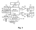
- the circuitry of the time switch 10 is based upon a microprocessor, which is indicated at 50 in Figure 2.
- the microprocessor 50 belongs to the H8/300L series of microprocessors, manufactured by Hitachi.
- the microprocessor 50 has first and second clock inputs 52, 54.
- the input 52 is connected to the output of a 10MHz clock oscillator 56, which controls the operating speed of the microprocessor, while the input 54 is connected to the output of a clock oscillator 58 based upon a highly stable 32Khz quartz crystal (ie a watch crystal) 60.
- the clock input 54 is connected internally of the microprocessor 50 to a real time clock circuit 62, which, once set to the correct real time (including day of the month and year), maintains real time accurately in known manner: typically, the real time clock circuit is programmed to correctly account for leap years for the next 100 years.
- the microprocessor 50 has a further set of inputs 64 connected to the aforementioned buttons 31 to 36 and to an input device such as a microswitch (not shown) operated by an override button provided in the aforementioned socket, as well as power supply inputs 66 connected to the output of a DC power supply circuit 68.
- an input device such as a microswitch (not shown) operated by an override button provided in the aforementioned socket, as well as power supply inputs 66 connected to the output of a DC power supply circuit 68.
- the power supply circuit 68 is powered from the 50Hz or 60Hz mains power supply which the time switch is arranged to switch in order to turn the aforementioned light(s) and/or appliance(s) on and off at programmed times, and includes a battery back-up circuit which maintains the operation of the essential functions of the microprocessor 50, in particular the real time clock circuit 62 and the memory containing the data for calculating the programmed switching times, in the event of a failure of the mains power supply.
- the time switch 10 is a two-channel time switch. To this end, it has two independently controllable output relays 70, 72, one for each channel, which control the supply of mains power to respective ones of the aforementioned light(s) and/or other appliance(s) controlled by it.
- the relays 70, 72 are controlled in turn by the microprocessor 50, which has respective control outputs 74, 76 connected to the relays 70, 72 via respective amplifiers 78, 80.
- the amplifiers 78, 80 are also connected to energise the LEDs 38, 40.
- a further set of outputs 82 of the microprocessor 50 control the LCD 16.
- buttons 35 and 36 act as increment and decrement buttons to increase or decrease the displayed values on the LCD 16 in this mode, and are used to set the real time by successively setting up hours, minutes, am/pm (unless a 24 hour time system is in use), day of the month, month and year, each of these being entered by pressing the button 34, which is called the ACCEPT button, when the desired value is displayed on the LCD.
- the microprocessor 50 calculates in known manner the day of the week on the entered date, and the LCD 16 displays that as well.
- the LCD 16 then displays latitude, from -90° to +90°, the correct value for the location of use of the time switch 10 being selected using the buttons 35, 36 and entered using the ACCEPT button 34. An analogous procedure is then followed to select and enter the correct value of the longitude, between -180° and +180°, for the location of use of the time switch 10.
- the user will enter local "standard time”. As described below, the difference between the time zone of the user and the GMT time zone (if any) will be compensated for by an offset introduced during the setting-up.
- the time switch 10 contains all its required set-up data, and the MODE button 31 is pressed to enter all this data, ie the selected real time and location of use data, into the memory of the microprocessor 50 and to simultaneously set the time switch to its program mode.
- any daylight saving offset should be ignored, and in countries where the "standard time” includes such an offset or an offset due to the geographical position of a national boundary (ie a time zone change), the offset can be separately entered during the setting-up process so that the calculation takes account of it.
- the offset will be subtracted from the entered time zone to enable the calculation to be carried out in GMT and then added to the end result to convert the sunrise and sunset times to local time.
- This time zone offset correction is of course carried out in addition to the longitudinal correction using the offset correction factor ⁇ described above.
- the microprocessor 50 In its factory-programmed state, the microprocessor 50 is programmed to switch the relays 70, 72 off at the calculated sunrise time each day, and on at the calculated sunset time each day. So if the user is happy with this program, he or she need do no further programming, and can simply press the MODE button 31 to set the time switch 10 to its run (or normal) mode, in which it will operate the relays 70, 72 at sunrise and sunset.
- buttons 35, 36 act as channel select buttons, and operation of either of them serves to switch the time switch back and forth between the two channels.
- the data entered is clearly relevant to, and used in the operation of, both channels. But when the time switch 10 is set to the program mode, that mode is applicable only to whichever one of the two channels was selected prior to entry into the set-up mode, and the user can then change the factory-set program for the selected channel.
- the user can select an "Early Off” time, in which the microprocessor 50, having switched the relay 70 or 72 on at sunset, will switch it off again at a programmed time before sunrise.
- an "Early Off” display among the aforementioned auxiliary displays of the LCD 16 is energised, and the user can select a desired off time using the buttons 35, 36 and enter it using the button 34.
- an "Early On” display among the auxiliary displays of the LCD 16 is energised, and the user can if desired select a time earlier than sunrise for the microprocessor 50, having switched the relay 70 or 72 off at a selected "Early Off” time, to switch it back on again.
- buttons 32 and 33 are used during programming to omit certain days (eg weekends) from the programmed switching times, and to cancel incorrect entries, respectively.
- the analogue display 18 in the LCD 16 which analogue display represents a 24 hour clock face, displays the selected time periods for which the relay 70 or 72 of the currently selected channel will be switched on by energising groups of adjacent indicia corresponding to the time periods (so these time periods can be seen to change as programming progresses).
- the analogue display 18 will continue to display the time periods for which the relay 70 or 72 of the currently selected channel is programmed to be switched on, while the digital display 22 will display the current real time in 12- or 24-hour format. And when either of the relays 70, 72 is actually switched on, the respective ones of the LEDs 38, 40 will be energised to provide a visual indication of that fact.
- Operation of the aforementioned override button while the time switch 10 is in its normal mode switches the relay 70 or 72 of the currently selected channel off if it is currently on, with normal operation resuming at the next programmed on time. However, if the relevant one of the relays 70, 72 is currently off, operation of the override button switches it on, either for a predetermined boost period, eg two hours, or until its next programmed off time (whichever period is shorter).
- a predetermined boost period eg two hours
- the latitude and longitude of the city can be entered into each time switch prior to delivery, to save the customer the trouble of doing it.
- an equivalent time offset can be entered, enabling slightly simplified versions of the aforementioned formulae for calculating the time of sunset and sunrise to be used. This equivalent time offset will be in addition to any offset introduced to compensate for any time zone differences.
- the respective programs of the two channels can be arranged to automatically exchange with each other each day, typically at midday, in order to ensure that all the lights get substantially the same amount of use (since the half of the lights that stay on all night on one night will be switched off at midnight on the following night, and vice versa).
- This exchange of programs between channels is simply achieved, by arranging for the microprocessor 50 to alternate the application of the respective control signals resulting from the programs between its control outputs 74, 76.
- time switch 10 described is a two channel device, a single channel device, with only a single one of the relays 70 or 72, is possible.
- analogue display 18 is very desirable, it is not essential.
- the principal switching on and switching off times need not be sunset and sunrise respectively as described, but can for example be programmed to be a selected time period, eg 15 minutes or 30 minutes, after sunset and sunrise.
- the means for applying to the microprocessor inputs representative of the current time and date comprises a radio receiver 90 and antenna 91 adapted to receive radio signals incorporating real-time time and date information. This information is used by the clock circuit 62 to maintain its internal clock and calender.
- radio transmissions are well known in certain countries, eg the UK, where they are used to control and synchronise the operation of devices such as tariff-based electricity meters or heating systems distributed throughout the territory.
- the construction of a radio receiver adapted to receive and process such signals to derive time and date information is well known and will not be described here in detail. In this embodiment, the key operations previously required to enter the time and date information using the buttons 31-36 are rendered unnecessary.
Landscapes
- Physics & Mathematics (AREA)
- General Physics & Mathematics (AREA)
- Electric Clocks (AREA)
- Burglar Alarm Systems (AREA)
- Control Of Motors That Do Not Use Commutators (AREA)
Applications Claiming Priority (4)
| Application Number | Priority Date | Filing Date | Title |
|---|---|---|---|
| GB9518385 | 1995-09-08 | ||
| GBGB9518385.1A GB9518385D0 (en) | 1995-09-08 | 1995-09-08 | Electronic time switches |
| GBGB9520985.4A GB9520985D0 (en) | 1995-09-08 | 1995-10-13 | Electronic time switches |
| GB9520985 | 1995-10-13 |
Publications (3)
| Publication Number | Publication Date |
|---|---|
| EP0762244A2 true EP0762244A2 (de) | 1997-03-12 |
| EP0762244A3 EP0762244A3 (de) | 1997-03-19 |
| EP0762244B1 EP0762244B1 (de) | 1999-12-01 |
Family
ID=26307713
Family Applications (1)
| Application Number | Title | Priority Date | Filing Date |
|---|---|---|---|
| EP96401874A Expired - Lifetime EP0762244B1 (de) | 1995-09-08 | 1996-09-02 | Elektronische Zeitschalter |
Country Status (6)
| Country | Link |
|---|---|
| US (1) | US6011755A (de) |
| EP (1) | EP0762244B1 (de) |
| AT (1) | ATE187263T1 (de) |
| DE (1) | DE69605375T2 (de) |
| ES (1) | ES2141449T3 (de) |
| PT (1) | PT762244E (de) |
Cited By (3)
| Publication number | Priority date | Publication date | Assignee | Title |
|---|---|---|---|---|
| WO2000028388A1 (en) * | 1998-11-05 | 2000-05-18 | Rm-Ic Telepathy Ltd. | An electronic sunrise-dependent timepiece |
| EP2148252A2 (de) | 2008-07-23 | 2010-01-27 | Legrand-BTicino GmbH | Schaltuhr mit einem Mittel zur Berechnung von Schaltzeitpunkten in Abhängigkeit vom Stand der Sonne |
| EP3820256A1 (de) * | 2019-11-08 | 2021-05-12 | Universität des Saarlandes | Verfahren sowie einrichtung zum automatisierten ein- und ausschalten einer beleuchtungsanlage |
Families Citing this family (39)
| Publication number | Priority date | Publication date | Assignee | Title |
|---|---|---|---|---|
| US6167000A (en) * | 1998-10-20 | 2000-12-26 | Chow; Shiou-Sheng | Multiple timer display |
| US6310547B1 (en) * | 2000-05-26 | 2001-10-30 | Digital Security Controls Ltd. | Alarm system with programmable device control |
| US6965801B2 (en) * | 2001-08-06 | 2005-11-15 | Hall Christopher R | Method and system for controlling one or more apparatus based on a geographic location |
| US20060146652A1 (en) * | 2005-01-03 | 2006-07-06 | Sdi Technologies, Inc. | Sunset timer |
| US7640351B2 (en) * | 2005-11-04 | 2009-12-29 | Intermatic Incorporated | Application updating in a home automation data transfer system |
| US7698448B2 (en) * | 2005-11-04 | 2010-04-13 | Intermatic Incorporated | Proxy commands and devices for a home automation data transfer system |
| US7870232B2 (en) * | 2005-11-04 | 2011-01-11 | Intermatic Incorporated | Messaging in a home automation data transfer system |
| US20070121653A1 (en) * | 2005-11-04 | 2007-05-31 | Reckamp Steven R | Protocol independent application layer for an automation network |
| US7694005B2 (en) | 2005-11-04 | 2010-04-06 | Intermatic Incorporated | Remote device management in a home automation data transfer system |
| US20070256085A1 (en) * | 2005-11-04 | 2007-11-01 | Reckamp Steven R | Device types and units for a home automation data transfer system |
| CN101287300A (zh) * | 2007-04-12 | 2008-10-15 | 鸿富锦精密工业(深圳)有限公司 | 音频设备及播放装置以及控制自动关闭该音频设备的方法 |
| CN101295170A (zh) * | 2007-04-27 | 2008-10-29 | 鸿富锦精密工业(深圳)有限公司 | 电子设备及自动关闭该电子设备的方法 |
| TW200925806A (en) * | 2007-12-10 | 2009-06-16 | Prodigit Electronics Co Ltd | Timer having graphical display of time scale |
| US8120995B2 (en) * | 2008-06-24 | 2012-02-21 | Daniel Liu | Electronic timer with graphic time scale display panel |
| US20090316533A1 (en) * | 2008-06-24 | 2009-12-24 | Daniel Liu | Electronic timer with graphic time scale display panel |
| DE102009025801A1 (de) | 2009-05-14 | 2010-11-25 | Legrand-Bticino Gmbh | Astronomische Zeitschaltvorrichtung |
| USD634276S1 (en) | 2009-06-05 | 2011-03-15 | Leviton Manufacturing Co., Inc. | Electrical device |
| US8786137B2 (en) * | 2009-09-11 | 2014-07-22 | Leviton Manufacturing Co., Inc. | Digital wiring device |
| USD640640S1 (en) | 2009-10-28 | 2011-06-28 | Leviton Manufacturing Co., Inc. | Electrical device |
| WO2012118950A2 (en) | 2011-03-03 | 2012-09-07 | Bloch Yonason | Method and apparatus for a geographically determined jewish religious clock and electrical device combination with holiday and preference modes |
| US8427080B2 (en) | 2011-03-28 | 2013-04-23 | John K. Grady | Autonomous streetlight control |
| USD747731S1 (en) * | 2013-02-12 | 2016-01-19 | Pentair Residential Filtration, Llc | Valve housing display with graphical user interface |
| US9226373B2 (en) | 2013-10-30 | 2015-12-29 | John Joseph King | Programmable light timer and a method of implementing a programmable light timer |
| US9658819B2 (en) | 2013-12-30 | 2017-05-23 | Willard Frederick Wellman | Systems and methods for autonomously scheduling and playing audio files |
| US10317132B2 (en) | 2015-10-01 | 2019-06-11 | United Electrical Systems, Llc | Smart timer for refrigerators and similar appliances |
| US12093004B1 (en) | 2017-04-01 | 2024-09-17 | Smart Power Partners LLC | In-wall power adapter and method of implementing an in-wall power adapter |
| US10996645B1 (en) | 2017-04-01 | 2021-05-04 | Smart Power Partners LLC | Modular power adapters and methods of implementing modular power adapters |
| US12027968B2 (en) | 2017-04-01 | 2024-07-02 | John J. King | Power adapters and methods of implementing a power adapter |
| US10418813B1 (en) | 2017-04-01 | 2019-09-17 | Smart Power Partners LLC | Modular power adapters and methods of implementing modular power adapters |
| US11231730B1 (en) | 2019-06-30 | 2022-01-25 | Smart Power Power LLC | Control attachment for a power adapter configured to control power applied to a load |
| US10938168B2 (en) | 2019-06-30 | 2021-03-02 | Smart Power Partners LLC | In-wall power adapter and method of controlling the application of power to a load |
| US10965068B1 (en) | 2019-06-30 | 2021-03-30 | Smart Power Partners LLC | In-wall power adapter having an outlet and method of controlling an in-wall power adapter |
| US12045071B1 (en) | 2019-06-30 | 2024-07-23 | Smart Power Partners LLC | In-wall power adapter having an outlet |
| US10917956B1 (en) | 2019-06-30 | 2021-02-09 | Smart Power Partners LLC | Control attachment configured to provide power to a load and method of configuring a control attachment |
| US11264769B1 (en) | 2019-06-30 | 2022-03-01 | Smart Power Partners LLC | Power adapter having contact elements in a recess and method of controlling a power adapter |
| US11232921B1 (en) | 2019-06-30 | 2022-01-25 | Smart Power Partners LLC | Power adapter having separate manual and electrical user interfaces |
| US12066848B1 (en) | 2019-06-30 | 2024-08-20 | Smart Power Partners LLC | In-wall power adaper adapted to receive a control attachment and method of implementing a power adapter |
| US11043768B1 (en) | 2019-06-30 | 2021-06-22 | Smart Power Partners LLC | Power adapter configured to provide power to a load and method of implementing a power adapter |
| US11201444B1 (en) | 2019-06-30 | 2021-12-14 | Smart Power Partners LLC | Power adapter having contact elements in a recess and method of controlling a power adapter |
Citations (2)
| Publication number | Priority date | Publication date | Assignee | Title |
|---|---|---|---|---|
| US4922407A (en) * | 1988-03-02 | 1990-05-01 | Pittway Corporation | Modular electronic timer switch system |
| EP0447849A1 (de) * | 1990-03-20 | 1991-09-25 | elero Antriebs- und Sonnenschutztechnik Gmbh & Co. KG. | Elektronische Rolladensteuerung |
Family Cites Families (6)
| Publication number | Priority date | Publication date | Assignee | Title |
|---|---|---|---|---|
| US3727395A (en) * | 1972-05-19 | 1973-04-17 | R Baylor | Clock actuated awakening device |
| US3798889A (en) * | 1973-02-09 | 1974-03-26 | D Chadwick | Artificial sunrise |
| US4253169A (en) * | 1978-02-07 | 1981-02-24 | Salah Ibrahim M | Electronic calculation watch with digital display |
| US4396293A (en) * | 1980-10-28 | 1983-08-02 | Sharp Kabushiki Kaisha | Salat time alarm electronic timepiece |
| JPS58500911A (ja) * | 1981-03-04 | 1983-06-02 | ド−ルトン,ロム | 携帯用情報装置 |
| US5898384A (en) * | 1992-04-08 | 1999-04-27 | Profile Systems, Llc | Programmable remote control systems for electrical apparatuses |
-
1996
- 1996-09-02 EP EP96401874A patent/EP0762244B1/de not_active Expired - Lifetime
- 1996-09-02 AT AT96401874T patent/ATE187263T1/de not_active IP Right Cessation
- 1996-09-02 DE DE69605375T patent/DE69605375T2/de not_active Expired - Fee Related
- 1996-09-02 PT PT96401874T patent/PT762244E/pt unknown
- 1996-09-02 ES ES96401874T patent/ES2141449T3/es not_active Expired - Lifetime
- 1996-09-06 US US08/709,367 patent/US6011755A/en not_active Expired - Fee Related
Patent Citations (2)
| Publication number | Priority date | Publication date | Assignee | Title |
|---|---|---|---|---|
| US4922407A (en) * | 1988-03-02 | 1990-05-01 | Pittway Corporation | Modular electronic timer switch system |
| EP0447849A1 (de) * | 1990-03-20 | 1991-09-25 | elero Antriebs- und Sonnenschutztechnik Gmbh & Co. KG. | Elektronische Rolladensteuerung |
Cited By (6)
| Publication number | Priority date | Publication date | Assignee | Title |
|---|---|---|---|---|
| WO2000028388A1 (en) * | 1998-11-05 | 2000-05-18 | Rm-Ic Telepathy Ltd. | An electronic sunrise-dependent timepiece |
| US6229765B1 (en) | 1998-11-05 | 2001-05-08 | Rm-Ic Telepathy Ltd. | Electronic sunrise-dependent timepiece |
| EP2148252A2 (de) | 2008-07-23 | 2010-01-27 | Legrand-BTicino GmbH | Schaltuhr mit einem Mittel zur Berechnung von Schaltzeitpunkten in Abhängigkeit vom Stand der Sonne |
| DE102008034398A1 (de) | 2008-07-23 | 2010-01-28 | Legrand-Bticino Gmbh | Schaltuhr mit einem Mittel zur Berechnung von Schaltzeitpunkten in Abhängigkeit vom Stand der Sonne |
| EP2148252A3 (de) * | 2008-07-23 | 2010-12-08 | Legrand-BTicino GmbH | Schaltuhr mit einem Mittel zur Berechnung von Schaltzeitpunkten in Abhängigkeit vom Stand der Sonne |
| EP3820256A1 (de) * | 2019-11-08 | 2021-05-12 | Universität des Saarlandes | Verfahren sowie einrichtung zum automatisierten ein- und ausschalten einer beleuchtungsanlage |
Also Published As
| Publication number | Publication date |
|---|---|
| US6011755A (en) | 2000-01-04 |
| EP0762244B1 (de) | 1999-12-01 |
| ES2141449T3 (es) | 2000-03-16 |
| ATE187263T1 (de) | 1999-12-15 |
| DE69605375D1 (de) | 2000-01-05 |
| DE69605375T2 (de) | 2000-06-08 |
| PT762244E (pt) | 2000-05-31 |
| EP0762244A3 (de) | 1997-03-19 |
Similar Documents
| Publication | Publication Date | Title |
|---|---|---|
| EP0762244B1 (de) | Elektronische Zeitschalter | |
| US4893291A (en) | Devices for aiding resynchronization of body clocks | |
| US8700222B1 (en) | Irrigation controller with selectable watering restrictions | |
| US20060146652A1 (en) | Sunset timer | |
| US6658303B2 (en) | Program timer | |
| WO2002037942A2 (en) | Time piece with changeable color face | |
| US4253169A (en) | Electronic calculation watch with digital display | |
| CN105807606A (zh) | 电子表 | |
| WO2006071666A2 (en) | Timepiece with multiple location time indicator | |
| US4920365A (en) | Electronic digital timepiece having a separate key for controlling the switching of the display from standard to daylight savings time | |
| US7359288B2 (en) | Method and apparatus for automatically displaying a correct time and date when initially activating a clock | |
| EP1632823A2 (de) | Astronomische Schaltuhr mit automatischer Parametrierung | |
| EP2506094A1 (de) | Elektronische Analoguhr mit laufender Kalenderinformation | |
| KR200413414Y1 (ko) | 일출 및 일몰 시간이 표시되는 시계 | |
| JPH0323595Y2 (de) | ||
| JPH09230070A (ja) | 時間補正装置およびこれを利用した時間補正システム | |
| JPS6111673Y2 (de) | ||
| JPS60164290A (ja) | ソ−ラ−機能付タイムスイツチ | |
| CN201097153Y (zh) | 一种带数码信息历的石英钟 | |
| JPH0323596Y2 (de) | ||
| GB2333615A (en) | Metric timepiece | |
| JPH0323594Y2 (de) | ||
| JPH0434474Y2 (de) | ||
| GB2130449A (en) | Time switches | |
| GB2305264A (en) | Programmable lamp controller which tracks sunrise and sunset times |
Legal Events
| Date | Code | Title | Description |
|---|---|---|---|
| PUAI | Public reference made under article 153(3) epc to a published international application that has entered the european phase |
Free format text: ORIGINAL CODE: 0009012 |
|
| PUAL | Search report despatched |
Free format text: ORIGINAL CODE: 0009013 |
|
| AK | Designated contracting states |
Kind code of ref document: A2 Designated state(s): AT BE CH DE DK ES FR GB GR IE IT LI LU MC NL PT SE |
|
| AK | Designated contracting states |
Kind code of ref document: A3 Designated state(s): AT BE CH DE DK ES FR GB GR IE IT LI LU MC NL PT SE |
|
| 17P | Request for examination filed |
Effective date: 19970410 |
|
| 17Q | First examination report despatched |
Effective date: 19980414 |
|
| GRAG | Despatch of communication of intention to grant |
Free format text: ORIGINAL CODE: EPIDOS AGRA |
|
| GRAG | Despatch of communication of intention to grant |
Free format text: ORIGINAL CODE: EPIDOS AGRA |
|
| GRAH | Despatch of communication of intention to grant a patent |
Free format text: ORIGINAL CODE: EPIDOS IGRA |
|
| GRAH | Despatch of communication of intention to grant a patent |
Free format text: ORIGINAL CODE: EPIDOS IGRA |
|
| GRAA | (expected) grant |
Free format text: ORIGINAL CODE: 0009210 |
|
| AK | Designated contracting states |
Kind code of ref document: B1 Designated state(s): AT BE CH DE DK ES FR GB GR IE IT LI LU MC NL PT SE |
|
| PG25 | Lapsed in a contracting state [announced via postgrant information from national office to epo] |
Ref country code: LI Free format text: LAPSE BECAUSE OF FAILURE TO SUBMIT A TRANSLATION OF THE DESCRIPTION OR TO PAY THE FEE WITHIN THE PRESCRIBED TIME-LIMIT Effective date: 19991201 Ref country code: GR Free format text: LAPSE BECAUSE OF NON-PAYMENT OF DUE FEES Effective date: 19991201 Ref country code: CH Free format text: LAPSE BECAUSE OF FAILURE TO SUBMIT A TRANSLATION OF THE DESCRIPTION OR TO PAY THE FEE WITHIN THE PRESCRIBED TIME-LIMIT Effective date: 19991201 Ref country code: BE Free format text: LAPSE BECAUSE OF FAILURE TO SUBMIT A TRANSLATION OF THE DESCRIPTION OR TO PAY THE FEE WITHIN THE PRESCRIBED TIME-LIMIT Effective date: 19991201 Ref country code: AT Free format text: LAPSE BECAUSE OF FAILURE TO SUBMIT A TRANSLATION OF THE DESCRIPTION OR TO PAY THE FEE WITHIN THE PRESCRIBED TIME-LIMIT Effective date: 19991201 |
|
| REF | Corresponds to: |
Ref document number: 187263 Country of ref document: AT Date of ref document: 19991215 Kind code of ref document: T |
|
| REG | Reference to a national code |
Ref country code: CH Ref legal event code: EP |
|
| REF | Corresponds to: |
Ref document number: 69605375 Country of ref document: DE Date of ref document: 20000105 |
|
| REG | Reference to a national code |
Ref country code: IE Ref legal event code: FG4D |
|
| ITF | It: translation for a ep patent filed | ||
| PG25 | Lapsed in a contracting state [announced via postgrant information from national office to epo] |
Ref country code: DK Free format text: LAPSE BECAUSE OF FAILURE TO SUBMIT A TRANSLATION OF THE DESCRIPTION OR TO PAY THE FEE WITHIN THE PRESCRIBED TIME-LIMIT Effective date: 20000301 |
|
| REG | Reference to a national code |
Ref country code: ES Ref legal event code: FG2A Ref document number: 2141449 Country of ref document: ES Kind code of ref document: T3 |
|
| ET | Fr: translation filed | ||
| REG | Reference to a national code |
Ref country code: PT Ref legal event code: SC4A Free format text: AVAILABILITY OF NATIONAL TRANSLATION Effective date: 20000217 |
|
| REG | Reference to a national code |
Ref country code: CH Ref legal event code: PL |
|
| PG25 | Lapsed in a contracting state [announced via postgrant information from national office to epo] |
Ref country code: LU Free format text: LAPSE BECAUSE OF NON-PAYMENT OF DUE FEES Effective date: 20000902 |
|
| PLBE | No opposition filed within time limit |
Free format text: ORIGINAL CODE: 0009261 |
|
| STAA | Information on the status of an ep patent application or granted ep patent |
Free format text: STATUS: NO OPPOSITION FILED WITHIN TIME LIMIT |
|
| PG25 | Lapsed in a contracting state [announced via postgrant information from national office to epo] |
Ref country code: MC Free format text: THE PATENT HAS BEEN ANNULLED BY A DECISION OF A NATIONAL AUTHORITY Effective date: 20000930 |
|
| 26N | No opposition filed | ||
| REG | Reference to a national code |
Ref country code: GB Ref legal event code: IF02 |
|
| REG | Reference to a national code |
Ref country code: FR Ref legal event code: GC |
|
| REG | Reference to a national code |
Ref country code: FR Ref legal event code: DG |
|
| NLS | Nl: assignments of ep-patents |
Owner name: ACTARIS UK LIMITED |
|
| REG | Reference to a national code |
Ref country code: GB Ref legal event code: 732E |
|
| REG | Reference to a national code |
Ref country code: PT Ref legal event code: TE4A Owner name: ACTARIS UK LIMITED, GB Effective date: 20041111 Ref country code: PT Ref legal event code: TE4A Owner name: SCHLUMBERGER INDUSTRIES LIMITED, GB Effective date: 20041111 Ref country code: PT Ref legal event code: PC4A Owner name: ACTARIS UK, LIMITED, GB Effective date: 20041111 |
|
| REG | Reference to a national code |
Ref country code: FR Ref legal event code: TP |
|
| PGFP | Annual fee paid to national office [announced via postgrant information from national office to epo] |
Ref country code: DE Payment date: 20070921 Year of fee payment: 12 |
|
| PGFP | Annual fee paid to national office [announced via postgrant information from national office to epo] |
Ref country code: IE Payment date: 20070924 Year of fee payment: 12 |
|
| PGFP | Annual fee paid to national office [announced via postgrant information from national office to epo] |
Ref country code: ES Payment date: 20070927 Year of fee payment: 12 |
|
| PGFP | Annual fee paid to national office [announced via postgrant information from national office to epo] |
Ref country code: GB Payment date: 20070914 Year of fee payment: 12 |
|
| PGFP | Annual fee paid to national office [announced via postgrant information from national office to epo] |
Ref country code: SE Payment date: 20070913 Year of fee payment: 12 Ref country code: NL Payment date: 20070913 Year of fee payment: 12 Ref country code: IT Payment date: 20070925 Year of fee payment: 12 |
|
| PGFP | Annual fee paid to national office [announced via postgrant information from national office to epo] |
Ref country code: FR Payment date: 20070914 Year of fee payment: 12 |
|
| REG | Reference to a national code |
Ref country code: PT Ref legal event code: MM4A Free format text: LAPSE DUE TO NON-PAYMENT OF FEES Effective date: 20090302 |
|
| GBPC | Gb: european patent ceased through non-payment of renewal fee |
Effective date: 20080902 |
|
| PG25 | Lapsed in a contracting state [announced via postgrant information from national office to epo] |
Ref country code: PT Free format text: LAPSE BECAUSE OF NON-PAYMENT OF DUE FEES Effective date: 20090302 Ref country code: NL Free format text: LAPSE BECAUSE OF NON-PAYMENT OF DUE FEES Effective date: 20090401 |
|
| NLV4 | Nl: lapsed or anulled due to non-payment of the annual fee |
Effective date: 20090401 |
|
| REG | Reference to a national code |
Ref country code: IE Ref legal event code: MM4A |
|
| REG | Reference to a national code |
Ref country code: FR Ref legal event code: ST Effective date: 20090529 |
|
| PG25 | Lapsed in a contracting state [announced via postgrant information from national office to epo] |
Ref country code: IE Free format text: LAPSE BECAUSE OF NON-PAYMENT OF DUE FEES Effective date: 20080902 |
|
| PG25 | Lapsed in a contracting state [announced via postgrant information from national office to epo] |
Ref country code: IT Free format text: LAPSE BECAUSE OF NON-PAYMENT OF DUE FEES Effective date: 20080902 Ref country code: DE Free format text: LAPSE BECAUSE OF NON-PAYMENT OF DUE FEES Effective date: 20090401 |
|
| PG25 | Lapsed in a contracting state [announced via postgrant information from national office to epo] |
Ref country code: FR Free format text: LAPSE BECAUSE OF NON-PAYMENT OF DUE FEES Effective date: 20080930 |
|
| REG | Reference to a national code |
Ref country code: ES Ref legal event code: FD2A Effective date: 20080903 |
|
| PG25 | Lapsed in a contracting state [announced via postgrant information from national office to epo] |
Ref country code: GB Free format text: LAPSE BECAUSE OF NON-PAYMENT OF DUE FEES Effective date: 20080902 |
|
| PGFP | Annual fee paid to national office [announced via postgrant information from national office to epo] |
Ref country code: PT Payment date: 20070823 Year of fee payment: 12 |
|
| PG25 | Lapsed in a contracting state [announced via postgrant information from national office to epo] |
Ref country code: ES Free format text: LAPSE BECAUSE OF NON-PAYMENT OF DUE FEES Effective date: 20080903 |
|
| PG25 | Lapsed in a contracting state [announced via postgrant information from national office to epo] |
Ref country code: SE Free format text: LAPSE BECAUSE OF NON-PAYMENT OF DUE FEES Effective date: 20080903 |