EP0761384B1 - Machine tool - Google Patents
Machine tool Download PDFInfo
- Publication number
- EP0761384B1 EP0761384B1 EP96111071A EP96111071A EP0761384B1 EP 0761384 B1 EP0761384 B1 EP 0761384B1 EP 96111071 A EP96111071 A EP 96111071A EP 96111071 A EP96111071 A EP 96111071A EP 0761384 B1 EP0761384 B1 EP 0761384B1
- Authority
- EP
- European Patent Office
- Prior art keywords
- tool
- spindle
- machine tool
- tool holder
- facing
- Prior art date
- Legal status (The legal status is an assumption and is not a legal conclusion. Google has not performed a legal analysis and makes no representation as to the accuracy of the status listed.)
- Expired - Lifetime
Links
Images


Classifications
-
- B—PERFORMING OPERATIONS; TRANSPORTING
- B23—MACHINE TOOLS; METAL-WORKING NOT OTHERWISE PROVIDED FOR
- B23B—TURNING; BORING
- B23B29/00—Holders for non-rotary cutting tools; Boring bars or boring heads; Accessories for tool holders
- B23B29/03—Boring heads
- B23B29/034—Boring heads with tools moving radially, e.g. for making chamfers or undercuttings
- B23B29/03432—Boring heads with tools moving radially, e.g. for making chamfers or undercuttings radially adjustable during manufacturing
- B23B29/03446—Boring heads with tools moving radially, e.g. for making chamfers or undercuttings radially adjustable during manufacturing by means of inclined planes
- B23B29/0345—Boring and facing heads
-
- B—PERFORMING OPERATIONS; TRANSPORTING
- B23—MACHINE TOOLS; METAL-WORKING NOT OTHERWISE PROVIDED FOR
- B23Q—DETAILS, COMPONENTS, OR ACCESSORIES FOR MACHINE TOOLS, e.g. ARRANGEMENTS FOR COPYING OR CONTROLLING; MACHINE TOOLS IN GENERAL CHARACTERISED BY THE CONSTRUCTION OF PARTICULAR DETAILS OR COMPONENTS; COMBINATIONS OR ASSOCIATIONS OF METAL-WORKING MACHINES, NOT DIRECTED TO A PARTICULAR RESULT
- B23Q3/00—Devices holding, supporting, or positioning work or tools, of a kind normally removable from the machine
- B23Q3/155—Arrangements for automatic insertion or removal of tools, e.g. combined with manual handling
- B23Q3/1552—Arrangements for automatic insertion or removal of tools, e.g. combined with manual handling parts of devices for automatically inserting or removing tools
- B23Q3/15553—Tensioning devices or tool holders, e.g. grippers
-
- B—PERFORMING OPERATIONS; TRANSPORTING
- B23—MACHINE TOOLS; METAL-WORKING NOT OTHERWISE PROVIDED FOR
- B23Q—DETAILS, COMPONENTS, OR ACCESSORIES FOR MACHINE TOOLS, e.g. ARRANGEMENTS FOR COPYING OR CONTROLLING; MACHINE TOOLS IN GENERAL CHARACTERISED BY THE CONSTRUCTION OF PARTICULAR DETAILS OR COMPONENTS; COMBINATIONS OR ASSOCIATIONS OF METAL-WORKING MACHINES, NOT DIRECTED TO A PARTICULAR RESULT
- B23Q3/00—Devices holding, supporting, or positioning work or tools, of a kind normally removable from the machine
- B23Q3/155—Arrangements for automatic insertion or removal of tools, e.g. combined with manual handling
- B23Q3/157—Arrangements for automatic insertion or removal of tools, e.g. combined with manual handling of rotary tools
- B23Q3/15713—Arrangements for automatic insertion or removal of tools, e.g. combined with manual handling of rotary tools a transfer device taking a single tool from a storage device and inserting it in a spindle
-
- Y—GENERAL TAGGING OF NEW TECHNOLOGICAL DEVELOPMENTS; GENERAL TAGGING OF CROSS-SECTIONAL TECHNOLOGIES SPANNING OVER SEVERAL SECTIONS OF THE IPC; TECHNICAL SUBJECTS COVERED BY FORMER USPC CROSS-REFERENCE ART COLLECTIONS [XRACs] AND DIGESTS
- Y10—TECHNICAL SUBJECTS COVERED BY FORMER USPC
- Y10S—TECHNICAL SUBJECTS COVERED BY FORMER USPC CROSS-REFERENCE ART COLLECTIONS [XRACs] AND DIGESTS
- Y10S483/00—Tool changing
- Y10S483/902—Tool grippers
-
- Y—GENERAL TAGGING OF NEW TECHNOLOGICAL DEVELOPMENTS; GENERAL TAGGING OF CROSS-SECTIONAL TECHNOLOGIES SPANNING OVER SEVERAL SECTIONS OF THE IPC; TECHNICAL SUBJECTS COVERED BY FORMER USPC CROSS-REFERENCE ART COLLECTIONS [XRACs] AND DIGESTS
- Y10—TECHNICAL SUBJECTS COVERED BY FORMER USPC
- Y10T—TECHNICAL SUBJECTS COVERED BY FORMER US CLASSIFICATION
- Y10T483/00—Tool changing
- Y10T483/17—Tool changing including machine tool or component
- Y10T483/1733—Rotary spindle machine tool [e.g., milling machine, boring, machine, grinding machine, etc.]
- Y10T483/1748—Tool changer between spindle and matrix
- Y10T483/1752—Tool changer between spindle and matrix including tool holder pivotable about axis
- Y10T483/1774—Distinct tool changer for each tool
Definitions
- the invention relates to a machine tool with at least a spindle that has at least one tool changer for changing of tools is assigned, the spindle with a Facing head is equipped, the means for numerically controlled Adjusting a facing tool in one direction vertically to the axis of the spindle, the one assigned to the spindle Tool changer comprises a gripper arm, at its free end a gripper is arranged, with which the tool changer for Changing tools is formed in the facing head.
- a machine tool of the type mentioned above is from the FR A 2 564 012 A is known.
- machining centers Inserting or facing heads it is also known in so-called machining centers Inserting or facing heads to be used (see the aforementioned FR 2 564 012 A). This means arrangements with which it e.g. it is possible to turn larger surfaces on workpieces.
- the special feature of these facing heads is thereby in that a facing tool in the radial direction Spindle axis can be adjusted so that the turning diameter is variable. In this way you get with numerically controlled Machining centers another numerical axis.
- the entire facing head including facing tool is installed or against a completely new facing head with facing tool exchanged. Because of the very high weight of this This is done regularly by manual assembly.
- the radial distance between the cutting edge of the facing tool and the The spindle axis is usually also set manually.
- the facing head on the spindle the machine tool, and the facing tools exchanged by hand points in this case a tool holder with a spreader for positive locking Gripping and clamping tool holders holding the tools on, the expansion member by means of a spindle drive can be actuated.
- This spindle drive is now done by hand actuates that through the spindle carrying the facing head through, which is designed for this purpose as a hollow spindle, a kind of screwdriver and the spreader tightened or released to release the tool holder.
- the tool holders are inserted into the tool holder by hand of the facing head inserted or removed from this.
- the invention is based on the object, a To further develop machine tools of the type mentioned at the beginning that the spindle can carry out facing tasks however, this all under independent numerical control Parameters and with easier change and high positional accuracy of the facing tool during insertion.
- the gripper has a tool holder form-fitting that the gripper first locking means for locking the tool holder in the axial direction and second Locking means for locking the tool holder in the circumferential direction are assigned, and that the locking means can be actuated separately.
- the machine tool according to the invention namely Provide the spindle with the facing head while changing of the facing tools using a conventional tool changer expires.
- the variability is already there the arrangement significantly enlarged, because just like with conventional Tool changers are also quick with the facing head It is possible to change different facing tools.
- the fixed attachment of the facing head to the Spindle the advantage that the radial adjustment of the facing tool can be executed internally, especially via a numerically controllable additional axis. That way therefore the entire process is automated even more comprehensively.
- a common tool such as a router or drill, are inserted into the facing head, whereby this then a central or centered position to the spindle must take, so that drilling and milling work with the new Machine tool can be carried out.
- the gripper is arranged on the free end of the gripper arm, which includes the tool holder in a form-fitting manner.
- This Measure has the advantage that the tool with a defined Cutting position can be used in the spindle of the facing head is.
- the various locking means serve to this defined position of the tool even during transfer from the magazine position to the working position.
- the gripper remain on the facing tool while it is working or be removed from it. If the facing tool however must be moved radially, the gripper is withdrawn beforehand. This is because of those provided according to the invention Locking means also possible.
- this embodiment are in a working position in which the tool holder is in a tool holder of the facing head is clamped, the locked first locking means and not the second locking means locked.
- This measure has the advantage that the tool to the end the clamping process is secured in the vertical direction, the existing latching also during the Working of the tool can be maintained as already mentioned.
- the second locking means are not more locked because the circumferential direction when the tool is clamped of the tool is defined and otherwise not could be rotated.
- the first locking means manually are releasable.
- This measure has the advantage that the first latching in technically very easy to maintain permanently can.
- the Means for adjusting the facing tool a gear, the a force acting in the direction of the axis of the spindle into a operating force acting in the direction perpendicular to the axis to adjust the facing tool.
- This measure has the advantage that in a headstock Elements organized in the vertical direction are easy Adjustment of the facing tool is possible.
- This measure has the advantage that a vertical movement converted into a horizontal movement in an extremely simple manner becomes.
- the force acting in the direction of the axis by means of a Delivery rod generated is displaceable in the direction of the axis.
- This measure has the advantage that a motor Rotary drive in a simple manner a vertical movement of the Delivery rod is generated, which in turn in the radial movement of the facing tool is implemented.
- the facing head is a tool holder with an expansion link for positive gripping and clamping of the tool holder
- the expansion member by turning the spindle for clamping and / or release of the tool holder can be actuated.
- This measure has the advantage that the clamping device in the facing head work completely autonomously, so that the tool holder is freely displaceable in the radial direction without the Clamping force of the clamping device is interrupted.
- This is at conventional clamping mechanisms are not possible, in which continuous a tensile force is exerted on the clamping means usually generated over the entire length of the headstock and is maintained.
- the tool holder spindle holding the facing head can be tensioned / released, on another drive dispensed with for automatic loosening / clamping of the tool holder become.
- the expansion member has a spindle drive is assigned by rotating the spindle with the spindle connected tool holder is actuated.
- This measure is structurally advantageous because the Clamping / loosening of the tool holder required vertical movement of the expansion member through the spindle drive from the over Tool holder derived from the rotation transmitted by the spindle can be.
- This measure has the advantage that the spindle drive The tool is clamped in a particularly simple manner can be.
- the expansion member has a driver over which the male thread section is rotatable in the internal thread section.
- the driver is there preferably rotatable by means of a coupling rod, which on a Provide the end with a counterpart complementary to the driver is.
- the facing head is particularly adjustable such that that the driver and the counterpart in one with each other aligned position can be brought, preferably the expansion member can be fixed in a rotationally fixed manner, such that the spindle drive is actuated by turning the tool holder.
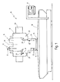
- Fig. 1 designates a machine tool as a whole.
- machine tool is in particular a to understand the so-called machining center, i.e. one numerically controlled machine tool, in particular drilling, milling and Filming to be carried out.
- Machining centers this Art either have a tool magazine in which a Many different tools stored in tool holders or a large number of tool changers, in which the tools between two set-up times in their Magazine position are kept permanent. Using an or these tools will be used in several such tool changers changed into a spindle of the machining center as required, thus a certain machining process under numerical Control can expire. After completion of the respective processing step the tool just used is unclamped and a new tool for the next machining process clamped. Machining centers of this type are general known.
- the machine tool 10 in FIG. 1 is a so-called traveling column machine.
- a traveling column 11 with a headstock 12 provided.
- the headstock 12 is on the traveling column 11 movable in particular in the vertical direction.
- the traveling column 11 is in the representation of FIG. 1 on a Base 15 movable perpendicular to the plane of the drawing.
- the base 15 is again in the illustration of FIG. 1 to the right and movable to the left on a fixed machine bed 16.
- the headstock 12 can thus be along three Cartesian coordinates.
- control panel 17 is provided for numerical Control of the machine tool 10 is used.
- the headstock 12 is to a central axis of symmetry 18th essentially symmetrical.
- the spindles 13, 14 are designed with vertical axes. Their axes are in Fig. 1 designated with 23 and 24 respectively.
- first one Gripping arm 25 of a first tool changer 27 In the vicinity of the first spindle 13 there is a first one Gripping arm 25 of a first tool changer 27 while a second gripper arm 29 of a second tool changer 30 itself is located near the second spindle 14.
- Gripping arms 25, 29 can be tools 31 or 32 of any kind be replaced in the spindles 13 and 14.
- each spindle 13, 14 is only one gripper arm 25 or 29 assigned.
- every spindle 13, 14 several alternating gripping arms can be assigned can each carry a tool 31, 32 and between a working position in which the tool is in the spindle 13, 14 is located, as well as a magazine position in which withdrawn from the spindle 13, 14 the tool 31, 32 ready for the next substitution.
- the special thing about machine tool 10 is that the second spindle 14 in a conventional manner for drilling and Milling work is designed while the first spindle 13 with is provided with a facing head, e.g. to the one to be processed Face turning certain surfaces or contours to be able to turn it off.
- the machine tool 12 can also be designed in this way be that only one spindle, namely the spindle 13, is provided is, which carries a facing or boring head, in the except Boring tools also "usual" tools such as drills, milling cutters etc. to be replaced, these tools in the boring head naturally have to be positioned centrally.
- the spindle rotor 50 is nearby its upper end rotatably connected to a pulley 51, via a belt 52 from a spindle drive 53 is drivable.
- the spindle rotor can be operated via a control line 54 50 are set in rotation.
- the lower end of the spindle rotor 50 runs in a rotationally symmetrical Flange 55 out.
- the flange 55 is used for attachment one designated overall by reference numeral 60 Facing head.
- Facing head 60 has a horizontally running rail 61 provided.
- a slide 62 runs on the rail 61
- Carriage 62 is with one acting in a vertical plane 45 ° toothing 63 provided.
- a counter toothing 64 Via a counter toothing 64, the Details can be explained below, one vertical movement (arrow 65) of the counter toothing in the manner of a Wedge gear in a horizontal movement (arrow 66) of the 45 ° toothing 63 are implemented.
- the 45 ° toothing 63 and the Counter toothing 64 thus form a gear for implementing one Vertical movement into a horizontal movement.
- the vertical drive movement serves to slide 62 on the facing head in the horizontal direction (arrow 66) move.
- the tool holder 67 is designed as an inner cone and is used for positive reception of a tool holder 68 on his upper end is designed as a standard hollow shaft cone, one has a complementary shape to the tool holder 67.
- the tool holder 68 enters here at its lower end Facing tool 69, although also a "usual" tool 31, 32 could be included. If now via the gear 63/64 a vertical drive movement in a horizontal movement of the Carriage 62 is implemented along the rail 61, so move the facing tool 69 in a horizontal plane, as indicated by 68 ', 69' in Fig. 2. The cutting edge of the facing tool 69, originally in axis 23 of the spindle 13 was located, moves on in the radial direction r of the axis 23 away. In this way known per se can thus the facing head 60 for turning surfaces with different Turning radius can be used.
- the tool holder 67 further comprises an expansion member 70, the in the open state to the upper end of the tool holder 68 approaching or insertable into this, while in the spread State the expansion member 70 the tool holder 68 form-fitting grips and in a vertical direction in the tool holder 67 can pull in and clamp there.
- the expansion member 70 is in the upper region with an external thread section 71 provided.
- the external thread section 71 runs in an internally threaded portion 72 of the tool holder 67, i.e. in the carriage 62.
- the threaded sections 71, 72 thus form one Spindle drive.
- the expansion member 70 runs into a driver 73, for example, a horizontal rib.
- driver 73 for example, a horizontal rib.
- driver 73 a counterpart 74 can be seen, which in shape the driver 73 is adapted.
- the counterpart 74 forms the lower end of a coupling rod 80.
- the coupling rod 80 is in the axis 23 of the spindle 13 arranged.
- the coupling rod 80 runs in one Piston 81 of a piston-cylinder unit 82.
- the unit 82 is provided with control lines 83, 84 to the piston 81 to be able to move in the vertical direction.
- the coupling rod 80 is one below its upper end Surround clutch 86, which in turn with a control line 87 is provided.
- the coupling 86 is arranged fixed in space and serves to lock the coupling rod 80 in a rotationally fixed manner if the control line 87 receives a corresponding signal is.
- the clutch 86 is designed as a ratchet clutch. This means that the clutch 86 up to an adjustable Torque limit holds and then releases, where the held part, namely the coupling rod 80, only up to turn to the next cover position of the ratchet elements can, for example by 180 °, until the coupling 86 is positive again sums up.
- a sensor is used to detect such a ratcheting process 88, which is arranged above the clutch 86. Over a Control line 89 can derive a control signal from sensor 88 become.
- a feed rod is used to actuate the counter toothing 64 90, which surrounds the coupling rod 80 as a tube.
- the feed rod 90 is in the upper end of the spindle rotor 50 held by radial bearings 91 in the radial direction.
- Axial bearing 92 is the feed rod 90 in a slide 93 held. This means that the delivery rod 90 is indeed rotate in the slide 93, but not in relation to the slide 93 can move axially.
- the carriage 93 is along a vertical axis 94 Rail 95 movable on the inside of the spindle housing 44 is formed.
- the carriage 93 is rigid with one at its top Ball screw 100 connected to the coupling rod 80 also surrounds loosely. On the ball screw 100 runs a spindle nut 101, which in turn in axial bearings 102 axially is held.
- the spindle nut 101 is rotatably fixed at its lower end a pulley 103 connected.
- the pulley 103 is again by means of a belt 104 from a feed drive 105 driven.
- a control line 106 is used for control of the feed drive 105.
- the spindle rotor By actuating the spindle drive 53, the spindle rotor is now 50 and thus the slide 62 and the tool holder 67 twisted. Since the expansion member 70 of the coupling rod 80 rotatably is held, the expansion member 70 moves through the the threaded portions 71, 72 formed spindle drive upwards and pulls the tool holder 68 into the tool holder 67.
- the clutch 86 is now released again and the coupling rod 80 move upwards by means of the piston-cylinder unit 82, so that the counterpart 74 again out of engagement with the driver 73 is.
- the facing tool 69 is now ready for use.
- the facing tool 69 is now in radial direction r shifted.
- the feed drive 105 controlled via the control line 106.
- the vertically fixed Spindle nut 101 is rotated via the belt drive 103, 104 and pulls the ball screw 100 up or down.
- the ball screw 100 takes over the slide 93 Delivery rod 90 in the vertical direction.
- the counter toothing 64 now runs on the 45 ° toothing 63 of the carriage 62, see above that this shifts in the horizontal direction (arrow 66), For example, in the dash-dotted position shown in Fig. 2 68 ', 69'.
- the facing task can be carried out in this position become.
- the limit torque preferably set higher in clutch 86 e.g. on 25 Nm because a higher torque is required to loosen.
- the tool changer 27 includes the gripper arm 25, which is conventional Is designed as a parallelogram linkage.
- Fig. 3 is a working position and dash-dotted lines a magazine position of the tool changer 27 is shown.
- the tool changer 27 is at its lower free end provided with a gripper 110.
- the gripper 110 grips one Gripping groove 114 on tool holder 68.
- clamping block 115 By means of one on the gripper 110 provided clamping block 115, which in the gripping groove 114 of the gripped tool holder 68, this can prevent vertical movement be secured.
- the clamp 115 is in the Gripping groove 114 continuously under the action of a coil spring 116 at.
- a lever 117 By means of a lever 117, the spring 116 depressed and the clamping block 115 lifted out of the gripping groove 114 become.
- the lever 117 can be operated servomechanically, but it is preferably designed as a hand lever.
- an actuation unit 120 attached, for example a pneumatic, hydraulic or electromagnetic actuator.
- the actuation unit 120 serves to actuate two claws 121, 122, which are symmetrical are held pivotably in axes 123, 124.
- the claws 121, 122 can be opened with it, as with arrows 125, 126 indicated, or they can be tight around the tool holder 68 be placed. Further details of the actuator unit such grippers 110 are e.g. described in EP 0 481 275 B1.
- the locking groove 130 is a locking stone 131 opposite that on the upper claw 121 in FIG. 4 of the gripper 110 is formed.
- the tool changer 27 is initially in that in FIG. 3 Magazine position shown in dash-dot lines.
- the gripper arm 25a in this case is pivoted obliquely upwards and outwards, so that the tool holder 68a outwards and upwards from the Facing head 60 is spaced.
- the Tool holder 68a can be manually loaded when a new episode to be prepared for machining operations.
- the user the machine tool actuates the lever 117 so that at opened claws 121, 122 a removal of the previously used Tool holder and a new one with the next one Machining task required tool holder 68a possible is.
- the tool holder 27 from the magazine position pivoted into the working position.
- the Tool holder 68 first the tool holder 67 from below offered, i.e. moved into a position in which the tool holder 68 still a slight vertical distance to Has tool holder 67.
- the tool holder 67 in the vertical direction relative to Tool changer 27 is movable, the tool holder 68 can be inserted from below into the tool holder 67.
- the gripper 110 can now in this position on the tool holder 68 remain, even if this is its processing task carries out. Alternatively, it is also possible to use the gripper 110 to move away from tool holder 68 in the horizontal direction, so that there is no longer any mechanical contact.
Description
Die Erfindung betrifft eine Werkzeugmaschine mit mindestens einer Spindel, der zumindest ein Werkzeugwechsler zum Einwechseln von Werkzeugen zugeordnet ist, wobei die Spindel mit einem Plandrehkopf bestückt ist, der Mittel zum numerisch gesteuerten Verstellen eines Plandrehwerkzeugs in einer Richtung senkrecht zur Achse der Spindel umfaßt, wobei der der Spindel zugeordnete Werkzeugwechsler einen Greifarm umfaßt, an dessen freiem Ende ein Greifer angeordnet ist, womit der Werkzeugwechsler zum Einwechseln von Werkzeugen in den Plandrehkopf ausgebildet ist.The invention relates to a machine tool with at least a spindle that has at least one tool changer for changing of tools is assigned, the spindle with a Facing head is equipped, the means for numerically controlled Adjusting a facing tool in one direction vertically to the axis of the spindle, the one assigned to the spindle Tool changer comprises a gripper arm, at its free end a gripper is arranged, with which the tool changer for Changing tools is formed in the facing head.
Eine Werkzeugmaschine der vorstehend genannten Art ist aus der FR A 2 564 012 A bekannt.A machine tool of the type mentioned above is from the FR A 2 564 012 A is known.
Eine weitere Werkzeugmaschine, die eine Spindel aufweist, der zumindest ein Werkzeugwechsler zum Einwechseln von Werkzeugen zugeordnet ist, ist aus der EP 0 360 168 B1 bekannt. Another machine tool that has a spindle that at least one tool changer for changing tools is known from EP 0 360 168 B1.
Bei der aus der EP 0 360 168 B1 bekannten Werkzeugmaschine handelt es sich um ein Verarbeitungszentrum, das als Mehrspindelmaschine ausgebildet ist. Dabei sind in völlig symmetrischer Bauweise zwei Spindeln nebeneinander angeordnet, denen jeweils ein Werkzeugwechsler zugeordnet ist. Die beiden Werkzeugwechsler umfassen jeweils zwei Paare von Greifarmen, von denen jeweils einer auf einer Seite der Spindel angeordnet ist. Die bekannte Werkzeugmaschine weist ein Werkzeugmagazin auf, das in der Draufsicht die Gestalt eines Hufeisens aufweist und in einer Horizontalebene angeordnet ist. Die beiden freien Enden des Hufeisens greifen seitlich um die Spindel herum. Sie sind am vorderen Ende mit einer Übergabeposition für Werkzeuge versehen. Die Werkzeuge werden in dem Hufeisenmagazin entlang einer Endlosbahn mittels einer Förderkette befördert. Durch die beiden Werkzeuggreifer mit jeweils zwei Greifarmen können nun Werkzeuge von den beiden Übergabepositionen, die sich seitlich und oberhalb der Werkzeugaufnahme der beiden Spindeln befinden, in die Werkzeugaufnahmen überführt werden.In the machine tool known from EP 0 360 168 B1 It is a processing center that works as a multi-spindle machine is trained. Doing so are completely symmetrical Construction two spindles arranged side by side, each of which a tool changer is assigned. The two tool changers each include two pairs of gripper arms, each of which one is arranged on one side of the spindle. The well-known Machine tool has a tool magazine, which in the Top view has the shape of a horseshoe and in one Horizontal plane is arranged. The two free ends of the Horseshoes grip around the side of the spindle. You are on Provide a transfer position for tools at the front end. The tools are placed along one in the horseshoe magazine Endless web conveyed by means of a conveyor chain. Through the two Tool grippers, each with two gripper arms, can now use tools from the two transfer positions, which are to the side and above the tool holder of the two spindles in which Tool holders are transferred.
Bei der bekannten Werkzeugmaschine liegen auf beiden Seiten, d.h. hinsichtlich beider Spindeln, vollkommen übereinstimmende Verhältnisse vor. Die Werkzeuge können daher in beliebiger Reihenfolge in beiden Spindeln eingesetzt werden.In the known machine tool lie on both sides, i.e. in terms of both spindles, completely identical Conditions before. The tools can therefore be used in any Sequence can be used in both spindles.
Es ist darüber hinaus bekannt, bei Bearbeitungszentren sogenannte Aus- oder Plandrehköpfe einzusetzen (siehe die eingangs genannte FR 2 564 012 A). Hierunter versteht man Anordnungen, mit denen es z.B. möglich ist, größere Oberflächen an Werkstücken planzudrehen. Die Besonderheit bei diesen Plandrehköpfen besteht dabei darin, daß ein Plandrehwerkzeug in radialer Richtung zur Spindelachse verstellt werden kann, so daß der Drehdurchmesser variabel ist. Auf diese Weise erhält man bei numerisch gesteuerten Bearbeitungszentren eine weitere numerische Achse. It is also known in so-called machining centers Inserting or facing heads to be used (see the aforementioned FR 2 564 012 A). This means arrangements with which it e.g. it is possible to turn larger surfaces on workpieces. The special feature of these facing heads is thereby in that a facing tool in the radial direction Spindle axis can be adjusted so that the turning diameter is variable. In this way you get with numerically controlled Machining centers another numerical axis.
Bei den bekannten Bearbeitungszentren mit Plandrehkopf wird z.B. der gesamte Plandrehkopf inklusive Plandrehwerkzeug montiert bzw. gegen einen kompletten neuen Plandrehkopf mit Plandrehwerkzeug ausgetauscht. Aufgrund des sehr hohen Gewichtes dieser Anordnungen geschieht dies regelmäßig durch manuelles Montieren. Der radiale Abstand der Schneide des Plandrehwerkzeugs von der Spindelachse wird dabei in der Regel ebenfalls manuell eingestellt.In the known machining centers with facing head e.g. the entire facing head including facing tool is installed or against a completely new facing head with facing tool exchanged. Because of the very high weight of this This is done regularly by manual assembly. The radial distance between the cutting edge of the facing tool and the The spindle axis is usually also set manually.
Andererseits ist es auch bekannt, den Plandrehkopf an der Spindel der Werkzeugmaschine zu belassen, und die Plandrehwerkzeuge von Hand auszutauschen. Der Plandrehkopf weist in diesem Falle eine Werkzeugaufnahme mit einem Spreizglied zum formschlüssigen Ergreifen und Spannen von die Werkzeuge haltenden Werkzeughaltern auf, wobei das Spreizglied mittels eines Spindeltriebes betätigbar ist. Dieser Spindeltrieb wird nun von Hand dadurch betätigt, daß durch die den Plandrehkopf tragende Spindel hindurch, die zu diesem Zweck als Hohlspindel ausgebildet ist, eine Art Schraubendreher hindurchgesteckt und das Spreizglied angezogen oder zur Freigabe des Werkzeughalters gelöst wird. Die Werkzeughalter werden dabei von Hand in die Werkzeugaufnahme des Plandrehkopfes eingesetzt bzw. aus dieser entnommen.On the other hand, it is also known, the facing head on the spindle the machine tool, and the facing tools exchanged by hand. The facing head points in this case a tool holder with a spreader for positive locking Gripping and clamping tool holders holding the tools on, the expansion member by means of a spindle drive can be actuated. This spindle drive is now done by hand actuates that through the spindle carrying the facing head through, which is designed for this purpose as a hollow spindle, a kind of screwdriver and the spreader tightened or released to release the tool holder. The tool holders are inserted into the tool holder by hand of the facing head inserted or removed from this.
Schließlich ist es weiter bekannt, eine Werkzeugmaschine mit einer ganzen Reihe von Werkzeugwechslern zu versehen, von denen z.B. zwölf Stück im Kreis um die Spindel herum angeordnet sind. Jeder Werkzeugwechsler weist eine Magazinstellung auf, in der er von der Spindel zurückgezogen ist und das von seinem Greifer getragene Werkzeug in sicherer Entfernung zu der Spindel hält. Diese Greifer sind nun wahlweise unter die Spindel bringbar, wo das Werkzeug durch geeignete Maßnahmen in die Spindel eingekoppelt werden kann. Während der Bearbeitung des Werkstückes verbleibt der Greifer an dem Werkzeug, so daß der Werkzeugwechsel hier sehr schnell erfolgen kann. Nach erfolgtem Bearbeitungsgang wird nämlich der Werkzeugwechsler mit dem auszuwechselnden Werkzeug von der Spindel zurückgezogen, während der Werkzeugwechsler mit dem einzuwechselnden Werkzeug gleichzeitig der Werkzeugaufnahme in der Spindel zugeführt wird. Dadurch, daß der Greifer während der Bearbeitung an dem Werkzeug verbleibt, entfallen zusätzliche Bewegungen des Werkzeugwechslers.Finally, it is also known to use a machine tool a wide range of tool changers, of which e.g. twelve pieces are arranged in a circle around the spindle. Each tool changer has a magazine position in which he has withdrawn from the spindle and that of his gripper tool held at a safe distance from the spindle. These grippers can now be placed under the spindle, where the tool by appropriate measures in the spindle can be coupled. During the machining of the workpiece the gripper remains on the tool so that the tool change can be done very quickly here. After the processing step namely the tool changer with the one to be replaced Tool withdrawn from the spindle while the tool changer with the tool to be changed at the same time Tool holder is fed into the spindle. As a result of that the gripper remains on the tool during machining, there are no additional movements of the tool changer.
Der Erfindung liegt demgegenüber die Aufgabe zugrunde, eine Werkzeugmaschine der eingangs genannten Art dahingehend weiterzubilden, daß die Spindel zwar Plandrehaufgaben ausführen kann, dies jedoch unter eigenständiger numerischer Kontrolle sämtlicher Parameter und bei erleichtertem Wechsel und hoher Stellungsgenauigkeit des Plandrehwerkzeugs während des Einwechselns.The invention is based on the object, a To further develop machine tools of the type mentioned at the beginning that the spindle can carry out facing tasks however, this all under independent numerical control Parameters and with easier change and high positional accuracy of the facing tool during insertion.
Diese Aufgabe wird erfindungsgemäß bei der eingangs erwähnten Werkzeugmaschine dadurch gelöst, daß der Greifer einen Werkzeughalter formschlüssig umfaßt, daß dem Greifer erste Rastmittel zum Verrasten des Werkzeughalters in Achsrichtung sowie zweite Rastmittel zum Verrasten des Werkzeughalters in Umfangsrichtung zugeordnet sind, und daß die Rastmittel separat betätigbar sind.This object is inventively mentioned in the opening paragraph Machine tool solved in that the gripper has a tool holder form-fitting that the gripper first locking means for locking the tool holder in the axial direction and second Locking means for locking the tool holder in the circumferential direction are assigned, and that the locking means can be actuated separately.
Die der Erfindung zugrundeliegende Aufgabe wird auf diese Weise vollkommen gelöst.The object on which the invention is based is achieved in this way completely solved.
Bei der erfindungsgemäßen Werkzeugmaschine ist nämlich die Spindel fest mit dem Plandrehkopf versehen, während das Auswechseln der Plandrehwerkzeuge über einen üblichen Werkzeugwechsler abläuft. Auf diese Weise wird bereits die Variabilität der Anordnung deutlich vergrößert, weil ebenso wie bei herkömmlichen Werkzeugwechslern auch bei dem Plandrehkopf ein schnelles Auswechseln unterschiedlicher Plandrehwerkzeuge möglich ist. Ferner hat das feste Anbringen des Plandrehkopfs an der Spindel den Vorteil, daß auch die radiale Verstellung des Plandrehwerkzeugs intern ausgeführt werden kann, insbesondere über eine numerisch steuerbare Zusatzachse. Auf diese Weise wird daher der Gesamtvorgang noch umfassender automatisiert. Selbstverständlich kann auch ein übliches Werkzeug, wie z.B. ein Fräser oder Bohrer, in den Plandrehkopf eingewechselt werden, wobei dieser dann eine mittige oder zentrierte Stellung zu der Spindel einnehmen muß, so daß auch Bohr- und Fräsarbeiten mit der neuen Werkzeugmaschine durchgeführt werden können. Auf diese Weise wird für einen breiten Anwendungsbereich der neuen Werkzeugmaschine gesorgt. Selbstverständlich kann es auch möglich sein, die Werkzeugmaschine mit einer zweiten Spindel auszurüsten, der eigene Werkzeugwechsler zugeordnet sind, so daß der Plandrehkopf lediglich Plandrehwerkzeuge aufnimmt, während die zweite Spindel für andere Werkzeuge vorgesehen ist.In the machine tool according to the invention, namely Provide the spindle with the facing head while changing of the facing tools using a conventional tool changer expires. This way the variability is already there the arrangement significantly enlarged, because just like with conventional Tool changers are also quick with the facing head It is possible to change different facing tools. Furthermore, the fixed attachment of the facing head to the Spindle the advantage that the radial adjustment of the facing tool can be executed internally, especially via a numerically controllable additional axis. That way therefore the entire process is automated even more comprehensively. Of course can also be a common tool such as a router or drill, are inserted into the facing head, whereby this then a central or centered position to the spindle must take, so that drilling and milling work with the new Machine tool can be carried out. In this way is used for a wide range of applications of the new machine tool worried. Of course it can also be possible equip the machine tool with a second spindle, the own tool changer are assigned so that the facing head only face facing tools while the second Spindle is provided for other tools.
An dem freien Ende des Greifarmes ist dabei der Greifer angeordnet, der den Werkzeughalter formschlüssig umfaßt. Diese Maßnahme hat den Vorteil, daß das Werkzeug mit definierter Schneidenstellung in die Spindel des Plandrehkopfes einsetzbar ist.The gripper is arranged on the free end of the gripper arm, which includes the tool holder in a form-fitting manner. This Measure has the advantage that the tool with a defined Cutting position can be used in the spindle of the facing head is.
Ferner dienen die verschiedenen Rastmittel dazu, um diese definierte Stellung des Werkzeugs auch während des Überführens von der Magazinstellung in die Arbeitsstellung aufrechtzuerhalten. Schließlich kann je nach Einsatzfall der Greifer während des Arbeitens des Plandrehwerkzeugs an diesem verbleiben oder von diesem entfernt werden. Wenn das Plandrehwerkzeug jedoch radial verfahren werden muß, wird der Greifer vorher zurückgezogen. Dies ist wegen der erfindungsgemäß vorgesehenen Rastmittel auch möglich. Furthermore, the various locking means serve to this defined position of the tool even during transfer from the magazine position to the working position. Finally, depending on the application, the gripper remain on the facing tool while it is working or be removed from it. If the facing tool however must be moved radially, the gripper is withdrawn beforehand. This is because of those provided according to the invention Locking means also possible.
Bei einer bevorzugten Weiterbildung dieses Ausführungsbeispiels sind in einer Arbeitsstellung, in der der Werkzeughalter in einer Werkzeugaufnahme des Plandrehkopfes eingespannt ist, die ersten Rastmittel verrastet und die zweiten Rastmittel nicht verrastet.In a preferred development of this embodiment are in a working position in which the tool holder is in a tool holder of the facing head is clamped, the locked first locking means and not the second locking means locked.
Diese Maßnahme hat den Vorteil, daß das Werkzeug bis zum Ende des Einspannvorganges hin in vertikaler Richtung gesichert ist, wobei die insoweit vorliegende Verrastung auch während des Arbeitens des Werkzeuges aufrechterhalten werden kann, wie bereits erwähnt. Die zweiten Rastmittel sind hingegen nicht mehr verrastet, weil bei eingespanntem Werkzeug die Umfangsrichtung des Werkzeuges definiert ist und dieses ansonsten nicht gedreht werden könnte.This measure has the advantage that the tool to the end the clamping process is secured in the vertical direction, the existing latching also during the Working of the tool can be maintained as already mentioned. The second locking means, however, are not more locked because the circumferential direction when the tool is clamped of the tool is defined and otherwise not could be rotated.
Besonders bevorzugt ist, wenn in einer Magazinstellung, in der der Werkzeughalter sich im Abstand von einer Werkzeugaufnahme des Plandrehkopfes befindet, die ersten Rastmittel manuell entrastbar sind.It is particularly preferred if in a magazine position in which the tool holder is at a distance from a tool holder of the facing head, the first locking means manually are releasable.
Diese Maßnahme hat den Vorteil, daß der Bestückungsvorgang in der Magazinstellung erleichtert wird. Dies gilt insbesondere dann, wenn die Werkzeugmaschine mehrere Werkzeugwechselvorrichtungen aufweist, die auch in ihrer Magazinstellung das Werkzeug in ihrem Greifer halten, wie dies eingangs im Zusammenhang mit einer bekannten Werkzeugmaschine bereits erörtert wurde.This measure has the advantage that the assembly process in the magazine position is facilitated. This is especially true then when the machine tool has multiple tool changing devices has the tool in its magazine position hold in their gripper as related in the beginning a known machine tool has already been discussed.
Eine gute Wirkung wird dabei dann erzielt, wenn die ersten Rastmittel unter Federkraft in Eingriff stehen.A good effect is achieved when the first The locking means engage under spring force.
Diese Maßnahme hat den Vorteil, daß die erste Verrastung in technisch sehr einfacher Weise permanent aufrechterhalten werden kann. This measure has the advantage that the first latching in technically very easy to maintain permanently can.
Bei weiteren Ausführungsbeispielen der Erfindung umfassen die Mittel zum Verstellen des Plandrehwerkzeugs ein Getriebe, das eine in Richtung der Achse der Spindel wirkende Kraft in eine in der Richtung senkrecht zur Achse wirkende Betätigungskraft zum Verstellen des Plandrehwerkzeugs umsetzt.In further embodiments of the invention, the Means for adjusting the facing tool a gear, the a force acting in the direction of the axis of the spindle into a operating force acting in the direction perpendicular to the axis to adjust the facing tool.
Diese Maßnahme hat den Vorteil, daß in einem Spindelstock, dessen Elemente in vertikaler Richtung organisiert sind, eine leichte Verstellung des Plandrehwerkzeugs möglich wird.This measure has the advantage that in a headstock Elements organized in the vertical direction are easy Adjustment of the facing tool is possible.
Dies gilt insbesondere dann, wenn das Getriebe eine 45°-Verzahnung mit Gegenverzahnung umfaßt.This is especially true if the gearbox has 45 ° teeth with counter teeth.
Diese Maßnahme hat nämlich den Vorteil, daß eine Vertikalbewegung in äußerst einfacher Weise in eine Horizontalbewegung umgesetzt wird.This measure has the advantage that a vertical movement converted into a horizontal movement in an extremely simple manner becomes.
Bei einer bevorzugten Weiterbildung des Ausführungsbeispiels wird die in Richtung der Achse wirkende Kraft mittels einer Zustellstange erzeugt, wobei die Zustellstange über einen Spindeltrieb in Richtung der Achse verschiebbar ist.In a preferred development of the exemplary embodiment is the force acting in the direction of the axis by means of a Delivery rod generated, the delivery rod over a Spindle drive is displaceable in the direction of the axis.
Diese Maßnahme hat den Vorteil, daß über einen motorischen Drehantrieb in einfacher Weise eine Vertikalbewegung der Zustellstange erzeugt wird, die wiederum in die Radialbewegung des Plandrehwerkzeuges umgesetzt wird.This measure has the advantage that a motor Rotary drive in a simple manner a vertical movement of the Delivery rod is generated, which in turn in the radial movement of the facing tool is implemented.
Bei weiteren Ausführungsbeispielen der Erfindung, bei denen der Plandrehkopf eine Werkzeugaufnahme mit einem Spreizglied zum formschlüssigen Ergreifen und Spannen des Werkzeughalters umfaßt, ist das Spreizglied durch Drehen der Spindel zum Spannen und/oder Lösen des Werkzeughalters betätigbar. In further embodiments of the invention, in which the facing head is a tool holder with an expansion link for positive gripping and clamping of the tool holder includes, the expansion member by turning the spindle for clamping and / or release of the tool holder can be actuated.
Diese Maßnahme hat den Vorteil, daß die Spannmittel im Plandrehkopf völlig autonom arbeiten, so daß die Werkzeugaufnahme beliebig in Radialrichtung verschiebbar ist, ohne daß die Spannkraft der Spannmittel unterbrochen wird. Dies ist bei herkömmlichen Spannmechanismen nicht möglich, bei denen kontinuierlich eine Zugkraft auf die Spannmittel ausgeübt wird, die üblicherweise über die gesamte Länge des Spindelstocks erzeugt und aufrechterhalten wird. Dadurch, daß jetzt durch einfaches Drehen der den Plandrehkopf haltenden Spindel der Werkzeughalter gespannt/gelöst werden kann, kann auf einen weiteren Antrieb zum automatischen Lösen/Spannen des Werkzeughalters verzichtet werden. Die beim Stand der Technik von Hand vorgenommenen Maßnahmen des Lösens und Spannens des Werkzeughalters werden somit ebenfalls auf sehr einfache und vorteilhafte Weise automatisiert, ohne daß zusätzliche konstruktive Maßnahmen erforderlich sind, um die gattungsbildende Werkzeugmaschine umzukonstruieren.This measure has the advantage that the clamping device in the facing head work completely autonomously, so that the tool holder is freely displaceable in the radial direction without the Clamping force of the clamping device is interrupted. This is at conventional clamping mechanisms are not possible, in which continuous a tensile force is exerted on the clamping means usually generated over the entire length of the headstock and is maintained. Because now by simple Turn the tool holder spindle holding the facing head can be tensioned / released, on another drive dispensed with for automatic loosening / clamping of the tool holder become. Those made by hand in the prior art Measures of loosening and clamping the tool holder will be thus also in a very simple and advantageous manner automated without additional constructive measures are required to use the generic machine tool to reconstruct.
Dabei ist es bevorzugt, wenn dem Spreizglied ein Spindeltrieb zugeordnet ist, der durch Verdrehen der drehfest mit der Spindel verbundenen Werkzeugaufnahme betätigt wird.It is preferred if the expansion member has a spindle drive is assigned by rotating the spindle with the spindle connected tool holder is actuated.
Diese Maßnahme ist konstruktiv von Vorteil, weil die zum Spannen/Lösen des Werkzeughalters erforderliche Vertikalbewegung des Spreizgliedes durch den Spindeltrieb aus der über die Werkzeugaufnahme von der Spindel übermittelte Drehung abgeleitet werden kann.This measure is structurally advantageous because the Clamping / loosening of the tool holder required vertical movement of the expansion member through the spindle drive from the over Tool holder derived from the rotation transmitted by the spindle can be.
Bei einer Weiterbildung dieses Ausführungsbeispiels wird der Spindeltrieb durch einen Außengewindeabschnitt am Spreizglied sowie einen Innengewindeabschnitt an der Werkzeugaufnahme gebildet. In a further development of this embodiment, the Spindle drive through an external thread section on the expansion element and an internal thread section on the tool holder educated.
Diese Maßnahme hat den Vorteil, daß der Spindeltrieb zum Einspannen des Werkzeugs in besonders einfacher Weise realisiert werden kann.This measure has the advantage that the spindle drive The tool is clamped in a particularly simple manner can be.
In Weiterbildung dieses Ausführungsbeispiels weist das Spreizglied einen Mitnehmer auf, über den der Außengewindeabschnitt im Innengewindeabschnitt verdrehbar ist. Der Mitnehmer ist dabei vorzugsweise mittels einer Kuppelstange verdrehbar, die an einem Ende mit einem zum Mitnehmer komplementären Gegenstück versehen ist. Der Plandrehkopf ist dabei insbesondere derart verstellbar, daß der Mitnehmer und das Gegenstück in eine miteinander fluchtende Stellung bringbar sind, wobei in bevorzugter Weise das Spreizglied drehfest fixierbar ist, derart, daß der Spindeltrieb durch Verdrehen der Werkzeugaufnahme betätigt wird.In a further development of this exemplary embodiment, the expansion member has a driver over which the male thread section is rotatable in the internal thread section. The driver is there preferably rotatable by means of a coupling rod, which on a Provide the end with a counterpart complementary to the driver is. The facing head is particularly adjustable such that that the driver and the counterpart in one with each other aligned position can be brought, preferably the expansion member can be fixed in a rotationally fixed manner, such that the spindle drive is actuated by turning the tool holder.
Diese Maßnahmen haben den Vorteil, daß in der fluchtenden Stellung das Spreizglied über die Kuppelstange vom anderen Ende des Spindelstocks her betätigbar ist, wobei "betätigbar" vorzugsweise so zu verstehen ist, daß das Spreizglied festgehalten wird, während die eigentliche Anzugsbewegung des Spindeltriebs durch ein Anfahren des Spindelrotors erreicht wird.These measures have the advantage that in the aligned Position the spreader over the coupling rod from the other end of the headstock can be actuated, wherein "actuatable" is preferably to be understood so that the expansion member is held during the actual tightening movement of the spindle drive is achieved by starting the spindle rotor.
Weitere Vorteile ergeben sich aus der Beschreibung und der beigefügten Zeichnung. Es versteht sich, daß die vorstehend genannten und die nachstehend noch zu erläuternden Merkmale nicht nur in der jeweils angegebenen Kombination, sondern auch in anderen Kombinationen oder in Alleinstellung verwendbar sind, ohne den Rahmen der vorliegenden Erfindung zu verlassen.Further advantages result from the description and the attached drawing. It is understood that the above mentioned and the features to be explained below not only in the specified combination, but also can be used in other combinations or on their own, without departing from the scope of the present invention.
Ausführungsbeispiele der Erfindung sind in der Zeichnung dargestellt und werden in der nachfolgenden Beschreibung näher erläutert. Es zeigen:
- Fig. 1
- eine äußerst schematisierte Vorderansicht auf ein Ausführungsbeispiel einer erfindungsgemäßen Werkzeugmaschine;
- Fig. 2
- in vergrößertem Maßstab eine Querschnittsdarstellung entlang der Linie II-II von Fig. 1;
- Fig. 3
- eine noch weiter vergrößerte Detailansicht zur Erläuterung eines Werkzeugwechslers, wie er an der Werkzeugmaschine gemäß Fig. 1 und 2 Verwendung finden kann;
- Fig. 4
- in noch weiter vergrößertem Maßstab eine Draufsicht auf einen Greifer in einem Werkzeugwechsler gemäß Fig. 3.
- Fig. 1
- an extremely schematic front view of an embodiment of a machine tool according to the invention;
- Fig. 2
- on a larger scale a cross-sectional view along the line II-II of Fig. 1;
- Fig. 3
- a further enlarged detail view for explaining a tool changer, as it can be used on the machine tool according to Figures 1 and 2.
- Fig. 4
- A plan view of a gripper in a tool changer according to FIG. 3 on an even larger scale.
In Fig. 1 bezeichnet 10 insgesamt eine Werkzeugmaschine. Unter "Werkzeugmaschine" ist im vorliegenden Fall insbesondere ein sogenanntes Bearbeitungszentrum zu verstehen, d.h. eine numerisch gesteuerte Werkzeugmaschine, in der insbesondere Bohr-, Fräs-und Dreharbeiten ausgeführt werden. Bearbeitungszentren dieser Art verfügen entweder über ein Werkzeugmagazin, in dem eine Vielzahl unterschiedlicher Werkzeuge in Werkzeughaltern gespeichert sind, oder über eine große Zahl von Werkzeugwechslern, in denen die Werkzeuge zwischen zwei Rüstzeiten in deren Magazinstellung permanent gehalten sind. Mittels eines oder mehrerer solcher Werkzeugwechsler werden diese Werkzeuge je nach Bedarf in eine Spindel des Bearbeitungszentrums eingewechselt, damit ein bestimmter Bearbeitungsvorgang unter numerischer Kontrolle ablaufen kann. Nach Beendigung des jeweiligen Bearbeitungsschrittes wird das soeben benutzte Werkzeug ausgespannt und ein neues Werkzeug für den nächsten Bearbeitungsvorgang eingespannt. Bearbeitungszentren dieser Art sind allgemein bekannt. In Fig. 1, 10 designates a machine tool as a whole. Under In the present case, "machine tool" is in particular a to understand the so-called machining center, i.e. one numerically controlled machine tool, in particular drilling, milling and Filming to be carried out. Machining centers this Art either have a tool magazine in which a Many different tools stored in tool holders or a large number of tool changers, in which the tools between two set-up times in their Magazine position are kept permanent. Using an or these tools will be used in several such tool changers changed into a spindle of the machining center as required, thus a certain machining process under numerical Control can expire. After completion of the respective processing step the tool just used is unclamped and a new tool for the next machining process clamped. Machining centers of this type are general known.
Die Werkzeugmaschine 10 in Fig. 1 ist eine sogenannte Fahrständermaschine.
Dabei ist ein Fahrständer 11 mit einem Spindelstock
12 versehen. Der Spindelstock 12 ist am Fahrständer 11
insbesondere in Vertikalrichtung verfahrbar.The
Bei der in Fig. 1 dargestellten Werkzeugmaschine 10 ist der
Spindelstock 12 mit zwei Spindeln, nämlich einer ersten Spindel
13 und einer zweiten Spindel 14, ausgerüstet.In the
Der Fahrständer 11 ist in der Darstellung der Fig. 1 auf einem
Sockel 15 senkrecht zur Zeichenebene verfahrbar. Der Sockel
15 ist wiederum in der Darstellung der Fig. 1 nach rechts und
nach links auf einem raumfesten Maschinenbett 16 verfahrbar.
Insgesamt kann der Spindelstock 12 damit entlang von drei
kartesischen Koordinaten verfahren werden.The traveling
Zur Steuerung des Bewegungsablaufs und des gesamten Bearbeitungsvorganges
ist ein Steuerpult 17 vorgesehen, das zur numerischen
Steuerung der Werkzeugmaschine 10 dient.To control the sequence of movements and the entire machining process
a
Der Spindelstock 12 ist zu einer mittleren Symmetrieachse 18
im wesentlichen symmetrisch ausgebildet. Die Spindeln 13, 14
sind vertikalachsig ausgebildet. Ihre Achsen sind in Fig. 1
mit 23 bzw. 24 bezeichnet.The
In der Nähe der ersten Spindel 13 befindet sich ein erster
Greifarm 25 eines ersten Werkzeugwechslers 27, während ein
zweiter Greifarm 29 eines zweiten Werkzeugwechslers 30 sich
in der Nähe der zweiten Spindel 14 befindet. Mittels der
Greifarme 25, 29 können Werkzeuge 31 bzw. 32 beliebiger Art
in die Spindeln 13 bzw. 14 eingewechselt werden. In der Darstellung
der Fig. 1 ist jeder Spindel 13, 14 jeweils nur ein Greifarm
25 bzw. 29 zugeordnet. Es versteht sich jedoch, daß jeder Spindel
13, 14 mehrere abwechselnd wirkende Greifarme zugeordnet werden
können, die jeweils ein Werkzeug 31, 32 tragen und zwischen
einer Arbeitsstellung, in der sich das Werkzeug in der Spindel
13, 14 befindet, sowie einer Magazinstellung wechseln, in der
sie von der Spindel 13, 14 zurückgezogen das Werkzeug 31, 32
für das nächste Einwechseln bereithalten.In the vicinity of the
Das Besondere bei der Werkzeugmaschine 10 besteht darin, daß
die zweite Spindel 14 in herkömmlicher Weise für Bohr- und
Fräsarbeiten ausgelegt ist, während die erste Spindel 13 mit
einem Plandrehkopf versehen ist, um z.B. an den zu bearbeitenden
Werkstücken bestimmte Oberflächen plandrehen oder Konturen
ausdrehen zu können.The special thing about
Selbstverständlich kann die Werkzeugmaschine 12 auch so ausgelegt
sein, daß nur eine Spindel, nämlich die Spindel 13, vorgesehen
ist, die einen Plan- oder Ausdrehkopf trägt, in den außer
Ausdrehwerkzeugen auch "übliche" Werkzeuge wie Bohrer, Fräser
etc. eingewechselt werden, wobei diese Werkzeuge im Ausdrehkopf
natürlich zentrisch positioniert werden müssen.Of course, the
In der vergrößerten Querschnittsdarstellung gemäß Fig. 2 sind
weitere Einzelheiten der ersten Spindel 13 zu erkennen.2 are in the enlarged cross-sectional view
to recognize further details of the
Man erkennt zunächst, daß am Fahrständer 11 eine vertikale
Schiene 41 angeordnet ist, auf der entlang einer vertikalen
Achse 42 ein Schlitten 43 verfahrbar ist. Der Schlitten 43 trägt
ein Spindelgehäuse 44. Die hierzu vorgesehenen Antriebs- und
Steuereinheiten sind an sich bekannt und in Fig. 2 der Übersichtlichkeit
halber nicht dargestellt.It can first be seen that on the traveling
Am unteren Ende des Spindelgehäuses 44 sind in einer zentralen
Aufnahme derselben Lager 49 angebracht, die zur Lagerung eines
Spindelrotors 50 dienen. Der Spindelrotor 50 ist in der Nähe
seines oberen Endes drehfest mit einer Riemenscheibe 51 verbunden,
die über einen Riemen 52 von einem Spindelantrieb 53
antreibbar ist. Über eine Steuerleitung 54 kann der Spindelrotor
50 damit in Drehung versetzt werden.At the lower end of the
Das untere Ende des Spindelrotors 50 läuft in einen rotationssymmetrischen
Flansch 55 aus. Der Flansch 55 dient zur Befestigung
eines insgesamt mit dem Bezugszeichen 60 bezeichneten
Plandrehkopfs.The lower end of the
Der Plandrehkopf 60 ist mit einer horizontal verlaufenden Schiene
61 versehen. Auf der Schiene 61 läuft ein Schlitten 62. Der
Schlitten 62 ist mit einer in einer Vertikalebene wirkenden
45°-Verzahnung 63 versehen. Über eine Gegenverzahnung 64, deren
Einzelheiten weiter unten noch erläutert werden, kann eine
vertikale Bewegung (Pfeil 65) der Gegenverzahnung nach Art eines
Keilgetriebes in eine horizontale Bewegung (Pfeil 66) der 45°-Verzahnung
63 umgesetzt werden. Die 45°-Verzahnung 63 und die
Gegenverzahnung 64 bilden somit ein Getriebe zur Umsetzung einer
Vertikalbewegung in eine Horizontalbewegung.Facing
Die vertikale Antriebsbewegung dient dazu, den Schlitten 62 auf dem Plandrehkopf in horizontaler Richtung (Pfeil 66) zu verschieben.The vertical drive movement serves to slide 62 on the facing head in the horizontal direction (arrow 66) move.
Am unteren Ende des Schlittens 62 ist eine Werkzeugaufnahme
67 von an sich herkömmlicher Bauart angeordnet. Die Werkzeugaufnahme
67 ist als Innenkegel ausgebildet und dient zur
formschlüssigen Aufnahme eines Werkzeughalters 68, der an seinem
oberen Ende als Norm-Hohlschaftkegel ausgebildet ist, der eine
komplementäre Form zur Werkzeugaufnahme 67 aufweist. At the lower end of the
Der Werkzeughalter 68 trägt an seinem unteren Ende hier ein
Plandrehwerkzeug 69, obwohl auch ein "übliches" Werkzeug 31,
32 aufgenommen sein könnte. Wenn nun über das Getriebe 63/64
eine vertikale Antriebsbewegung in eine Horizontalbewegung des
Schlittens 62 entlang der Schiene 61 umgesetzt wird, so wird
das Plandrehwerkzeug 69 in einer Horizontalebene verfahren,
wie mit 68', 69' in Fig. 2 angedeutet. Die Schneide des Plandrehwerkzeugs
69, die sich ursprünglich in der Achse 23 der Spindel
13 befand, bewegt sich auf diese in radialer Richtung r von
der Achse 23 weg. Auf diese an sich bekannte Weise kann somit
der Plandrehkopf 60 zum Abdrehen von Flächen mit unterschiedlichem
Drehradius eingesetzt werden.The
Die Werkzeugaufnahme 67 umfaßt ferner ein Spreizglied 70, das
im ungespreizten Zustand an das obere Ende des Werkzeughalters
68 heran oder in dieses einführbar ist, während im gespreizten
Zustand das Spreizglied 70 den Werkzeughalter 68 formschlüssig
ergreift und in einer vertikalen Richtung in die Werkzeugaufnahme
67 hineinzuziehen und dort einzuspannen vermag.The
Das Spreizglied 70 ist im oberen Bereich mit einem Außengewindeabschnitt
71 versehen. Der Außengewindeabschnitt 71 läuft in
einem Innengewindeabschnitt 72 der Werkzeugaufnahme 67, d.h.
im Schlitten 62. Die Gewindeabschnitte 71, 72 bilden somit einen
Spindeltrieb.The
Am oberen Ende läuft das Spreizglied 70 in einen Mitnehmer 73,
bspw. eine horizontale Rippe, aus. Oberhalb des Mitnehmers 73
ist ein Gegenstück 74 zu erkennen, das in der Formgebung an
den Mitnehmer 73 angepaßt ist. At the upper end, the
Das Gegenstück 74 bildet das untere Ende einer Kuppelstange
80. Die Kuppelstange 80 ist in der Achse 23 der Spindel 13
angeordnet. Am oberen Ende läuft die Kuppelstange 80 in einem
Kolben 81 einer Kolben-Zylinder-Einheit 82 aus. Die Einheit
82 ist mit Steuerleitungen 83, 84 versehen, um den Kolben 81
in vertikaler Richtung verfahren zu können.The
Auf diese Weise ist es möglich, das Gegenstück 74 entweder vom
Mitnehmer 73 abzuheben, wie in Fig. 2 dargestellt ist, oder
das Gegenstück 74 mit dem Mitnehmer 73 in Eingriff zu bringen.In this way it is possible to either
Die Kuppelstange 80 ist unterhalb ihres oberen Endes von einer
Kupplung 86 umgeben, die ihrerseits mit einer Steuerleitung
87 versehen ist. Die Kupplung 86 ist raumfest angeordnet und
dient dazu, die Kuppelstange 80 drehfest zu arretieren, wenn
die Steuerleitung 87 mit einem entsprechenden Signal beaufschlagt
ist.The
Die Kupplung 86 ist als Ratschkupplung ausgebildet. Dies
bedeutet, daß die Kupplung 86 bis zu einem einstellbaren
Grenzwert des einwirkenden Drehmoments hält und dann löst, wobei
das gehaltene Teil, nämlich die Kuppelstange 80, sich nur bis
in die nächste Deckungsstellung der Ratschelemente verdrehen
kann, bspw. um 180°, bis die Kupplung 86 erneut formschlüssig
faßt.The clutch 86 is designed as a ratchet clutch. This
means that the clutch 86 up to an adjustable
Torque limit holds and then releases, where
the held part, namely the
Zur Detektion eines solchen Ratschvorganges dient ein Sensor
88, der oberhalb der Kupplung 86 angeordnet ist. Über eine
Steuerleitung 89 kann vom Sensor 88 ein Steuersignal abgeleitet
werden.A sensor is used to detect such a
Zur Betätigung der Gegenverzahnung 64 dient eine Zustellstange
90, die als Rohr die Kuppelstange 80 umgibt. A feed rod is used to actuate the
Am unteren Ende läuft die Zustellstange 90 in die bereits
erwähnte Gegenverzahnung 64 aus, die in Fig. 2 der Übersichtlichkeit
halber nicht im einzelnen dargestellt ist.At the lower end, the
Die Zustellstange 90 ist im oberen Ende des Spindelrotors 50
mittels Radiallagern 91 in radialer Richtung gehalten. Über
Axiallager 92 ist die Zustellstange 90 in einem Schlitten 93
gehalten. Dies bedeutet, daß die Zustellstange 90 sich zwar
im Schlitten 93 drehen, aber nicht gegenüber dem Schlitten 93
axial verschieben kann.The
Der Schlitten 93 ist entlang einer vertikalen Achse 94 an einer
Schiene 95 verfahrbar, die auf der Innenseite des Spindelgehäuses
44 ausgebildet ist.The
Der Schlitten 93 ist an seiner Oberseite starr mit einer
Kugelgewindespindel 100 verbunden, die die Kuppelstange 80
ebenfalls lose umgibt. Auf der Kugelgewindespindel 100 läuft
eine Spindelmutter 101, die ihrerseits in Axiallagern 102 axial
festgehalten wird.The
Die Spindelmutter 101 ist an ihrem unteren Ende drehfest mit
einer Riemenscheibe 103 verbunden. Die Riemenscheibe 103 wird
wiederum mittels eines Riemens 104 von einem Zustellantrieb
105 angetrieben. Eine Steuerleitung 106 dient zur Steuerung
des Zustellantriebes 105.The
Die Wirkungsweise der Anordnung gemäß Fig. 2 ist wie folgt:The mode of operation of the arrangement according to FIG. 2 is as follows:
Wenn der Werkzeughalter 68 von unten in die Werkzeugaufnahme
67 eingeführt wird, welcher Vorgang weiter unten anhand der
Fig. 3 und 4 noch näher beschrieben werden wird, gelangt das
Spreizglied 70 in Eingriff mit dem Werkzeughalter 68. Durch
Betätigen der Kolben-Zylinder-Einheit 82 wird nun die Kuppelstange
80 aus der in Fig. 2 eingezeichneten Stellung nach unten
verfahren, und zwar soweit, daß das Gegenstück 74 den Mitnehmer
73 ergreift. Sobald dies geschehen ist, wird die Kupplung 86
über die Steuerleitung 87 geschlossen, wobei ein Grenzwert des
Haltemomentes in der Kupplung 86 von bspw. 15 Nm eingestellt
wird.If the
Durch Betätigen des Spindelantriebes 53 wird nun der Spindelrotor
50 und damit der Schlitten 62 und die Werkzeugaufnahme 67
verdreht. Da das Spreizglied 70 von der Kuppelstange 80 drehfest
gehalten wird, bewegt sich das Spreizglied 70 über den durch
die Gewindeabschnitte 71, 72 gebildeten Spindeltrieb nach oben
und zieht den Werkzeughalter 68 in die Werkzeugaufnahme 67 ein.By actuating the
Sobald das voreingestellte Drehmoment von z.B. 15 Nm erreicht
ist, rastet die Ratschkupplung 86 aus. Dieser Ratschvorgang
wird über den Sensor 88 erkannt und über die Steuerleitung 89
dem Steuerpult 17 mitgeteilt, worauf der Spindelantrieb 53
gestoppt wird.As soon as the preset torque of e.g. Reached 15 Nm
ratchet clutch 86 disengages. This ratcheting process
is recognized via the
Die Kupplung 86 wird nun wieder gelöst und die Kuppelstange
80 mittels der Kolben-Zylinder-Einheit 82 nach oben verfahren,
so daß das Gegenstück 74 wieder außer Eingriff mit dem Mitnehmer
73 ist.The clutch 86 is now released again and the
Das Plandrehwerkzeug 69 ist nun einsatzbereit. Je nach vorliegender
Plandrehaufgabe wird das Plandrehwerkzeug 69 nun in
radialer Richtung r verschoben. Hierzu wird der Zustellantrieb
105 über die Steuerleitung 106 angesteuert. Die vertikal feste
Spindelmutter 101 wird über den Riementrieb 103, 104 verdreht
und zieht die Kugelgewindespindel 100 nach oben oder nach unten.
Die Kugelgewindespindel 100 nimmt über den Schlitten 93 die
Zustellstange 90 in vertikaler Richtung mit. Die Gegenverzahnung
64 läuft nun auf der 45°-Verzahnung 63 des Schlittens 62, so
daß dieser sich in Horizontalrichtung (Pfeil 66) verschiebt,
bspw. in die in Fig. 2 eingezeichnete strichpunktierte Stellung
68', 69'. In dieser Stellung kann die Plandrehaufgabe ausgeführt
werden.The facing
Für einen nachfolgenden Werkzeugwechsel muß zunächst der
Schlitten 62 auf der Schiene 61 wieder in eine Stellung verfahren
werden, in der die Achse des Spreizgliedes 70 mit der Spindelachse
23 und damit der Kuppelstange 80 fluchtet. Dann können
sich die vorstehend beschriebenen Vorgänge anschließen. Zum
Ausspannen des Werkzeughalters 68 wird das Grenz-Drehmoment
in der Kupplung 86 vorzugsweise höher eingestellt, z.B. auf
25 Nm, weil zum Lösen ein höheres Drehmoment erforderlich ist.For a subsequent tool change, the
Move the
Wichtig dabei ist, daß der Plandrehkopf 60 erfindungsgemäß am
Flansch 55 des Spindelrotors 50 verbleibt und nur die Plandrehwerkzeuge
69 ausgetauscht werden.It is important that the facing
In den Fig. 3 und 4 sind nähere Einzelheiten des zugehörigen
Werkzeugwechslers 27 dargestellt.3 and 4 are further details of the associated
Der Werkzeugwechsler 27 umfaßt den Greifarm 25, der in herkömmlicher
Weise als Parallelogrammgestänge ausgebildet ist.
In Fig. 3 ist durchgezogen eine Arbeitsstellung und strichpunktiert
eine Magazinstellung des Werkzeugwechslers 27 dargestellt.The
Der Werkzeugwechsler 27 ist an seinem unteren freien Ende mit
einem Greifer 110 versehen. Der Greifer 110 ergreift eine
Greifnut 114 am Werkzeughalter 68. Mittels eines am Greifer
110 vorgesehenen Klemmsteins 115, der in die Greifnut 114 des
erfaßten Werkzeughalters 68 greift, kann dieser gegen Vertikalbewegung
gesichert werden. Der Klemmstein 115 liegt in der
Greifnut 114 kontinuierlich unter der Wirkung einer Schraubenfeder
116 an. Mittels eines Hebels 117 kann die Feder 116
überdrückt und der Klemmstein 115 aus der Greifnut 114 abgehoben
werden. Der Hebel 117 kann servomechanisch betätigt werden,
vorzugsweise ist er aber als Handhebel ausgebildet.The
Am rückwärtigen Ende des Greifers 110 ist eine Betätigungseinheit
120 angebracht, bspw. eine pneumatische, hydraulische oder
elektromagnetische Betätigungseinheit. Die Betätigungseinheit
120 dient zum Betätigen zweier Klauen 121, 122, die symmetrisch
in Achsen 123, 124 schwenkbar gehalten sind. Die Klauen 121,
122 können damit geöffnet werden, wie mit Pfeilen 125, 126
angedeutet, oder sie können dicht um den Werkzeughalter 68 herum
gelegt werden. Weitere Einzelheiten der Betätigungseinheit eines
solchen Greifers 110 sind z.B. in der EP 0 481 275 B1 beschrieben.At the rear end of the
An dem in Fig. 1 oberen Umfang des Werkzeughalters 68 ist eine
Rastnut 130 erkennbar. Der Rastnut 130 steht ein Raststein 131
gegenüber, der an der in Fig. 4 oberen Klaue 121 des Greifers
110 ausgebildet ist.On the upper circumference of the
Die Wirkungsweise des in den Fig. 3 und 4 dargestellten Werkzeugwechslers 27 ist wie folgt:The operation of the tool changer shown in FIGS. 3 and 4 27 is as follows:
Der Werkzeugwechsler 27 befindet sich zunächst in der in Fig. 3
strichpunktiert eingezeichneten Magazinstellung. Der Greifarm
25a ist in diesem Fall schräg nach oben und außen verschwenkt,
so daß der Werkzeughalter 68a nach außen und nach oben vom
Plandrehkopf 60 beabstandet ist. In dieser Stellung kann der
Werkzeughalter 68a manuell bestückt werden, wenn eine neue Folge
von Bearbeitungsvorgängen vorbereitet werden soll. Der Benutzer
der Werkzeugmaschine betätigt dazu den Hebel 117, so daß bei
geöffneten Klauen 121, 122 eine Entnahme des zuvor benutzten
Werkzeughalters und eine Neubestückung mit dem für die nächste
Bearbeitungsaufgabe erforderlichen Werkzeughalter 68a möglich
ist.The
Wenn im numerischen Steuerprogramm nun das betreffende Werkzeug
aufgerufen wird, so wird der Werkzeughalter 27 aus der Magazinstellung
in die Arbeitsstellung verschwenkt. Dabei wird der
Werkzeughalter 68 zunächst der Werkzeugaufnahme 67 von unten
angeboten, d.h. in eine Stellung gefahren, in der der Werkzeughalter
68 noch einen geringfügigen vertikalen Abstand zur
Werkzeugaufnahme 67 hat.If the tool in question in the numerical control program
is called, the
Da die Anordnung in an sich bekannter Weise so getroffen ist,
daß die Werkzeugaufnahme 67 in Vertikalrichtung relativ zum
Werkzeugwechsler 27 verfahrbar ist, kann der Werkzeughalter
68 von unten in die Werkzeugaufnahme 67 eingefahren werden.Since the arrangement is made in a manner known per se,
that the
Während des bisher geschilderten Bewegungsablaufs ist es wichtig,
daß der Werkzeughalter 68 in einer vorbestimmten Umfangsstellung
gehalten wird. Dies wird dadurch bewirkt, daß bei geschlossenen
Klauen 121, 122 der Raststein 131 in die Rastnut 130 greift,
so daß der Werkzeughalter 68 in Umfangsrichtung fixiert ist.
Diese Umfangs-Bezugsposition wird damit bereits während des
Bestückens des Greifers 110 festgelegt. Zusätzlich ist der
Werkzeughalter 68, wie erwähnt, in vertikaler Richtung mittels
des Klemmsteins 115 fixiert, der in die Greifnut 114 eingreift.During the movement sequence described so far, it is important
that the
Wenn nun der Werkzeughalter von unten in den Bereich der
Werkzeugaufnahme 67 herangefahren wird, so gelangen formschlüssige
Mitnahmeelemente, bspw. ein Nutenstein am Spindelrotor
50 und eine Nut in der oberen Radialfläche des Werkzeughalters
68 (jeweils nicht dargestellt), miteinander in Eingriff. Die
definierte Umfangsstellung ist damit weiter gewährleistet. Die
Klauen 121, 122 können dann mittels der Betätigungseinheit 120
geöffnet werden, wie in Fig. 4 dargestellt. Der Werkzeughalter
68 ist damit frei drehbar, aber in Vertikalrichtung immer noch
fixiert, wofür das Zusammenspiel zwischen Werkzeugaufnahme
67/Hohlschaftkegel und Klemmstein 115/Greifnut 114 sorgt.Now if the tool holder from below into the area of
Nachdem sich der Werkzeughalter 68 in dieser Stellung befindet,
beginnt der oben im Zusammenhang mit der Figur 2 bereits
beschriebene Einkuppelvorgang, in dem nach dem Arretieren der
Kuppelstange 80 der Spindelrotor 50 über die Spindel 13 die
Werkzeugaufnahme 67 dreht, um das Spreizglied 70 anzuziehen.
Da der Werkzeughalter 68 zu diesem Zeitpunkt bereits drehfest
mit der Werkzeugaufnahme 67 gekuppelt ist, dreht sich die
Werkzeugaufnahme 68 während dieses Spannvorganges mit, weshalb
zuvor die Klauen 121, 122 geöffnet werden mußten.After the
Der Greifer 110 kann nun in dieser Stellung am Werkzeughalter
68 verbleiben, auch wenn dieser seine Bearbeitungsaufgabe
durchführt. Alternativ ist es aber auch möglich, den Greifer
110 in Horizontalrichtung vom Werkzeughalter 68 weg zu fahren,
so daß kein mechanischer Kontakt mehr vorhanden ist.The
Claims (13)
- A machine tool comprising at least one spindle (13) with which is associated at least one tool changer (27) for exchanging tools (31, 69), wherein said spindle (13) is fitted with a facing head (60) having means for numerically controlled displacement of a facing tool (69) in a direction (r) perpendicular to an axis (23) of said spindle (13), and wherein said tool changer (27) associated with said spindle (13) comprises a gripper arm (25) having a gripper (110) arranged at its free end, whereby said tool changer (27) is designed for exchanging tools (31, 69) at said facing head, characterized in that said gripper (110) positively encloses a tool holder (68), first snap means (114, 115) for snap-locking said tool holder (68) in the axial direction and second snap means (130, 131) for snap-locking said tool holder (68) in the circumferential direction are associated with said gripper (110), and said snap means (114, 115/130, 131) are separately actuatable.
- The machine tool of claim 1, characterized in that in a working position in which the tool holder (68) is clamped into a tool receptacle (67) of the facing head (68), said first snap means (114, 115) are snap-locked and said second snap means (130, 131) are not snap-locked.
- The machine tool of claim 1 or claim 2, characterized in that in a magazine position in which the tool holder (68) is located at a distance from a tool receptacle (67) of said facing head (60) said first snap means (114, 115) can be manually unlocked.
- The machine tool of any or several of claims 1 - 3, characterized in that said first snap means (114, 115) are mutually engaged under spring force (116).
- The machine tool of any or several of claims 1 - 4, characterized in that said means for displacement of said facing tool (69) comprise a drive train that converts a force acting in the direction of the axis (23) of the spindle (13) into an actuation force acting in the direction (r) perpendicular to the axis (23), for displacement of the facing tool (69).
- The machine tool of claim 5, characterized in that the drive train comprises a 45° tooth set (63) with a mating tooth set (64).
- The machine tool of claim 5 or claim 6, characterized in that the force acting in the direction of the axis (23) is generated by means of an adjusting rod (90), the adjusting rod (90) being displaceable in the direction of the axis (23) by means of a spindle drive (100, 101).
- The machine tool of any or several of claims 1 - 7, wherein said facing head (60) comprises a tool receptacle (69) with a spreading member (70) for positive gripping and clamping of the tool holder (68), characterized in that the spreading member (70) is actuatable by rotating said spindle (13) to clamp and/or release said tool holder (68).
- The machine tool of claim 8, characterized in that a spindle drive (71, 72) actuated by rotation of the tool receptacle (67) that is joined nonrotatably to the spindle (13), is associated with the spreading member (70).
- The machine tool of claim 9, characterized in that the spindle drive is comprised of an externally threaded section (71) on the spreading member (70) and an internally threaded section (72) on the tool receptacle (67).
- The machine tool of claim 10, characterized in that the spreading member (70) has a catch (73) by means of which the externally threaded section (71) can be rotated in the internally threaded section (72).
- The machine tool of claim 11, characterized in that the catch (73) is rotatable by means of a coupling rod (80) that is equipped at one end with a mating element (74) complementary to the catch (73), and can be immobilized nonrotatably.
- The machine tool of any or several of claims 8 - 12, characterized in that the spreading member (70) can be immobilized nonrotatably.
Applications Claiming Priority (4)
| Application Number | Priority Date | Filing Date | Title |
|---|---|---|---|
| DE19532399 | 1995-09-02 | ||
| DE19532399 | 1995-09-02 | ||
| DE19537071A DE19537071C2 (en) | 1995-09-02 | 1995-10-05 | Machine tool equipped with a facing head |
| DE19537071 | 1995-10-05 |
Publications (2)
| Publication Number | Publication Date |
|---|---|
| EP0761384A1 EP0761384A1 (en) | 1997-03-12 |
| EP0761384B1 true EP0761384B1 (en) | 2000-04-12 |
Family
ID=26018237
Family Applications (1)
| Application Number | Title | Priority Date | Filing Date |
|---|---|---|---|
| EP96111071A Expired - Lifetime EP0761384B1 (en) | 1995-09-02 | 1996-07-10 | Machine tool |
Country Status (4)
| Country | Link |
|---|---|
| US (1) | US5772566A (en) |
| EP (1) | EP0761384B1 (en) |
| JP (1) | JPH09108977A (en) |
| ES (1) | ES2145350T3 (en) |
Families Citing this family (12)
| Publication number | Priority date | Publication date | Assignee | Title |
|---|---|---|---|---|
| DE10323592B4 (en) | 2003-05-16 | 2006-03-23 | Chiron-Werke Gmbh & Co Kg | machine tool |
| DE19716491C2 (en) * | 1997-04-19 | 1999-07-29 | Chiron Werke Gmbh | Machine tool for machining workpiece cavities |
| US6416450B2 (en) * | 1999-07-28 | 2002-07-09 | Thermwood Corporation | Machine tool with improved tool changer means |
| US6350222B2 (en) * | 1999-07-28 | 2002-02-26 | Thermwood Corporation | Machine tool with improved tool changer means |
| US6440066B1 (en) * | 1999-11-16 | 2002-08-27 | Cardiac Intelligence Corporation | Automated collection and analysis patient care system and method for ordering and prioritizing multiple health disorders to identify an index disorder |
| US20030169460A1 (en) * | 2002-03-11 | 2003-09-11 | Siemens Technology-To-Business Center, Llc | On-demand service performance upgrade for wireless network |
| GB0207298D0 (en) * | 2002-03-28 | 2002-05-08 | Renishaw Plc | Apparatus for changing operating modules on a coordinate positioning machine |
| DE10323593A1 (en) | 2003-05-16 | 2004-12-09 | Chiron-Werke Gmbh & Co Kg | machine tool |
| DE20311973U1 (en) * | 2003-07-31 | 2003-10-02 | Dienes Werke | Slitting machine set up for an automatic knife change |
| DE102004029045B4 (en) * | 2004-06-14 | 2006-12-07 | Chiron-Werke Gmbh & Co. Kg | Carrier for tool holders |
| JP2006281390A (en) * | 2005-04-01 | 2006-10-19 | Jtekt Corp | Combined machine tool, and method for machining workpiece using the same |
| TWI780661B (en) * | 2021-04-14 | 2022-10-11 | 寅翊智造股份有限公司 | Spindle structure of machine tool |
Family Cites Families (15)
| Publication number | Priority date | Publication date | Assignee | Title |
|---|---|---|---|---|
| DE1777295B2 (en) * | 1966-07-13 | 1974-07-25 | Gebr. Heller Maschinenfabrik Gmbh, 7440 Nuertingen | Machine tool with automatic tool change. Eliminated from: 1552324 |
| DE1777296C3 (en) * | 1966-07-13 | 1975-02-20 | Gebr. Heller Maschinenfabrik Gmbh, 7440 Nuertingen | Machine tool with automatic tool change |
| GB1194173A (en) * | 1966-07-13 | 1970-06-10 | Heller Maschinenfabrik G M B H | Machine Tool with Automatic Tool Changing. |
| GB1343363A (en) * | 1971-03-31 | 1974-01-10 | Innocenti Soc Generale | Machine tools |
| DE2230144C3 (en) * | 1972-06-21 | 1980-03-27 | Schiess Ag, 4000 Duesseldorf | Tool support with a chisel slide that can be moved vertically therein with a tool changer assigned to the chisel slide |
| DE2728975C2 (en) * | 1977-06-28 | 1981-10-08 | Komet Stahlhalter- Und Werkzeugfabrik Robert Breuning Gmbh, 7122 Besigheim | Face and boring head |
| US4354305A (en) * | 1978-12-21 | 1982-10-19 | Giddings & Lewis, Inc. | Contouring and threading attachment for multi-function machine tools |
| FR2462100A1 (en) * | 1979-07-31 | 1981-02-13 | Renault | MACHINE TOOL WITH AUTOMATIC TOOL CHANGE |
| US4329770A (en) * | 1980-05-01 | 1982-05-18 | Kearney & Trecker Corporation | Automatic tool changer |
| IT1134870B (en) * | 1980-12-23 | 1986-08-20 | Andrea Spa D | HEAD FOR BORING AND FACING, AS WELL AS MACHINE TOOL SUITED TO RECEIVE THIS HEAD |
| US4467517A (en) * | 1981-04-13 | 1984-08-28 | Mitsubishi Jukogyo Kabushiki Kaisha | Tool changer for facing head |
| FR2564012B1 (en) * | 1984-05-11 | 1986-10-10 | Renault | BORING-DRESSING TRAY, PARTICULARLY FOR MACHINING ASSEMBLY WITH INTERCHANGEABLE HEADS |
| FR2568802B1 (en) * | 1984-08-07 | 1986-09-12 | Renault | MULTI-SPINDLE HEAD FOR A MACHINE TOOL, PARTICULARLY FOR A MACHINING ASSEMBLY WITH INTERCHANGEABLE HEADS |
| DE3831869A1 (en) * | 1988-09-20 | 1990-03-29 | Chiron Werke Gmbh | MACHINE TOOL |
| JPH04201147A (en) * | 1990-11-30 | 1992-07-22 | Ariyoshi Kiko Shiyuudan:Kk | Automatic tool change mechanism for machine tool |
-
1996
- 1996-07-10 ES ES96111071T patent/ES2145350T3/en not_active Expired - Lifetime
- 1996-07-10 EP EP96111071A patent/EP0761384B1/en not_active Expired - Lifetime
- 1996-08-13 JP JP8229451A patent/JPH09108977A/en active Pending
- 1996-08-26 US US08/702,921 patent/US5772566A/en not_active Expired - Fee Related
Also Published As
| Publication number | Publication date |
|---|---|
| EP0761384A1 (en) | 1997-03-12 |
| JPH09108977A (en) | 1997-04-28 |
| ES2145350T3 (en) | 2000-07-01 |
| US5772566A (en) | 1998-06-30 |
Similar Documents
| Publication | Publication Date | Title |
|---|---|---|
| WO1993007981A1 (en) | Lathe | |
| EP0761384B1 (en) | Machine tool | |
| DE1777019B2 (en) | Machine tool with a tool changing device | |
| DE4320019A1 (en) | Machine tool with automatic tool changer and tool holder - has tool chuck on tool holder and tool transfer mechanism to preset tool change position | |
| DE3506901C2 (en) | ||
| EP0791427A1 (en) | Gripper for workpieces | |
| DE19919434A1 (en) | Part transfer facility | |
| DE2818018C2 (en) | ||
| DE102010044781A1 (en) | Processing machine with drive shaft | |
| EP0761383A2 (en) | Machine tool | |
| DE3010934C2 (en) | ||
| DE2143780A1 (en) | Tool changing device for machine tools | |
| DE3519754C2 (en) | ||
| EP0342257B1 (en) | Machine tool with magazine and tool changer | |
| EP1289711B1 (en) | Device for gripping and transporting workpieces in turning machines | |
| EP0425994A2 (en) | Method and machine for cutting off tubes and at the same time chamferring the formed tube ends | |
| WO2000003835A1 (en) | Machine tool with tool changing device | |
| DE19537071C2 (en) | Machine tool equipped with a facing head | |
| DE19537070C2 (en) | Machine tool with a tool changing device | |
| DE19936502C1 (en) | Arrangement for pivotable workpiece delivery into machine tool working region has drive spindle connected to holder for fixing drive element with attached rotatable workpiece holders | |
| DE3315661C2 (en) | Chuck for a hammer drilling tool | |
| DE102018121554A1 (en) | Facing knob and tool change procedure | |
| DE3246994A1 (en) | Process and apparatus for automatically adjusting a lathe tool with bit carrier | |
| EP0175672B1 (en) | Device for handling work pieces | |
| DE2919873C2 (en) | Device for independent tool change in hobbing machines |
Legal Events
| Date | Code | Title | Description |
|---|---|---|---|
| PUAI | Public reference made under article 153(3) epc to a published international application that has entered the european phase |
Free format text: ORIGINAL CODE: 0009012 |
|
| AK | Designated contracting states |
Kind code of ref document: A1 Designated state(s): DE ES FR GB IT |
|
| 17P | Request for examination filed |
Effective date: 19970523 |
|
| 17Q | First examination report despatched |
Effective date: 19971113 |
|
| GRAG | Despatch of communication of intention to grant |
Free format text: ORIGINAL CODE: EPIDOS AGRA |
|
| GRAG | Despatch of communication of intention to grant |
Free format text: ORIGINAL CODE: EPIDOS AGRA |
|
| GRAH | Despatch of communication of intention to grant a patent |
Free format text: ORIGINAL CODE: EPIDOS IGRA |
|
| GRAH | Despatch of communication of intention to grant a patent |
Free format text: ORIGINAL CODE: EPIDOS IGRA |
|
| GRAA | (expected) grant |
Free format text: ORIGINAL CODE: 0009210 |
|
| AK | Designated contracting states |
Kind code of ref document: B1 Designated state(s): DE ES FR GB IT |
|
| PGFP | Annual fee paid to national office [announced via postgrant information from national office to epo] |
Ref country code: FR Payment date: 20000516 Year of fee payment: 5 |
|
| REF | Corresponds to: |
Ref document number: 59604942 Country of ref document: DE Date of ref document: 20000518 |
|
| PGFP | Annual fee paid to national office [announced via postgrant information from national office to epo] |
Ref country code: GB Payment date: 20000614 Year of fee payment: 5 |
|
| ITF | It: translation for a ep patent filed |
Owner name: LUPPI & CRUGNOLA |
|
| ET | Fr: translation filed | ||
| REG | Reference to a national code |
Ref country code: ES Ref legal event code: FG2A Ref document number: 2145350 Country of ref document: ES Kind code of ref document: T3 |
|
| PGFP | Annual fee paid to national office [announced via postgrant information from national office to epo] |
Ref country code: ES Payment date: 20000720 Year of fee payment: 5 |
|
| GBT | Gb: translation of ep patent filed (gb section 77(6)(a)/1977) |
Effective date: 20000711 |
|
| PGFP | Annual fee paid to national office [announced via postgrant information from national office to epo] |
Ref country code: DE Payment date: 20000824 Year of fee payment: 5 |
|
| PLBE | No opposition filed within time limit |
Free format text: ORIGINAL CODE: 0009261 |
|
| STAA | Information on the status of an ep patent application or granted ep patent |
Free format text: STATUS: NO OPPOSITION FILED WITHIN TIME LIMIT |
|
| 26N | No opposition filed | ||
| PG25 | Lapsed in a contracting state [announced via postgrant information from national office to epo] |
Ref country code: GB Free format text: LAPSE BECAUSE OF NON-PAYMENT OF DUE FEES Effective date: 20010710 |
|
| PG25 | Lapsed in a contracting state [announced via postgrant information from national office to epo] |
Ref country code: ES Free format text: LAPSE BECAUSE OF NON-PAYMENT OF DUE FEES Effective date: 20010711 |
|
| GBPC | Gb: european patent ceased through non-payment of renewal fee |
Effective date: 20010710 |
|
| PG25 | Lapsed in a contracting state [announced via postgrant information from national office to epo] |
Ref country code: FR Free format text: LAPSE BECAUSE OF NON-PAYMENT OF DUE FEES Effective date: 20020329 |
|
| PG25 | Lapsed in a contracting state [announced via postgrant information from national office to epo] |
Ref country code: DE Free format text: LAPSE BECAUSE OF NON-PAYMENT OF DUE FEES Effective date: 20020501 |
|
| REG | Reference to a national code |
Ref country code: FR Ref legal event code: ST |
|
| REG | Reference to a national code |
Ref country code: ES Ref legal event code: FD2A Effective date: 20020810 |
|
| PG25 | Lapsed in a contracting state [announced via postgrant information from national office to epo] |
Ref country code: IT Free format text: LAPSE BECAUSE OF NON-PAYMENT OF DUE FEES;WARNING: LAPSES OF ITALIAN PATENTS WITH EFFECTIVE DATE BEFORE 2007 MAY HAVE OCCURRED AT ANY TIME BEFORE 2007. THE CORRECT EFFECTIVE DATE MAY BE DIFFERENT FROM THE ONE RECORDED. Effective date: 20050710 |