EP0761342B1 - Molding apparatus and method - Google Patents
Molding apparatus and method Download PDFInfo
- Publication number
- EP0761342B1 EP0761342B1 EP96114410A EP96114410A EP0761342B1 EP 0761342 B1 EP0761342 B1 EP 0761342B1 EP 96114410 A EP96114410 A EP 96114410A EP 96114410 A EP96114410 A EP 96114410A EP 0761342 B1 EP0761342 B1 EP 0761342B1
- Authority
- EP
- European Patent Office
- Prior art keywords
- space
- molding sand
- mold
- passage means
- mold space
- Prior art date
- Legal status (The legal status is an assumption and is not a legal conclusion. Google has not performed a legal analysis and makes no representation as to the accuracy of the status listed.)
- Expired - Lifetime
Links
- 238000000034 method Methods 0.000 title claims description 7
- 238000000465 moulding Methods 0.000 title description 10
- 239000003110 molding sand Substances 0.000 claims description 52
- 230000000630 rising effect Effects 0.000 claims description 3
- 239000003570 air Substances 0.000 description 25
- 239000012080 ambient air Substances 0.000 description 7
- 239000011230 binding agent Substances 0.000 description 2
- 239000004576 sand Substances 0.000 description 2
- 239000003795 chemical substances by application Substances 0.000 description 1
- 238000004519 manufacturing process Methods 0.000 description 1
- 238000003756 stirring Methods 0.000 description 1
Images




Classifications
-
- B—PERFORMING OPERATIONS; TRANSPORTING
- B22—CASTING; POWDER METALLURGY
- B22C—FOUNDRY MOULDING
- B22C15/00—Moulding machines characterised by the compacting mechanism; Accessories therefor
-
- B—PERFORMING OPERATIONS; TRANSPORTING
- B22—CASTING; POWDER METALLURGY
- B22D—CASTING OF METALS; CASTING OF OTHER SUBSTANCES BY THE SAME PROCESSES OR DEVICES
- B22D45/00—Equipment for casting, not otherwise provided for
Definitions
- This invention relates to an apparatus and a method for producing a mold (including a core) by means of air pressure, in particular, for producing a mold in a mold space in a pattern box.
- vent plugs are provided in such parts to create a vacuum in them.
- a pattern box provided with vent plugs has a high cost and takes a lot of work.
- This invention is conceived to resolve these disadvantages. Its purpose is to provide a molding apparatus and a method that can fill the narrow or upwardly-extending parts of a mold space, and that can fill a complicated mold space.
- This invention is based on a finding that if molding sand is charged part by part into a mold space of a pattern box, and each part is subject to air pressure, the pattern box is sufficiently filled with the molding sand.
- the air may be pressurized air, or ambient air that flows into a mold space wherein there is a vacuum.
- a predetermined amount of molding sand that fills the mold space of a pattern box is divided into two parts. A first part of the molding sand is charged into the mold space. Then an air flow at a set speed is introduced into the mold space. Then the second part of the molding sand is charged into the mold space, and an air flow at a set speed is again introduced into the mold space.
- Fig. 1 is a cross-sectional view of a first embodiment of the molding apparatus of the present invention.
- Fig. 2 is a cross-sectional view of a second embodiment of the molding apparatus of the present invention.
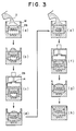
- Fig. 3 shows the method of the invention carried out by the apparatus of Fig. 2.
- Fig. 4 is a cross-sectional front view of a third embodiment of the molding apparatus of the present invention.
- Fig. 5 is a cross-sectional side view of the apparatus of Fig. 4.
- Fig. 1 shows a first embodiment of a molding apparatus of the invention.
- An upper hopper 1 has a belt feeder 3 that acts as means to meter and feed molding sand 2.
- a first feeding amount and a second feeding amount of the molding sand are preset.
- the pipe 6 is connected to a pattern box 8 so that the pipe communicates with the mold space 7 of the pattern box 8.
- the mold space 7 includes an upright space 7A and a horizontal space 7B extending transversely of the upright space 7A.
- the port 4 has a gate 5, which closes the pipe 6.
- the pattern box 8 is placed on a table 9, which moves vertically.
- An air-suction pipe 10 is connected to the feeding pipe 6.
- a vacuum pump 12 is connected to the air-suction pipe 10 through an air-suction valve 11.
- An air-supply pipe 13 is also connected to the feeding pipe 6.
- the air-supply pipe 13 is connected to a compressed air-supply tank 15 via an air-introducing valve 14.
- all the molding sand 2 that is necessary to produce a mold is divided into at least two portions, to preset the first and second feeding amounts of the molding sand.
- the molding sand may be divided into two to three portions, and for a large one, it may be divided into three to ten portions. Further, for a complicated mold, the number of the divided portions of the molding sand is increased in comparison with the number for a simple one.
- the gate 5 is opened, and the first amount of the molding sand metered by the belt feeder 3 drops through the port 4 into the mold space 7.
- the air-introducing valve 14 is closed when the molding sand is fed.
- the gate 5 is then closed. Under these conditions the assembly of the pipe 6 and pattern box 8 is sealingly closed.
- the air-suction valve 11 is opened, and a vacuum in the mold space 7 is created by the vacuum pump 12. When the air pressure of the mold space 7 reaches a vacuum between 2 to 100 torr, the air-suction valve 11 is closed.
- the air-introducing valve 14 is opened so that a first compressed-air flow is introduced from the tank 15 at a pressure-rising rate of 3 to 60 MPa/sec (30 to 600 kg/cm 2 /sec).
- two or three compressed air flows are introduced into the mold space 7.
- the molding sand in the mold space is subjected to the air flow or flows.
- the gate 5 is again opened.
- the second amount of the molding sand is fed into the mold space by the belt feeder 3, and the gate 5 is closed. Then the air in the pattern box 8 is removed by the pump 12, and in the same way a compressed-air flow or flows are introduced into the mold space 7. These steps are repeated until the final amount of the divided molding sand is fed into the mold space. Thus the space is filled with molding sand, and the mold or core is produced. After this, the table 9 is lowered, and the mold is taken out.
- the compressed-air tank 15 may be eliminated, and ambient air flows may be introduced into the mold space instead of compressed-air flows.
- self-curing molding sand is used.
- gas-cured molding sand may be used.
- a gas generator 16 is connected to the pattern box 8 so that curing gas communicates with the mold space. The curing gas is introduced into the mold space through a plate 17 after the final air flow is introduced into the mold space.
- a vacuum is created in the mold space 7 before the second amount of the molding sand is fed, this vacuum may not be necessary, and some air flows may be introduced into the mold space after the air-introducing valve 14 is opened.
- the pressure-rising rate of air flows is preferably 3 to 60 MPa/sec, and a rate of 10 to 40 MPa/sec is more preferable. If the rate is more than 40 MPa/sec, the air-introducing valve must be large, and thus it is not economical.
- the range of the vacuum of the mold space is preferably between 2.67 hPa to 133 hPa (2 to 100 torr), and within this range the highest vacuum is more preferable.
- the pressure of the compressed air is preferably 0.2 to 0.9 MPa, and a range of 0.4 to 0.9 MPa is more preferable. Within this range the highest vacuum is best if air of such pressure is available.
- Fig. 2 shows a second embodiment of the molding apparatus of the present invention.
- the apparatus has a column 21.
- a roller conveyor 22 is mounted on a horizontally-extending part of the column 21.
- a cover 29 is mounted on an arm 28E, which is in turn slidably mounted on a vertical guide bar 25 secured to the vertically-extending part of the column 21.
- the arm 28E is vertically moved along the guide bar by an actuator 23 so that the cover 29 is pressed against a filling frame M attached to the top of the pattern box 28.
- the cover 29 has an intermediate floor 29A, which has a central opening 29D.
- a cylinder 30 is mounted on the arm 28E.
- the cylinder 30 has an air-introducing valve 14. This valve covers the central opening to close a space 29C defined by the cover 29, filling frame M, and pattern box 28.
- An air passage 29B, which communicates with ambient air, is formed in the cover such that the space 29C communicates with ambient air when the valve 14 is opened.
- gas-cured molding sand 2 is introduced into the pattern box 28 and cured.
- a minimum number of vent holes and vent plugs are provided in the pattern box.
- the filling frame M is placed on the halves of the pattern box, and as in Fig. 3(b) a part of the molding sand is fed into the filling frame.
- the molding sand fed into the box is leveled, and then as in Fig. 3(c) the space is closed by the cover.
- valve 11 is opened to create a vacuum in the closed space of 2.67 hPa to 133 hPa (2 to 100 torr).
- the valve 11 is then closed, while the valve 14 is opened so that the ambient air flow enters the passage 29B, opening 29D, and space 29C at the air-pressure rising rate of 5 to 60 MPa/sec (50 to 600 kg/cm 2 /sec) (preferably, at the rate of 20 to 40 MPa/sec ((200 to 400 kg/cm 2 /sec).
- an amount of molding sand is introduced into the mold space in the pattern box 28 as in Fig. 3(d).
- the pattern box and filling frame are moved to a gas-curing station (not shown), and the molding sand in them is gas-cured there.
- Figs. 4 and 5 show a third embodiment of the molding apparatus of the present invention.
- the apparatus includes a frame F on which are mounted, from top to bottom, a sand-container 38, mixer assembly 34, molding-sand feeder means 31, pressure-reducing means 32, ambient-air-introducing means 33, and pattern-box-transfer means 35.
- the mixer assembly 34 which is disposed under the sand-container 38, includes upper and lower mixers 34a, 34a and a binder-supplying device (not shown).
- the vane 34b of each mixer rotates, mixes, and advances the sand.
- a sand-feeding hopper 31a is disposed under the output end of the lower mixer 34a.
- the hopper 31a and a sand-introducing gate 31b disposed under the hopper constitute a sand-feeding means 31.
- the gate 31b is opened, a predetermined amount of mixed molding sand is fed into a mold space 39 in a pattern box 42.
- the mold space 7 of the pattern box 28 includes an upright space 7A, a horizontal space 7B extending transversely of the upright space 7A, and a vertical space 7C extending upwardly or downwardly from the horizontal space 7B.
- the pressure-reducing means 32 which includes a hollow container V, is disposed under the sand-feeding means 31. At one end the hollow container V communicates with the opening of the pattern box 42. At the other end it communicates with a vacuum pump 12 through an air-suction valve 11 and a filter 32c. A vacuum is created in the mold space 39 to a range between 2 to 100 torr.
- air-introducing means 33 is integrally mounted on the hollow container V. This means has an air-introducing valve 33a through which ambient air is introduced into the mold space 39 (see Fig. 4).
- the pattern box 42 is horizontally transferred by a conveyor 36, and is raised to a predetermined level by a cylinder 36.
- the hollow container is lowered and its lower port V sealingly pressed against the opening of the pattern box 42 by an actuator 40 mounted on the frame F.
- the molding sand fed onto mixers is supplied with a binder from a binder-supply device (not shown).
- a binder-supply device not shown.
Landscapes
- Engineering & Computer Science (AREA)
- Mechanical Engineering (AREA)
- Casting Devices For Molds (AREA)
Description
- This invention relates to an apparatus and a method for producing a mold (including a core) by means of air pressure, in particular, for producing a mold in a mold space in a pattern box.
- Conventionally, a method to introduce molding sand via a valve at one time into a mold space that is under a vacuum in a pattern box (GB-A-2 088 261) or that is connected to a vacuum source while the molding sand is loaded by compressed air (CH-A-612 605) are well known. From JP-A-60 223 638 it is known to use a screw conveyor attached to the outlet of a sand hopper for admixing a binder and curing agent before feeding the curable molding sand into the hopper of a molding apparatus, the hopper having a stirring blade to level off the height of molding sand therein and to be filled into the pattern box of the mold after evacuation. However, in these apparatuses and method, since air and molding sand enter the mold space at the same time, the air reaches many parts of the mold space before the molding sand. Thus the air tends to prevent the molding sand from entering these parts completely.
- Further, the molding sand that flows into the mold space tends to go straight due to its inertia. Accordingly, any parts of the mold space that extend in different directions from the flow direction of the molding sand are not filled with it. Especially, narrow or upwardly-extending parts tend not to be filled. To eliminate this phenomenon, vent plugs are provided in such parts to create a vacuum in them. However, to determine the best positions for vent plugs is very difficult, and a pattern box provided with vent plugs has a high cost and takes a lot of work.
- This invention is conceived to resolve these disadvantages. Its purpose is to provide a molding apparatus and a method that can fill the narrow or upwardly-extending parts of a mold space, and that can fill a complicated mold space.
- This invention is based on a finding that if molding sand is charged part by part into a mold space of a pattern box, and each part is subject to air pressure, the pattern box is sufficiently filled with the molding sand. The air may be pressurized air, or ambient air that flows into a mold space wherein there is a vacuum.
- In one possible embodiment of the invention as defined in the appended claims, a predetermined amount of molding sand that fills the mold space of a pattern box is divided into two parts. A first part of the molding sand is charged into the mold space. Then an air flow at a set speed is introduced into the mold space. Then the second part of the molding sand is charged into the mold space, and an air flow at a set speed is again introduced into the mold space.
- Other structures, advantages, and features of the present invention will be apparent from the description below.
- Fig. 1 is a cross-sectional view of a first embodiment of the molding apparatus of the present invention.
- Fig. 2 is a cross-sectional view of a second embodiment of the molding apparatus of the present invention.
- Fig. 3 shows the method of the invention carried out by the apparatus of Fig. 2.
- Fig. 4 is a cross-sectional front view of a third embodiment of the molding apparatus of the present invention.
- Fig. 5 is a cross-sectional side view of the apparatus of Fig. 4.
- Fig. 1 shows a first embodiment of a molding apparatus of the invention. An upper hopper 1 has a
belt feeder 3 that acts as means to meter and feedmolding sand 2. By setting the operating time of the belt feeder 3 a first feeding amount and a second feeding amount of the molding sand are preset. - A
port 4, which receives themolding sand 2, is disposed under an end of thebelt feeder 3. Thisport 4 communicates with afeeding pipe 6. Thepipe 6 is connected to apattern box 8 so that the pipe communicates with themold space 7 of thepattern box 8. Themold space 7 includes anupright space 7A and ahorizontal space 7B extending transversely of theupright space 7A. Theport 4 has agate 5, which closes thepipe 6. Thepattern box 8 is placed on a table 9, which moves vertically. - An air-
suction pipe 10 is connected to thefeeding pipe 6. Avacuum pump 12 is connected to the air-suction pipe 10 through an air-suction valve 11. An air-supply pipe 13 is also connected to thefeeding pipe 6. The air-supply pipe 13 is connected to a compressed air-supply tank 15 via an air-introducingvalve 14. - In operation, by setting the operating time of the
belt feeder 3, all themolding sand 2 that is necessary to produce a mold is divided into at least two portions, to preset the first and second feeding amounts of the molding sand. For a small mold, the molding sand may be divided into two to three portions, and for a large one, it may be divided into three to ten portions. Further, for a complicated mold, the number of the divided portions of the molding sand is increased in comparison with the number for a simple one. - Then the
gate 5 is opened, and the first amount of the molding sand metered by thebelt feeder 3 drops through theport 4 into themold space 7. The air-introducingvalve 14 is closed when the molding sand is fed. Thegate 5 is then closed. Under these conditions the assembly of thepipe 6 andpattern box 8 is sealingly closed. Then, the air-suction valve 11 is opened, and a vacuum in themold space 7 is created by thevacuum pump 12. When the air pressure of themold space 7 reaches a vacuum between 2 to 100 torr, the air-suction valve 11 is closed. Then the air-introducingvalve 14 is opened so that a first compressed-air flow is introduced from thetank 15 at a pressure-rising rate of 3 to 60 MPa/sec (30 to 600 kg/cm2 /sec). Preferably, two or three compressed air flows are introduced into themold space 7. Thus the molding sand in the mold space is subjected to the air flow or flows. Then thegate 5 is again opened. - The second amount of the molding sand is fed into the mold space by the
belt feeder 3, and thegate 5 is closed. Then the air in thepattern box 8 is removed by thepump 12, and in the same way a compressed-air flow or flows are introduced into themold space 7. These steps are repeated until the final amount of the divided molding sand is fed into the mold space. Thus the space is filled with molding sand, and the mold or core is produced. After this, the table 9 is lowered, and the mold is taken out. - As a modified embodiment, the compressed-
air tank 15 may be eliminated, and ambient air flows may be introduced into the mold space instead of compressed-air flows. - In the first embodiment, self-curing molding sand is used. However, instead of it gas-cured molding sand may be used. If so, a
gas generator 16 is connected to thepattern box 8 so that curing gas communicates with the mold space. The curing gas is introduced into the mold space through aplate 17 after the final air flow is introduced into the mold space. - Although in the first embodiment a vacuum is created in the
mold space 7 before the second amount of the molding sand is fed, this vacuum may not be necessary, and some air flows may be introduced into the mold space after the air-introducingvalve 14 is opened. - In this invention the pressure-rising rate of air flows is preferably 3 to 60 MPa/sec, and a rate of 10 to 40 MPa/sec is more preferable. If the rate is more than 40 MPa/sec, the air-introducing valve must be large, and thus it is not economical.
- The range of the vacuum of the mold space is preferably between 2.67 hPa to 133 hPa (2 to 100 torr), and within this range the highest vacuum is more preferable.
- When the compressed-air flows are introduced into the mold space, the pressure of the compressed air is preferably 0.2 to 0.9 MPa, and a range of 0.4 to 0.9 MPa is more preferable. Within this range the highest vacuum is best if air of such pressure is available.
- Fig. 2 shows a second embodiment of the molding apparatus of the present invention. The apparatus has a
column 21. Aroller conveyor 22 is mounted on a horizontally-extending part of thecolumn 21. Apattern box 28, which has a plurality of molding-sand-feeding mouths, is transferred by theconveyor 22. Acover 29 is mounted on an arm 28E, which is in turn slidably mounted on avertical guide bar 25 secured to the vertically-extending part of thecolumn 21. The arm 28E is vertically moved along the guide bar by anactuator 23 so that thecover 29 is pressed against a filling frame M attached to the top of thepattern box 28. Thecover 29 has anintermediate floor 29A, which has acentral opening 29D. Acylinder 30 is mounted on the arm 28E. Thecylinder 30 has an air-introducingvalve 14. This valve covers the central opening to close aspace 29C defined by thecover 29, filling frame M, andpattern box 28. Anair passage 29B, which communicates with ambient air, is formed in the cover such that thespace 29C communicates with ambient air when thevalve 14 is opened. - The operation of the molding apparatus is now explained. In this operation gas-cured
molding sand 2 is introduced into thepattern box 28 and cured. A minimum number of vent holes and vent plugs are provided in the pattern box. - As in Fig. 3(a), the filling frame M is placed on the halves of the pattern box, and as in Fig. 3(b) a part of the molding sand is fed into the filling frame. The molding sand fed into the box is leveled, and then as in Fig. 3(c) the space is closed by the cover.
- Then the valve 11 is opened to create a vacuum in the closed space of 2.67 hPa to 133 hPa (2 to 100 torr). The valve 11 is then closed, while the
valve 14 is opened so that the ambient air flow enters thepassage 29B,opening 29D, andspace 29C at the air-pressure rising rate of 5 to 60 MPa/sec (50 to 600 kg/cm2/sec) (preferably, at the rate of 20 to 40 MPa/sec ((200 to 400 kg/cm2/sec). Accordingly, an amount of molding sand is introduced into the mold space in thepattern box 28 as in Fig. 3(d). These steps are repeated at least twice, and the results are shown in Figs. 3(e)-(h). - After this, the pattern box and filling frame are moved to a gas-curing station (not shown), and the molding sand in them is gas-cured there.
- Figs. 4 and 5 show a third embodiment of the molding apparatus of the present invention. The apparatus includes a frame F on which are mounted, from top to bottom, a sand-
container 38,mixer assembly 34, molding-sand feeder means 31, pressure-reducingmeans 32, ambient-air-introducingmeans 33, and pattern-box-transfer means 35. - The
mixer assembly 34, which is disposed under the sand-container 38, includes upper andlower mixers vane 34b of each mixer rotates, mixes, and advances the sand. - A sand-
feeding hopper 31a is disposed under the output end of thelower mixer 34a. Thehopper 31a and a sand-introducinggate 31b disposed under the hopper constitute a sand-feeding means 31. When thegate 31b is opened, a predetermined amount of mixed molding sand is fed into amold space 39 in apattern box 42. - The
mold space 7 of thepattern box 28 includes anupright space 7A, ahorizontal space 7B extending transversely of theupright space 7A, and avertical space 7C extending upwardly or downwardly from thehorizontal space 7B. - The pressure-reducing
means 32, which includes a hollow container V, is disposed under the sand-feeding means 31. At one end the hollow container V communicates with the opening of thepattern box 42. At the other end it communicates with avacuum pump 12 through an air-suction valve 11 and afilter 32c. A vacuum is created in themold space 39 to a range between 2 to 100 torr. - Further, air-introducing
means 33 is integrally mounted on the hollow container V. This means has an air-introducing valve 33a through which ambient air is introduced into the mold space 39 (see Fig. 4). - The
pattern box 42 is horizontally transferred by aconveyor 36, and is raised to a predetermined level by acylinder 36. The hollow container is lowered and its lower port V sealingly pressed against the opening of thepattern box 42 by anactuator 40 mounted on the frame F. - In operation, the molding sand fed onto mixers is supplied with a binder from a binder-supply device (not shown). As in the first embodiment, since the time to operate and stop the mixers is preset, an amount of mixed molding sand to be discharged is preset.
- Creating a vacuum in the
mold space 42 and introducing into it ambient-air flows are done as in the first embodiment.
Claims (5)
- An apparatus for producing a mold in a mold space (7; 39) of a pattern box (8; 28; 42) which is located in a predetermined position, the mold space (7; 39) including at least an upright space, which is in an entrance portion of the mold space, and a horizontal space (7B) extending transversely of the upright space (7A), comprising:a metering feeder (3; 31) for intermittently feeding portions of molding sand, the total amount of the portions equaling a predetermined quantity,a molding sand passage means (6; 29d; V) disposed under the metering feeder (3; 31) for receiving at one end thereof the portions of molding sand from the metering feeder (3; 31), the molding sand passage means (6; 29d; V) being connectable at the other end to the pattern box (42), the molding sand passage means (6; 29d; V) having closing means (5; 14; 31b) for closing the molding sand passage means and the mold space to thereby define a closed space;means (11, 12) for evacuating the closed space defined by the closed passage and mold space; andmeans (13, 14, 15; 14, 29B; 33, V) for introducing air into the evacuated space.
- The apparatus of claim 1, wherein the closing means includes a gate (5; 14; 31b) and wherein the metering feeder (3; 31) feeds the portions of the molding sand into the passage means (6; 29d; V) through the gate (5; 31b).
- The apparatus of claim 1 or 2, wherein the metering feeder (3; 31) includes a mixer (34) for mixing the molding sand.
- A method for making a mold in a pattern box, comprising the steps of:placing a pattern box which has a mold space therein, the mold space including at least an upright space (7A) and a horizontal space (7B) extending transversely therefrom;connecting passage means to (6;29d;V) the pattern box (8), the passage means having a gate (5;14;316) to close the passage means and the pattern box (8) together;measuring a portion of an amount of molding sand, the amount of the molding sand equaling a quantity that fills the mold space (7) of the pattern box (8),feeding the portion of the molding sand into the passage means;closing the passage means and the mold space by closing the gate (5,14,316), thereby defining a closed space;evacuating the closed space defined by the closed passage means and mold space;introducing air into the evacuated space at an air-pressure rising rate of 5-60 MPa/sec;repeating the steps of measuring a portion, feeding the portion into the passage means, closing passage means and mold space, evacuating the closed space, andintroducing air into the evacuated space at the air-pressure rising rate of 5-60 MPa/sec until the total amount of the portions equals the quantity of the molding sand.
- The method for making a mold of claim 4, wherein the steps of measuring and feeding the portions of the molding sand includes metering the portions by a metering feeder, thereby feeding the portions into the passage means.
Applications Claiming Priority (9)
| Application Number | Priority Date | Filing Date | Title |
|---|---|---|---|
| JP25710795A JP3226150B2 (en) | 1995-09-08 | 1995-09-08 | Core molding method and apparatus |
| JP25710795 | 1995-09-08 | ||
| JP257107/95 | 1995-09-08 | ||
| JP28685595 | 1995-10-06 | ||
| JP28685595A JP3262199B2 (en) | 1995-10-06 | 1995-10-06 | Mold making equipment |
| JP286855/95 | 1995-10-06 | ||
| JP32989/96 | 1996-01-26 | ||
| JP3298996 | 1996-01-26 | ||
| JP03298996A JP3304034B2 (en) | 1996-01-26 | 1996-01-26 | Core sand filling method |
Publications (3)
| Publication Number | Publication Date |
|---|---|
| EP0761342A2 EP0761342A2 (en) | 1997-03-12 |
| EP0761342A3 EP0761342A3 (en) | 1998-04-29 |
| EP0761342B1 true EP0761342B1 (en) | 2002-04-24 |
Family
ID=27287928
Family Applications (1)
| Application Number | Title | Priority Date | Filing Date |
|---|---|---|---|
| EP96114410A Expired - Lifetime EP0761342B1 (en) | 1995-09-08 | 1996-09-09 | Molding apparatus and method |
Country Status (6)
| Country | Link |
|---|---|
| US (1) | US5957189A (en) |
| EP (1) | EP0761342B1 (en) |
| KR (1) | KR970014882A (en) |
| CN (1) | CN1099927C (en) |
| DE (1) | DE69620838T2 (en) |
| TW (1) | TW368441B (en) |
Families Citing this family (11)
| Publication number | Priority date | Publication date | Assignee | Title |
|---|---|---|---|---|
| ES2143391B1 (en) * | 1998-01-16 | 2000-12-16 | Loramendi Sa | PROCEDURE FOR OBTAINING NON-IRON METAL PIECES THROUGH CASTING IN GREEN SAND MOLDS. |
| ES2156508B1 (en) * | 1998-01-16 | 2002-02-01 | Loramendi Sa | "PROCEDURE FOR OBTAINING NON-FERREAL METAL PARTS BY COLADA IN GREEN SAND MOLDS". |
| US6398992B1 (en) * | 1999-01-11 | 2002-06-04 | Theodore L. Jacobson | Use of state-change materials in reformable shapes templates or tooling |
| US6780352B2 (en) | 1999-01-11 | 2004-08-24 | 2Phase Technologies, Inc. | Use of state-change materials in reformable shapes, templates or tooling |
| US7172714B2 (en) * | 1999-01-11 | 2007-02-06 | 2Phase Technologies, Inc. | Use of state-change materials in reformable shapes, templates or tooling |
| CN102083568B (en) * | 2009-12-08 | 2014-01-29 | 新东工业株式会社 | Mold molding device and method |
| FR2954192A1 (en) * | 2009-12-23 | 2011-06-24 | Fond De Brousseval Et Montreuil | SAND SUPPLY ASSEMBLY FOR AUTOMATIC SAND FOUNDRY MOLDING MACHINE AND METHOD OF SAND SUPPLYING SAME |
| RU2472600C1 (en) * | 2011-05-24 | 2013-01-20 | Закрытое Акционерное Общество "Литаформ" | Method of producing moulds and device to this end |
| CN102397984A (en) * | 2011-11-28 | 2012-04-04 | 芜湖火龙铸造有限公司 | Automatic feeding forming device |
| CN108213393A (en) * | 2018-01-02 | 2018-06-29 | 繁昌县金牛机械铸造有限责任公司 | A kind of high pressure warming sand mold casting device |
| CN112792299B (en) * | 2020-12-29 | 2022-05-06 | 山东金宇重型机械有限公司 | Sand casting core making process |
Family Cites Families (10)
| Publication number | Priority date | Publication date | Assignee | Title |
|---|---|---|---|---|
| CH612605A5 (en) * | 1976-07-26 | 1979-08-15 | Fischer Ag Georg | Process and apparatus for producing foundry moulds or foundry-mould cores |
| JPS55144359A (en) * | 1979-04-24 | 1980-11-11 | Sintokogio Ltd | Mold molding method |
| WO1982003348A1 (en) * | 1981-04-02 | 1982-10-14 | Koebel Alfons | Method and device for pneumatically compacting molding sand |
| JPS57195559A (en) * | 1981-05-29 | 1982-12-01 | Sintokogio Ltd | Nozzle device |
| JPS591049A (en) * | 1982-06-28 | 1984-01-06 | Sintokogio Ltd | Method and device for molding casting mold |
| JPS60213336A (en) * | 1984-04-07 | 1985-10-25 | Sintokogio Ltd | Molding of self-curing casting mold |
| JPS60223638A (en) * | 1984-04-20 | 1985-11-08 | Sintokogio Ltd | Molding method of self-curing casting mold |
| JPS6321582A (en) * | 1986-07-15 | 1988-01-29 | Matsushita Electric Ind Co Ltd | Ultrasonic transmitter/receiver |
| SU1533820A1 (en) * | 1988-01-08 | 1990-01-07 | Всесоюзный научно-исследовательский и проектно-технологический институт угольного машиностроения | Method of producing moulds and cores |
| JP3083042B2 (en) * | 1994-05-12 | 2000-09-04 | 新東工業株式会社 | Mold making method |
-
1996
- 1996-09-08 CN CN96122460A patent/CN1099927C/en not_active Expired - Fee Related
- 1996-09-09 KR KR1019960039422A patent/KR970014882A/en not_active Ceased
- 1996-09-09 DE DE69620838T patent/DE69620838T2/en not_active Expired - Fee Related
- 1996-09-09 EP EP96114410A patent/EP0761342B1/en not_active Expired - Lifetime
- 1996-09-09 US US08/707,875 patent/US5957189A/en not_active Expired - Fee Related
- 1996-09-09 TW TW085110982A patent/TW368441B/en active
Also Published As
| Publication number | Publication date |
|---|---|
| EP0761342A2 (en) | 1997-03-12 |
| US5957189A (en) | 1999-09-28 |
| DE69620838T2 (en) | 2002-08-22 |
| DE69620838D1 (en) | 2002-05-29 |
| EP0761342A3 (en) | 1998-04-29 |
| TW368441B (en) | 1999-09-01 |
| CN1163171A (en) | 1997-10-29 |
| CN1099927C (en) | 2003-01-29 |
| KR970014882A (en) | 1997-04-28 |
Similar Documents
| Publication | Publication Date | Title |
|---|---|---|
| US5957189A (en) | Apparatus and method for sequentially feeding quantities of sand into a mold space and subjecting the space to evacuation and then pressure increase after each feed | |
| US3697208A (en) | Apparatus for filling molds | |
| US4685872A (en) | Machine for the production of molded parts from foamed plastic | |
| CZ304626B6 (en) | Method and device for the preparation of foundry sand | |
| EP0774311A1 (en) | Apparatus and method for producing a core | |
| US20070209774A1 (en) | Casting mold making system | |
| CZ218293A3 (en) | Process for producing sand moulds reinforced by synthetic resin, and apparatus for making the same | |
| CA1208875A (en) | Method and apparatus for blowing cores etc. using a plunger-cleaned blow box suitable for quick-set sand | |
| KR960016460B1 (en) | Method for compressing granular molding materials | |
| US8096451B2 (en) | Apparatus for volumetric batching of granular or powder products in a container | |
| EP1832358B1 (en) | Casting mold making method and casting mold making system | |
| JPS5594756A (en) | Mold sand constant amount blowing mold making machine | |
| US5850867A (en) | Method of making cores with molding sand | |
| US5301740A (en) | Air impact sandbox moulding machine with a blowing head | |
| CN109605674B (en) | Plastic part production equipment and production process thereof | |
| JPS6111140B2 (en) | ||
| JPS58196145A (en) | Mold forming method | |
| JPH0976047A (en) | Core molding method and device | |
| CA1059723A (en) | Apparatus for manufacturing cores and molds | |
| JPS61195732A (en) | Method and device for filling shaping material | |
| EP0398401B1 (en) | Installation for preparing and transporting mortar on a building site | |
| JPH09103843A (en) | Mold making equipment | |
| JPH0328289B2 (en) | ||
| CA1286344C (en) | Product pump system | |
| JPH0275441A (en) | Cold box method and method for blowing kneaded sand thereof |
Legal Events
| Date | Code | Title | Description |
|---|---|---|---|
| PUAI | Public reference made under article 153(3) epc to a published international application that has entered the european phase |
Free format text: ORIGINAL CODE: 0009012 |
|
| AK | Designated contracting states |
Kind code of ref document: A2 Designated state(s): CH DE FR GB LI |
|
| PUAL | Search report despatched |
Free format text: ORIGINAL CODE: 0009013 |
|
| AK | Designated contracting states |
Kind code of ref document: A3 Designated state(s): CH DE FR GB LI |
|
| 17P | Request for examination filed |
Effective date: 19980824 |
|
| 17Q | First examination report despatched |
Effective date: 19981020 |
|
| GRAG | Despatch of communication of intention to grant |
Free format text: ORIGINAL CODE: EPIDOS AGRA |
|
| RTI1 | Title (correction) |
Free format text: MOLDING APPARATUS AND METHOD |
|
| GRAG | Despatch of communication of intention to grant |
Free format text: ORIGINAL CODE: EPIDOS AGRA |
|
| GRAH | Despatch of communication of intention to grant a patent |
Free format text: ORIGINAL CODE: EPIDOS IGRA |
|
| REG | Reference to a national code |
Ref country code: GB Ref legal event code: IF02 |
|
| GRAH | Despatch of communication of intention to grant a patent |
Free format text: ORIGINAL CODE: EPIDOS IGRA |
|
| GRAA | (expected) grant |
Free format text: ORIGINAL CODE: 0009210 |
|
| AK | Designated contracting states |
Kind code of ref document: B1 Designated state(s): CH DE FR GB LI |
|
| REG | Reference to a national code |
Ref country code: GB Ref legal event code: FG4D |
|
| REG | Reference to a national code |
Ref country code: CH Ref legal event code: NV Representative=s name: SCHMAUDER & PARTNER AG PATENTANWALTSBUERO Ref country code: CH Ref legal event code: EP |
|
| REF | Corresponds to: |
Ref document number: 69620838 Country of ref document: DE Date of ref document: 20020529 |
|
| ET | Fr: translation filed | ||
| PG25 | Lapsed in a contracting state [announced via postgrant information from national office to epo] |
Ref country code: GB Free format text: LAPSE BECAUSE OF NON-PAYMENT OF DUE FEES Effective date: 20020909 |
|
| PG25 | Lapsed in a contracting state [announced via postgrant information from national office to epo] |
Ref country code: LI Free format text: LAPSE BECAUSE OF NON-PAYMENT OF DUE FEES Effective date: 20020930 Ref country code: CH Free format text: LAPSE BECAUSE OF NON-PAYMENT OF DUE FEES Effective date: 20020930 |
|
| PLBE | No opposition filed within time limit |
Free format text: ORIGINAL CODE: 0009261 |
|
| STAA | Information on the status of an ep patent application or granted ep patent |
Free format text: STATUS: NO OPPOSITION FILED WITHIN TIME LIMIT |
|
| PG25 | Lapsed in a contracting state [announced via postgrant information from national office to epo] |
Ref country code: DE Free format text: LAPSE BECAUSE OF NON-PAYMENT OF DUE FEES Effective date: 20030401 |
|
| 26N | No opposition filed |
Effective date: 20030127 |
|
| GBPC | Gb: european patent ceased through non-payment of renewal fee |
Effective date: 20020909 |
|
| REG | Reference to a national code |
Ref country code: CH Ref legal event code: PL |
|
| PG25 | Lapsed in a contracting state [announced via postgrant information from national office to epo] |
Ref country code: FR Free format text: LAPSE BECAUSE OF NON-PAYMENT OF DUE FEES Effective date: 20030603 |
|
| REG | Reference to a national code |
Ref country code: FR Ref legal event code: ST |