EP0761301A1 - Folded packing - Google Patents
Folded packing Download PDFInfo
- Publication number
- EP0761301A1 EP0761301A1 EP95306344A EP95306344A EP0761301A1 EP 0761301 A1 EP0761301 A1 EP 0761301A1 EP 95306344 A EP95306344 A EP 95306344A EP 95306344 A EP95306344 A EP 95306344A EP 0761301 A1 EP0761301 A1 EP 0761301A1
- Authority
- EP
- European Patent Office
- Prior art keywords
- strip
- packing body
- segment
- body according
- segments
- Prior art date
- Legal status (The legal status is an assumption and is not a legal conclusion. Google has not performed a legal analysis and makes no representation as to the accuracy of the status listed.)
- Granted
Links
Images


Classifications
-
- B—PERFORMING OPERATIONS; TRANSPORTING
- B01—PHYSICAL OR CHEMICAL PROCESSES OR APPARATUS IN GENERAL
- B01J—CHEMICAL OR PHYSICAL PROCESSES, e.g. CATALYSIS OR COLLOID CHEMISTRY; THEIR RELEVANT APPARATUS
- B01J19/00—Chemical, physical or physico-chemical processes in general; Their relevant apparatus
- B01J19/30—Loose or shaped packing elements, e.g. Raschig rings or Berl saddles, for pouring into the apparatus for mass or heat transfer
-
- B—PERFORMING OPERATIONS; TRANSPORTING
- B01—PHYSICAL OR CHEMICAL PROCESSES OR APPARATUS IN GENERAL
- B01J—CHEMICAL OR PHYSICAL PROCESSES, e.g. CATALYSIS OR COLLOID CHEMISTRY; THEIR RELEVANT APPARATUS
- B01J19/00—Chemical, physical or physico-chemical processes in general; Their relevant apparatus
- B01J19/32—Packing elements in the form of grids or built-up elements for forming a unit or module inside the apparatus for mass or heat transfer
-
- B—PERFORMING OPERATIONS; TRANSPORTING
- B01—PHYSICAL OR CHEMICAL PROCESSES OR APPARATUS IN GENERAL
- B01J—CHEMICAL OR PHYSICAL PROCESSES, e.g. CATALYSIS OR COLLOID CHEMISTRY; THEIR RELEVANT APPARATUS
- B01J2219/00—Chemical, physical or physico-chemical processes in general; Their relevant apparatus
- B01J2219/30—Details relating to random packing elements
- B01J2219/302—Basic shape of the elements
- B01J2219/30246—Square or square-derived
- B01J2219/30249—Cube
-
- B—PERFORMING OPERATIONS; TRANSPORTING
- B01—PHYSICAL OR CHEMICAL PROCESSES OR APPARATUS IN GENERAL
- B01J—CHEMICAL OR PHYSICAL PROCESSES, e.g. CATALYSIS OR COLLOID CHEMISTRY; THEIR RELEVANT APPARATUS
- B01J2219/00—Chemical, physical or physico-chemical processes in general; Their relevant apparatus
- B01J2219/30—Details relating to random packing elements
- B01J2219/302—Basic shape of the elements
- B01J2219/30276—Sheet
-
- B—PERFORMING OPERATIONS; TRANSPORTING
- B01—PHYSICAL OR CHEMICAL PROCESSES OR APPARATUS IN GENERAL
- B01J—CHEMICAL OR PHYSICAL PROCESSES, e.g. CATALYSIS OR COLLOID CHEMISTRY; THEIR RELEVANT APPARATUS
- B01J2219/00—Chemical, physical or physico-chemical processes in general; Their relevant apparatus
- B01J2219/30—Details relating to random packing elements
- B01J2219/304—Composition or microstructure of the elements
- B01J2219/30408—Metal
-
- B—PERFORMING OPERATIONS; TRANSPORTING
- B01—PHYSICAL OR CHEMICAL PROCESSES OR APPARATUS IN GENERAL
- B01J—CHEMICAL OR PHYSICAL PROCESSES, e.g. CATALYSIS OR COLLOID CHEMISTRY; THEIR RELEVANT APPARATUS
- B01J2219/00—Chemical, physical or physico-chemical processes in general; Their relevant apparatus
- B01J2219/30—Details relating to random packing elements
- B01J2219/304—Composition or microstructure of the elements
- B01J2219/30416—Ceramic
-
- B—PERFORMING OPERATIONS; TRANSPORTING
- B01—PHYSICAL OR CHEMICAL PROCESSES OR APPARATUS IN GENERAL
- B01J—CHEMICAL OR PHYSICAL PROCESSES, e.g. CATALYSIS OR COLLOID CHEMISTRY; THEIR RELEVANT APPARATUS
- B01J2219/00—Chemical, physical or physico-chemical processes in general; Their relevant apparatus
- B01J2219/30—Details relating to random packing elements
- B01J2219/304—Composition or microstructure of the elements
- B01J2219/30466—Plastics
-
- B—PERFORMING OPERATIONS; TRANSPORTING
- B01—PHYSICAL OR CHEMICAL PROCESSES OR APPARATUS IN GENERAL
- B01J—CHEMICAL OR PHYSICAL PROCESSES, e.g. CATALYSIS OR COLLOID CHEMISTRY; THEIR RELEVANT APPARATUS
- B01J2219/00—Chemical, physical or physico-chemical processes in general; Their relevant apparatus
- B01J2219/32—Details relating to packing elements in the form of grids or built-up elements for forming a unit of module inside the apparatus for mass or heat transfer
- B01J2219/322—Basic shape of the elements
- B01J2219/32203—Sheets
- B01J2219/32206—Flat sheets
-
- B—PERFORMING OPERATIONS; TRANSPORTING
- B01—PHYSICAL OR CHEMICAL PROCESSES OR APPARATUS IN GENERAL
- B01J—CHEMICAL OR PHYSICAL PROCESSES, e.g. CATALYSIS OR COLLOID CHEMISTRY; THEIR RELEVANT APPARATUS
- B01J2219/00—Chemical, physical or physico-chemical processes in general; Their relevant apparatus
- B01J2219/32—Details relating to packing elements in the form of grids or built-up elements for forming a unit of module inside the apparatus for mass or heat transfer
- B01J2219/322—Basic shape of the elements
- B01J2219/32203—Sheets
- B01J2219/32213—Plurality of essentially parallel sheets
-
- B—PERFORMING OPERATIONS; TRANSPORTING
- B01—PHYSICAL OR CHEMICAL PROCESSES OR APPARATUS IN GENERAL
- B01J—CHEMICAL OR PHYSICAL PROCESSES, e.g. CATALYSIS OR COLLOID CHEMISTRY; THEIR RELEVANT APPARATUS
- B01J2219/00—Chemical, physical or physico-chemical processes in general; Their relevant apparatus
- B01J2219/32—Details relating to packing elements in the form of grids or built-up elements for forming a unit of module inside the apparatus for mass or heat transfer
- B01J2219/322—Basic shape of the elements
- B01J2219/32203—Sheets
- B01J2219/32237—Sheets comprising apertures or perforations
- B01J2219/32241—Louvres
-
- B—PERFORMING OPERATIONS; TRANSPORTING
- B01—PHYSICAL OR CHEMICAL PROCESSES OR APPARATUS IN GENERAL
- B01J—CHEMICAL OR PHYSICAL PROCESSES, e.g. CATALYSIS OR COLLOID CHEMISTRY; THEIR RELEVANT APPARATUS
- B01J2219/00—Chemical, physical or physico-chemical processes in general; Their relevant apparatus
- B01J2219/32—Details relating to packing elements in the form of grids or built-up elements for forming a unit of module inside the apparatus for mass or heat transfer
- B01J2219/322—Basic shape of the elements
- B01J2219/32203—Sheets
- B01J2219/32255—Other details of the sheets
-
- B—PERFORMING OPERATIONS; TRANSPORTING
- B01—PHYSICAL OR CHEMICAL PROCESSES OR APPARATUS IN GENERAL
- B01J—CHEMICAL OR PHYSICAL PROCESSES, e.g. CATALYSIS OR COLLOID CHEMISTRY; THEIR RELEVANT APPARATUS
- B01J2219/00—Chemical, physical or physico-chemical processes in general; Their relevant apparatus
- B01J2219/32—Details relating to packing elements in the form of grids or built-up elements for forming a unit of module inside the apparatus for mass or heat transfer
- B01J2219/322—Basic shape of the elements
- B01J2219/32286—Grids or lattices
- B01J2219/32289—Stretched materials
-
- B—PERFORMING OPERATIONS; TRANSPORTING
- B01—PHYSICAL OR CHEMICAL PROCESSES OR APPARATUS IN GENERAL
- B01J—CHEMICAL OR PHYSICAL PROCESSES, e.g. CATALYSIS OR COLLOID CHEMISTRY; THEIR RELEVANT APPARATUS
- B01J2219/00—Chemical, physical or physico-chemical processes in general; Their relevant apparatus
- B01J2219/32—Details relating to packing elements in the form of grids or built-up elements for forming a unit of module inside the apparatus for mass or heat transfer
- B01J2219/324—Composition or microstructure of the elements
- B01J2219/32408—Metal
-
- B—PERFORMING OPERATIONS; TRANSPORTING
- B01—PHYSICAL OR CHEMICAL PROCESSES OR APPARATUS IN GENERAL
- B01J—CHEMICAL OR PHYSICAL PROCESSES, e.g. CATALYSIS OR COLLOID CHEMISTRY; THEIR RELEVANT APPARATUS
- B01J2219/00—Chemical, physical or physico-chemical processes in general; Their relevant apparatus
- B01J2219/32—Details relating to packing elements in the form of grids or built-up elements for forming a unit of module inside the apparatus for mass or heat transfer
- B01J2219/324—Composition or microstructure of the elements
- B01J2219/32425—Ceramic
-
- B—PERFORMING OPERATIONS; TRANSPORTING
- B01—PHYSICAL OR CHEMICAL PROCESSES OR APPARATUS IN GENERAL
- B01J—CHEMICAL OR PHYSICAL PROCESSES, e.g. CATALYSIS OR COLLOID CHEMISTRY; THEIR RELEVANT APPARATUS
- B01J2219/00—Chemical, physical or physico-chemical processes in general; Their relevant apparatus
- B01J2219/32—Details relating to packing elements in the form of grids or built-up elements for forming a unit of module inside the apparatus for mass or heat transfer
- B01J2219/324—Composition or microstructure of the elements
- B01J2219/32483—Plastics
Definitions
- the present invention relates to fluid contact structures for use in packed towers and, more particularly, this invention relates to elements formed by folding strip material into complex 3-dimensional shapes.
- Packed towers are used for mass transfer operations such as absorption, desorption, extraction, scrubbing and the like.
- the type of packing is chosen for its mechanical strength, resistance to corrosion, cost, capacity and efficiency.
- the function of the packing is to facilitate mass transfer between two fluid streams, usually moving countercurrent to each other. Efficiency and rate of mass transfer are enhanced by providing large surface area in the packing to facilitate contact of the fluids and by breaking the liquid into very fine droplets to enhance mass transfer to a gas phase.
- Packing can be in the form of trays or packing bodies that are randomly packed into a column or tower.
- packing elements were ceramic or carbon rings, saddles, partition rings or drip point tiles.
- More modern packing bodies have a uniform distribution of open cellular units and provide higher efficiency and performance. They have very high wettable surface area and low resistance to fluid flow. They are effective in any orientation.
- the high efficiency packing bodies can be dump loaded into a column or tower and result in uniform distribution of the packing bodies without having blocked regions or void regions. These packing bodies permit streams to be processed at faster volumetric rates. Efficiency is increased and processing cost is reduced.
- the high efficiency packing bodies have complex dimensional shapes, usually with numerous struts and projections of different sizes and disposed at different angles and positions throughout the packing body.
- Metal packing bodies or elements are required for certain high temperature or chemically aggressive process streams. Most metal packing bodies are formed from metal blanks rolled into a tubular or spherical shape. Tabs or tongues may be cut and bent toward the interior to provide projections to increase surface area and enhance mixing and droplet formation. Again, there is substantial open area and efficiency is less than desired.
- U.S. Patent No. 4,724,593 describes an improved method for manufacturing high performance, symmetrical, open volumed packing bodies.
- the packing bodies have uniform geometrical configurations and are formed from a wide variety of materials into a wide variety of shapes and geometries. The process is simple and economical.
- a strip of sheet material has a pattern of repeating plates which are connected by intermediate ribbons of the sheet material.
- the plates may be perforated or contain projections.
- the plates are bent perpendicular to the longitudinal axis of the strip.
- the intermediate ribbons are then bent to bring the longitudinal axis of the bent plates into close proximity and in substantial parallel alignment.
- the high performance packing bodies have performed well and have captured a significant share of the market. They have been manufactured in plastic or metal materials. These packings have low pressure drop, high mass transfer and packing efficiency. They have a high population of drip points per volume provided by a uniform distribution of surface elements. An open, non-obstructive structure provides low pressure drop while dispersing and distributing flow in both longitudinal and lateral directions.
- the improved packing bodies are also formed from a strip of material. However, the perforated panels are not separated by ribbon connectors. A perforated strip of material is simply rolled into a spiral or into a concentric cylinder structure. The outer curved end of the strip is latched to the curved surface of the preceding revolution of the spiral. Baffle or tab elements disposed transverse to the surface of the strip efficiently disrupt the fluid stream. The tabs can be rod like elements raised from the surface.
- the improved packing bodies have a high degree of open space, from 30% to 98%. Surprisingly, the rolled packing bodies are found to provide better mass transfer and efficiency than prior packing body structures.
- packing bodies with complex shapes are also produced in a simplified manner from apertured plates.
- the plates can be separate, perforated units that are stacked in parallel relation. They are fixed in that relation by projections from the surfaces of the plates or side members such as bent or separate perforated side plates adhered to the side edges of the stacked plates.
- the projections from the surface of the segments can also be used as fluid baffles to disrupt large droplets, to create local turbulence, to increase contact between gas and liquid and to facilitate mass transfer.
- the projections can be polygonal tabs raised from the surface.
- the tabs can be diamond, rectangular or circular in shape.
- Thin cylindrical rod projections from the surface have been found to be very effective in facilitating mass transfer while providing an open volume of above 30% with very low pressure drop.
- the rod projections can latch into apertures in the adjacent plate to provide stable separation between plates.
- Another method of forming efficient baffle and apertures is to provide a pattern of slits in a strip of metal or other expandable material. When the strip is stretched, the slits expand and the panels of the strip of material between adjacent parallel slits tilt upwardly at an angle to the surface. The slit widens into an elongated aperture.
- the stacked unit of plates can be formed from strips divided into plate segments.
- the plate segments on each side of a medial plate segment are folded toward the top surface of the medial plate segment and plate segments on the other side are folded toward the bottom surface of the medial plate segment.
- the strip may be provided with single or double fold lines to facilitate folding the strip material without bending or stressing the strip material.
- the folded strip has a high degree of open space provided by perforations, at least about 30% of the strip is open space, preferably from 50% to 98% of the strip is open space.
- the baffle tabs attached to the strip provide increased surface for fluid contact. If the tabs are at an angle to the longitudinal axis of the rolled packing body they could be in the path of the flow liquid and will act to disrupt the liquid into smaller droplets.
- the tabs can be any shape such as curved, rectangular, triangular, square, etc.
- the tabs can be formed by cutting a partial perimeter of the tab from the sheet material leaving a live hinge. The live hinge is then bent to dispose the tab away from the sheet.
- a strip could also be molded with tabs raised from the surface of the strip. The raised tabs simultaneously form apertures in the sheet.
- the tabs can also act as spacers between adjacent arcuate sections of the rolled strip.
- the tabs can face upwardly and/or downwardly.
- the tabs can be disposed normal to the surface of the sheet or at a lesser or greater angle, usually from 20 degrees to 160 degrees.
- the strip is formed of a material that has a flexible and bendable first state such as metal, B-stage thermosetting resins, thermoplastic resins or ceramic precursors such as metal oxides dispersed in organic binder resin.
- the perforated strip can be formed by stamping, cutting and bending operations with metal strips or certain plastic strips. Other strips can be formed by casting, molding or extrusion of ceramic or resin materials. After the bent strip is in its final configuration, the bent strip can be fired to cure the resin or convert the precursor to a final ceramic state.
- the packing body of the invention can be produced from much simpler starting materials. Even if molds are used to form the strips, the molds are much cheaper and simpler than molds used to form prior high performance packing bodies.
- the method of the invention can be used to form packing bodies in complex shapes that can not be practically made by other techniques.
- the packing bodies of the invention can be produced at much lower costs and can be made from plastic, metal or ceramic.
- the improved packing body 10 is formed of a strip 12 having at least 30% open space provided by apertures 14.
- the strip 12 can have a thickness from 0.1 to 15mm. In the case of metal, the thickness is usually from 0.2 to 0.4mm. In the case of plastic, the thickness is usually from 0.5 to 3mm, preferably 1 to 2mm and in the case of ceramic, the strip has a thickness from 2 to 8mm.
- the strip 12 may also include baffle elements that project from the surface 18 of the strip 12 such as rod like struts or polygonal elements such as rectangular baffles 16.
- the strip is continuous from a first end wall 20 to a second end wall 22.
- the strip is divided into segments 21 separated by folding bands 23.
- the bands may contain a transverse slot 25 and can contain a score line, not shown, to act as a live hinge.
- the medial segment 27 which is usually the middle segment can contain a pair of side segments 29, 32.
- a packing body 10 is formed by folding the front segment 31 adjacent the medial segment 27 along fold band 23 at a right angle to the longitudinal axis of the strip 12 until the top surface 33 of the segment 31 is substantially parallel to the top surface 35 of the medial segment 27.
- the folding band 23 will form a curved side edge 37 containing slot 25.
- the next adjacent front segment 40 is then folded along folding band 42 toward the segment 31 until the original bottom surface of the segment 41 is substantially parallel to the folded segment 31.
- Folded band 42 forms a second curved side edge 44 containing a slot 25.
- Front segments 46, 48 and 50 are alternately folded into parallel disposition.
- the rear segments 52, 54, 56, 58 and 60 are folded by first folding segment 52 along band 62 such that the bottom surface 64 of the segment 52 is substantially parallel to the bottom surface of the medial segment 27.
- the folded band 23 forms a curved edge 62.
- Segments 54, 56, 58 and 60 are alternately folded along bands 23 to form a stack of segments connected by curved side joints.
- Lower side segment 32 is folded along slot 64 until the lower edge 66 is adjacent the end rear segment 60.
- Upper side segment 29 is folded along the slot 68 until the upper edge 70 of the side segment is adjacent the end front segment 50.
- the strip has a pattern of apertures 14 formed by raised rectangular baffle elements 16.
- the baffle elements in this embodiment of a packing body are disposed parallel to the longitudinal axis of the strip.
- the baffle elements are attached to the surface of the strip along an edge 43 which is joined to the strip.
- the baffle elements may project upwardly, downwardly or some may project upwardly and some may project downwardly.
- the length and width of the strip 12 are determined by the nominal diameter and height desired for the packing body 10, the size of segments and the surface area.
- Packing bodies generally have a diameter from 1 to 12 inches and the height is about 1 to 10 inches. Usually the diameter to height ratio is at least 1.
- a packing body will generally have a packing factor from about 3 to 65 per foot and a surface area from about 10 to 200 ft 2 /cu.ft.
- the width of the strip at its widest dimension corresponds to the height of the packing body.
- the strip will be at least 5 inches long up to 100 inches or more.
- the spacing between folded segments depends on the height of the baffle elements.
- the baffle elements have a height from 1/16 to 2.0 inches.
- the packing body will have at least 2 segments preferably from 3 to 30 segments. Random packing bodies are generally from 1 to 5 inches in nominal diameter, have a height from 1 to 4 inches and a baffle from 1/16 to 3/4 of an inch.
- the method of the invention could also be used to produce large molecular structured packing bodies in cubic or rectangular-shaped modules such as 1' x 1' x 1'; 2' x 1' x 1' or 3' x 1' x 1'. The structured modules are placed one module at a time into the tower until the tower is filled.
- the strip can be in the form of a rectangle having parallel side walls as in Figures 3 and 5 or the strip can have shaped sided walls such as convex, concave, patterned or converging as in Figure 2.
- the segments of the strip can step down in width in discrete steps as in Figure 1. If the side walls of the strip are parallel, the strip will fold into a cubic or rectangular-shaped body. If the strip has tapered or stepped side walls, it will fold into an x-shaped structure if the smaller medial segment is disposed to the interior and into a polygon-shaped body if the larger medial segment is disposed to the interior of the packing body 10 as shown in Figures 7 and 8.
- the strip shown in Figures 9 and 10 has a very open structure like a mesh or a screen.
- the strip is formed of sheet material.
- the baffle elements and the apertures can be formed by stamping and bending appropriate materials such as metal, certain plastics and certain precursor ceramics or they can be formed by molding in simple molding cavities or by casting.
- the apertures are formed in sheet material raised from the surface along integral connection joints to form the baffle elements.
- the baffle element can be cut along three sides and bent along the fourth side to form the apertures.
- the baffle elements are shown bent away from the surface of the strip along a connection joint parallel to the longitudinal axis of the strip.
- the baffle elements 82 are shown with cut lines 84 along 3 sides joining bend line 86 which is at a 45 degree angle to the longitudinal axis of the strip.
- the rectangular strip 90 of Figure 3 is similar to the stepped down strip 12 of Figure 1.
- the strip 90 When the strip 90 is folded as in Figure 1 it will form a rectangular packing body 92 as shown in Figure 4 with the front segments 94 folded on top of the medial segment 95 to form a top stack 96 with side segment 98 folded upwardly.
- the rear segments 100 similarly fold downwardly to form a bottom stack 102 with side segment 104 folded downwardly.
- Figure 5 is similar to Figure 3 except that the side segments 110, 112 are disposed on opposite sides of the end front segment 114 and end rear segment 116.
- the front segments 119 are alternately folded on top of the medial segment 118 to form a top stack 93 and the rear segments 121 are alternately folded on the bottom of the medial segment 118 to form a bottom stack as shown in Figure 6.
- the side segment 110 is then folded downwardly along the side edges of the stack and the side segment 112 is folded upwardly along the opposite side edges of the stack to form a packing body 97.
- the strip 120 shown in Figure 2 is tapered in both directions. It has a medial segment 122 and adjacent front and rear segments 124, 126 with bending bands 128 separating the segments.
- the baffle elements 82 are rectangular with the sides rotated 45 degrees with respect to the longitudinal axis of the strip 120.
- top segments 124 are folded and stacked on top of the medial segment 122 and the bottom segments are folded and stacked along the bottom of the medial segment 122.
- a packing body 140 having hexagon cross-section as shown in Figure 7 is formed. The side segment 123 is folded upwardly and the other side segment 125 is folded downwardly.
- the shape of the packing body can be stabilized by providing latches between apertures in adjacent segments by securing the side edges of the segments to each other or to the medial segment or by securing the side edges of the segments to the side segments by mechanical latches, adhesives or thermal bonding in the case of thermoplastic resins or metals.
- a further embodiment of a packing body is shown in Figures 9 and 10.
- a strip 200 has a very open structure provided by apertures 202.
- a pattern of rod-like baffle elements 204 are raised from the surface 206 of the strip 200. Some of the elements 207 are longer and are adapted to enter an aperture 205 in an opposed segment and latch the segments together.
- Each segment is separated from the adjacent segment by a band 208 containing a set of parallel score lines 210, 212.
- the band may also contain an elongated aperture 214.
- the band 208 will fold along the live hinge 220 formed at score line 210 and the band 208 will be disposed at a right angle to the medial segment 218.
- the vertical band 208 will then fold along score line 212 at a right angle to the next front segment 222 to form a second live hinge 224.
- the front segment 222 is bent to be disposed parallel to the medial segment 218.
- baffle elements 207 projecting from the surface of the medial segment 218 are snapped into the opposed apertures 205 in the folded segment 216.
- the rear segments 230 and 240 are then alternately folded to form the packing body 250 shown in Figure 10.
- a strip 400 has three segments 402, 404, 406 containing apertures 408 and baffles 410 and a series of panels 401, 403 connected by tabs 405 between projections 407.
- the panels 401, 403 also contain apertures 408 and baffles 410.
- the end segments 402, 406 are bent upwardly along scored fold lines 418, 412 to form a u-shaped shell 409.
- the panels 401 and 403 are separated by breaking the tabs 405.
- the individual panels 401, 403 having the same length and width as the medial segment 404 are placed within the shell 409 in a position parallel to the medial segment 404.
- the side projections 407 are inserted into the apertures 408 in the segments 402, 406 to lock the structure together into a packing body 430.
- the individual segments could be adhered together with a set of side strips or individual side plates or segments.
- a strip 300 of expandable material such as metal contains a pattern of slits 302.
- the slits 302 are preferably disposed transverse to the longitudinal axis of the strip 300.
- the slits 303 in a first row 304 overlap the ends 306 of two slits 308 in an adjacent row 310.
- the strip 300 can be rolled to form a cylindrical packing body or folded along fold lines 320, 322 to form a rectangular folded packing body, not shown.
- the invention provides high performance packing bodies in complex shapes by simple, low cost fabrication techniques.
- the intricate shapes are defined in planer materials readily formed by casting, molding, stamping or extrusion.
- the manufacture is completed by a simple folding step.
- strips having different widths, lengths or thicknesses packing bodies having complex shapes can be produced. Packing bodies of different sizes can be filled into a tower.
Abstract
Description
- The present invention relates to fluid contact structures for use in packed towers and, more particularly, this invention relates to elements formed by folding strip material into complex 3-dimensional shapes.
- Packed towers are used for mass transfer operations such as absorption, desorption, extraction, scrubbing and the like. The type of packing is chosen for its mechanical strength, resistance to corrosion, cost, capacity and efficiency. The function of the packing is to facilitate mass transfer between two fluid streams, usually moving countercurrent to each other. Efficiency and rate of mass transfer are enhanced by providing large surface area in the packing to facilitate contact of the fluids and by breaking the liquid into very fine droplets to enhance mass transfer to a gas phase.
- Packing can be in the form of trays or packing bodies that are randomly packed into a column or tower. Originally, packing elements were ceramic or carbon rings, saddles, partition rings or drip point tiles. More modern packing bodies have a uniform distribution of open cellular units and provide higher efficiency and performance. They have very high wettable surface area and low resistance to fluid flow. They are effective in any orientation. The high efficiency packing bodies can be dump loaded into a column or tower and result in uniform distribution of the packing bodies without having blocked regions or void regions. These packing bodies permit streams to be processed at faster volumetric rates. Efficiency is increased and processing cost is reduced. The high efficiency packing bodies have complex dimensional shapes, usually with numerous struts and projections of different sizes and disposed at different angles and positions throughout the packing body.
- However, the intricate structure of the uniform geometric shapes required for the high efficiency packing bodies requires that they be formed by casting, injection molding, stamping or extrusion, all expensive processes. Extrusion processes are limited since they generally are used to form shapes with axial symmetry. Also molding processes forbid the use of shapes such as undercuts and overlapping shapes since they cannot be released from ordinary molds. Multipart molds are prohibitively expensive. Thus, much of the internal volume is open space decreasing effective surface area. Baffle structure perpendicular to the longitudinal axis of the packing body is less than the optimum.
- Metal packing bodies or elements are required for certain high temperature or chemically aggressive process streams. Most metal packing bodies are formed from metal blanks rolled into a tubular or spherical shape. Tabs or tongues may be cut and bent toward the interior to provide projections to increase surface area and enhance mixing and droplet formation. Again, there is substantial open area and efficiency is less than desired.
- U.S. Patent No. 4,724,593 describes an improved method for manufacturing high performance, symmetrical, open volumed packing bodies. The packing bodies have uniform geometrical configurations and are formed from a wide variety of materials into a wide variety of shapes and geometries. The process is simple and economical. A strip of sheet material has a pattern of repeating plates which are connected by intermediate ribbons of the sheet material. The plates may be perforated or contain projections. The plates are bent perpendicular to the longitudinal axis of the strip. The intermediate ribbons are then bent to bring the longitudinal axis of the bent plates into close proximity and in substantial parallel alignment.
- The high performance packing bodies have performed well and have captured a significant share of the market. They have been manufactured in plastic or metal materials. These packings have low pressure drop, high mass transfer and packing efficiency. They have a high population of drip points per volume provided by a uniform distribution of surface elements. An open, non-obstructive structure provides low pressure drop while dispersing and distributing flow in both longitudinal and lateral directions.
- While the void volume of the interior structure of the packing body is less than prior high efficiency packing bodies, the structure normal to the longitudinal axis is still difficult to provide and the manufacture requires several bending and rolling operations to form the sheet material into an element.
- An improved packing body is disclosed in copending application, Serial No. 08/147,806, filed November 3, 1993, the disclosure of which is expressly incorporated herein by reference. The improved packing bodies are also formed from a strip of material. However, the perforated panels are not separated by ribbon connectors. A perforated strip of material is simply rolled into a spiral or into a concentric cylinder structure. The outer curved end of the strip is latched to the curved surface of the preceding revolution of the spiral. Baffle or tab elements disposed transverse to the surface of the strip efficiently disrupt the fluid stream. The tabs can be rod like elements raised from the surface. The improved packing bodies have a high degree of open space, from 30% to 98%. Surprisingly, the rolled packing bodies are found to provide better mass transfer and efficiency than prior packing body structures.
- In accordance with the invention packing bodies with complex shapes are also produced in a simplified manner from apertured plates.
- The plates can be separate, perforated units that are stacked in parallel relation. They are fixed in that relation by projections from the surfaces of the plates or side members such as bent or separate perforated side plates adhered to the side edges of the stacked plates.
- The projections from the surface of the segments can also be used as fluid baffles to disrupt large droplets, to create local turbulence, to increase contact between gas and liquid and to facilitate mass transfer. The projections can be polygonal tabs raised from the surface. The tabs can be diamond, rectangular or circular in shape. Thin cylindrical rod projections from the surface have been found to be very effective in facilitating mass transfer while providing an open volume of above 30% with very low pressure drop. The rod projections can latch into apertures in the adjacent plate to provide stable separation between plates.
- Another method of forming efficient baffle and apertures is to provide a pattern of slits in a strip of metal or other expandable material. When the strip is stretched, the slits expand and the panels of the strip of material between adjacent parallel slits tilt upwardly at an angle to the surface. The slit widens into an elongated aperture.
- The stacked unit of plates can be formed from strips divided into plate segments. The plate segments on each side of a medial plate segment are folded toward the top surface of the medial plate segment and plate segments on the other side are folded toward the bottom surface of the medial plate segment. The strip may be provided with single or double fold lines to facilitate folding the strip material without bending or stressing the strip material.
- The folded strip has a high degree of open space provided by perforations, at least about 30% of the strip is open space, preferably from 50% to 98% of the strip is open space. The baffle tabs attached to the strip provide increased surface for fluid contact. If the tabs are at an angle to the longitudinal axis of the rolled packing body they could be in the path of the flow liquid and will act to disrupt the liquid into smaller droplets. The tabs can be any shape such as curved, rectangular, triangular, square, etc. The tabs can be formed by cutting a partial perimeter of the tab from the sheet material leaving a live hinge. The live hinge is then bent to dispose the tab away from the sheet. A strip could also be molded with tabs raised from the surface of the strip. The raised tabs simultaneously form apertures in the sheet. The tabs can also act as spacers between adjacent arcuate sections of the rolled strip. The tabs can face upwardly and/or downwardly. The tabs can be disposed normal to the surface of the sheet or at a lesser or greater angle, usually from 20 degrees to 160 degrees.
- The strip is formed of a material that has a flexible and bendable first state such as metal, B-stage thermosetting resins, thermoplastic resins or ceramic precursors such as metal oxides dispersed in organic binder resin. The perforated strip can be formed by stamping, cutting and bending operations with metal strips or certain plastic strips. Other strips can be formed by casting, molding or extrusion of ceramic or resin materials. After the bent strip is in its final configuration, the bent strip can be fired to cure the resin or convert the precursor to a final ceramic state.
- The packing body of the invention can be produced from much simpler starting materials. Even if molds are used to form the strips, the molds are much cheaper and simpler than molds used to form prior high performance packing bodies. The method of the invention can be used to form packing bodies in complex shapes that can not be practically made by other techniques. The packing bodies of the invention can be produced at much lower costs and can be made from plastic, metal or ceramic.
- These and many other features and attendant advantages of the invention will become apparent as the invention becomes better understood by reference to the following detailed description when considered in conjunction with the accompanying drawings.
-
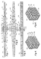
- Figure 1 is a top view in elevation of a first embodiment of an apertured strip for forming a packing body according to the invention;
- Figure 2 is a top view in elevation of a second embodiment of an apertured strip for forming a folded packing body;
- Figure 3 is a top view in elevation of a further embodiment of a strip for forming a folded packing body;
- Figure 4 is a perspective view of a folded packing body formed from the strip of Figure 3;
- Figure 5 is a top view in elevation of another embodiment of a strip for forming a folded packing body;
- Figure 6 is a perspective view of a packing body formed by folding the strip of Figure 5;
- Figure 7 is a perspective view of the strip of Figure 2 folded into a packing body;
- Figure 8 is a perspective view of a packing body formed from folding the strip of Figure 1;
- Figure 9 is a top view of another embodiment of a strip containing a plurality of rod-like projections;
- Figure 10 is a perspective view of a folded packing body formed from the strip of Figure 9;
- Figure 11 is a top view in elevation of yet another embodiment of an apertured strip with attached plates;
- Figure 12 is a perspective assembly view of the folded strip of Figure 11 joined to the plates;
- Figure 13 is a top view in elevation of an expandable strip with slits; and
- Figure 14 is a top view of an expanded metal strip.
- Referring now to Figures 1 and 8, the
improved packing body 10 is formed of astrip 12 having at least 30% open space provided byapertures 14. Thestrip 12 can have a thickness from 0.1 to 15mm. In the case of metal, the thickness is usually from 0.2 to 0.4mm. In the case of plastic, the thickness is usually from 0.5 to 3mm, preferably 1 to 2mm and in the case of ceramic, the strip has a thickness from 2 to 8mm. - The
strip 12 may also include baffle elements that project from thesurface 18 of thestrip 12 such as rod like struts or polygonal elements such asrectangular baffles 16. The strip is continuous from afirst end wall 20 to asecond end wall 22. The strip is divided intosegments 21 separated by foldingbands 23. The bands may contain atransverse slot 25 and can contain a score line, not shown, to act as a live hinge. Themedial segment 27 which is usually the middle segment can contain a pair ofside segments body 10 is formed by folding thefront segment 31 adjacent themedial segment 27 alongfold band 23 at a right angle to the longitudinal axis of thestrip 12 until thetop surface 33 of thesegment 31 is substantially parallel to thetop surface 35 of themedial segment 27. Thefolding band 23 will form acurved side edge 37 containingslot 25. - The next
adjacent front segment 40 is then folded along foldingband 42 toward thesegment 31 until the original bottom surface of the segment 41 is substantially parallel to the foldedsegment 31. Foldedband 42 forms a secondcurved side edge 44 containing aslot 25.Front segments - The
rear segments first folding segment 52 alongband 62 such that thebottom surface 64 of thesegment 52 is substantially parallel to the bottom surface of themedial segment 27. The foldedband 23 forms acurved edge 62.Segments bands 23 to form a stack of segments connected by curved side joints.Lower side segment 32 is folded alongslot 64 until thelower edge 66 is adjacent theend rear segment 60.Upper side segment 29 is folded along theslot 68 until theupper edge 70 of the side segment is adjacent theend front segment 50. - The strip has a pattern of
apertures 14 formed by raisedrectangular baffle elements 16. The baffle elements in this embodiment of a packing body are disposed parallel to the longitudinal axis of the strip. The baffle elements are attached to the surface of the strip along anedge 43 which is joined to the strip. The baffle elements may project upwardly, downwardly or some may project upwardly and some may project downwardly. - The length and width of the
strip 12 are determined by the nominal diameter and height desired for the packingbody 10, the size of segments and the surface area. Packing bodies generally have a diameter from 1 to 12 inches and the height is about 1 to 10 inches. Usually the diameter to height ratio is at least 1. A packing body will generally have a packing factor from about 3 to 65 per foot and a surface area from about 10 to 200 ft2/cu.ft. - The width of the strip at its widest dimension corresponds to the height of the packing body. Generally, the strip will be at least 5 inches long up to 100 inches or more. The spacing between folded segments depends on the height of the baffle elements. Generally, the baffle elements have a height from 1/16 to 2.0 inches. The packing body will have at least 2 segments preferably from 3 to 30 segments. Random packing bodies are generally from 1 to 5 inches in nominal diameter, have a height from 1 to 4 inches and a baffle from 1/16 to 3/4 of an inch. The method of the invention could also be used to produce large molecular structured packing bodies in cubic or rectangular-shaped modules such as 1' x 1' x 1'; 2' x 1' x 1' or 3' x 1' x 1'. The structured modules are placed one module at a time into the tower until the tower is filled.
- The strip can be in the form of a rectangle having parallel side walls as in Figures 3 and 5 or the strip can have shaped sided walls such as convex, concave, patterned or converging as in Figure 2. The segments of the strip can step down in width in discrete steps as in Figure 1. If the side walls of the strip are parallel, the strip will fold into a cubic or rectangular-shaped body. If the strip has tapered or stepped side walls, it will fold into an x-shaped structure if the smaller medial segment is disposed to the interior and into a polygon-shaped body if the larger medial segment is disposed to the interior of the packing
body 10 as shown in Figures 7 and 8. - The strip shown in Figures 9 and 10 has a very open structure like a mesh or a screen. In the embodiments shown in Figures 1-8, the strip is formed of sheet material. The baffle elements and the apertures can be formed by stamping and bending appropriate materials such as metal, certain plastics and certain precursor ceramics or they can be formed by molding in simple molding cavities or by casting. The apertures are formed in sheet material raised from the surface along integral connection joints to form the baffle elements. In the case of bendable materials, the baffle element can be cut along three sides and bent along the fourth side to form the apertures.
- In Figures 1, 3 and 5 the baffle elements are shown bent away from the surface of the strip along a connection joint parallel to the longitudinal axis of the strip. In Figure 2, the
baffle elements 82 are shown withcut lines 84 along 3 sides joiningbend line 86 which is at a 45 degree angle to the longitudinal axis of the strip. - The
rectangular strip 90 of Figure 3 is similar to the stepped downstrip 12 of Figure 1. When thestrip 90 is folded as in Figure 1 it will form arectangular packing body 92 as shown in Figure 4 with thefront segments 94 folded on top of themedial segment 95 to form atop stack 96 withside segment 98 folded upwardly. Therear segments 100 similarly fold downwardly to form abottom stack 102 withside segment 104 folded downwardly. - Figure 5 is similar to Figure 3 except that the
side segments rear segment 116. Thefront segments 119 are alternately folded on top of themedial segment 118 to form atop stack 93 and therear segments 121 are alternately folded on the bottom of themedial segment 118 to form a bottom stack as shown in Figure 6. Theside segment 110 is then folded downwardly along the side edges of the stack and theside segment 112 is folded upwardly along the opposite side edges of the stack to form apacking body 97. - The
strip 120 shown in Figure 2 is tapered in both directions. It has amedial segment 122 and adjacent front andrear segments bands 128 separating the segments. Thebaffle elements 82 are rectangular with the sides rotated 45 degrees with respect to the longitudinal axis of thestrip 120. - When the
top segments 124 are folded and stacked on top of themedial segment 122 and the bottom segments are folded and stacked along the bottom of themedial segment 122. A packingbody 140 having hexagon cross-section as shown in Figure 7 is formed. Theside segment 123 is folded upwardly and theother side segment 125 is folded downwardly. - If the strip is formed of resilient material, the shape of the packing body can be stabilized by providing latches between apertures in adjacent segments by securing the side edges of the segments to each other or to the medial segment or by securing the side edges of the segments to the side segments by mechanical latches, adhesives or thermal bonding in the case of thermoplastic resins or metals.
- A further embodiment of a packing body is shown in Figures 9 and 10. A
strip 200 has a very open structure provided byapertures 202. A pattern of rod-like baffle elements 204 are raised from thesurface 206 of thestrip 200. Some of theelements 207 are longer and are adapted to enter anaperture 205 in an opposed segment and latch the segments together. - Each segment is separated from the adjacent segment by a
band 208 containing a set ofparallel score lines 210, 212. The band may also contain anelongated aperture 214. As shown in Figure 10 as thefirst front segment 216 is folded, theband 208 will fold along thelive hinge 220 formed at score line 210 and theband 208 will be disposed at a right angle to themedial segment 218. Thevertical band 208 will then fold alongscore line 212 at a right angle to thenext front segment 222 to form a secondlive hinge 224. Thefront segment 222 is bent to be disposed parallel to themedial segment 218. - Some of the
longer baffle elements 207 projecting from the surface of themedial segment 218 are snapped into theopposed apertures 205 in the foldedsegment 216. Therear segments packing body 250 shown in Figure 10. - Another method of assembling a packing body is shown in Figures 11 and 12. A
strip 400 has threesegments apertures 408 and baffles 410 and a series ofpanels tabs 405 betweenprojections 407. Thepanels apertures 408 and baffles 410. Theend segments fold lines u-shaped shell 409. Thepanels tabs 405. Theindividual panels medial segment 404 are placed within theshell 409 in a position parallel to themedial segment 404. Theside projections 407 are inserted into theapertures 408 in thesegments packing body 430. The individual segments could be adhered together with a set of side strips or individual side plates or segments. - Another way to form an apertured, baffled strip in a single operation is shown in Figures 13 and 14. A
strip 300 of expandable material such as metal contains a pattern ofslits 302. Theslits 302 are preferably disposed transverse to the longitudinal axis of thestrip 300. Theslits 303 in afirst row 304 overlap theends 306 of twoslits 308 in anadjacent row 310. As thestrip 300 is expanded thepanels 312 between slits such as 303 and 306 in adjacent rows will tilt upwardly to form baffle elements 314 andapertures 316. Thestrip 300 can be rolled to form a cylindrical packing body or folded alongfold lines - The invention provides high performance packing bodies in complex shapes by simple, low cost fabrication techniques. The intricate shapes are defined in planer materials readily formed by casting, molding, stamping or extrusion. The manufacture is completed by a simple folding step. By use of strips having different widths, lengths or thicknesses, packing bodies having complex shapes can be produced. Packing bodies of different sizes can be filled into a tower.
- It is to be realized that only preferred embodiments of the invention have been described and that numerous substitutions, modifications and alterations are permissible without departing from the spirit and scope of the invention as defined in the following claims.
Claims (23)
- A packing body for use in fluid contact comprising in combination:a plurality of individual panels containing a pattern of apertures;fluid baffle means raised from the top and/or bottom surfaces of the panels;means spacing a plurality of the panels into a stacked arrangement with the panels substantially parallel to each other; andmeans projecting from a surface of the panels latching the panels together.
- A packing body according to claim 1 in which the fluid baffle means comprise a plurality of rod-like elements projecting from a surface of the panels.
- A packing body according to claim 2 in which the means spacing a plurality of the panels into a stack comprises a portion of the rod-like elements which are longer than other of said elements.
- A packing body according to claim 3 in which the longer rods enter an aperture in the opposed panel to latch said panels together.
- A packing body according to claim 4 in which said rods are cylindrical.
- A packing body according to claim 1 molded from synthetic organic resin.
- A packing body according to claim 1 having at least 30% open space.
- A packing body according to claim 1 comprising:an elongated, continuous strip having a pattern of apertures formed through the strip and said strip being divided into at least two panel segments along the longitudinal axis with a medial panel segment having a front edge and a rear edge transverse to said longitudinal axis;a first front panel segment adjacent the front edge; anda fold present in said first front panel segment along said front edge to fold said first front panel segment toward the top surface of the medial panel segment until said first front panel segment is substantially parallel to said top surface.
- A packing body according to claim 8 in which said strip is divided into at least three panel segments, a first rear panel segment is adjacent said rear edge and a fold is present in said first rear panel segment along said rear edge to fold said first rear panel segment toward the bottom surface of the medial segment until said first rear segment is substantially parallel to said bottom surface.
- A packing body according to claim 8 in which the segments adjacent the medial segment have a width smaller than the width of the medial segment.
- A packing body according to claim 8 including 1-10 front panel segments consecutively connected along the longitudinal axis, adjacent front panel segments having a common edge and being folded along said common edge with the bottom surface thereof facing the top surface of the preceding folded panel segment and including 1-10 rear panel segments consecutively connected along the longitudinal axis, adjacent rear panel segments having a common edge and being folded along said common edge with the top surface thereof facing the bottom surface of the preceding folded panel segment.
- A packing body according to claim 8 in which the fluid baffle elements are formed of strip material disposed upwardly and away from the top or bottom surface of the strip.
- A packing body according to claim 8 in which the fluid baffle elements are molded with the strip.
- A packing body according to claim 8 in which at least some of the fluid baffle elements are perpendicular to the longitudinal axis of the panels.
- A packing body according to claim 8 in which the strip is formed of metal, synthetic resin or ceramic.
- A packing body according to claim 1 in which the apertures are elongated slots disposed transverse to the longitudinal axis of the strip.
- A packing body according to claim 8 further including a live hinge being disposed along at least one of said folds.
- A packing body according to claim 17 in which said fold includes a pair of parallel live hinges spaced on each side of a transverse band of strip material and said band forms an angle of about 90 degrees with the surface of adjacent segments.
- A packing body according to claim 8 further including at least one side panel joined to a side edge of one of the stacked panels and being folded adjacent the edges of the stacked panels.
- A method of forming a packing body according to claim 1 for use in fluid contact comprising the steps of:forming an elongated, continuous strip of flexible, foldable material having a pattern of apertures;providing fold lines spaced along the longitudinal axis of the strip to form panel segments having fold lines on each front edge thereof; andfolding the strip along a front fold line between a first front panel segment and a second panel segment of the strip until the top surface of a front panel segment adjacent the second panel segment is substantially parallel to the top surface of the second panel segment.
- A method according to claim 20 in which the second segment is a medial panel segment and each panel segment has a fold line on each front and rear edge thereof; andfolding the strip along a rear fold line of the medial panel segment until the bottom surface of a rear panel segment adjacent the medial panel segment is substantially parallel to the bottom surface of the medial panel segment.
- A method of manufacturing a packing body according to clam 1 for use in fluid contact comprising the steps of:forming slits in an elongated strip of material;stretching the strip along the longitudinal axis such that the slits expand into elongated slots and the strip material between adjacent slots are raised from the surface at an angle from 10 degrees to 80 degrees; andfolding the strip along fold lines transverse to the longitudinal axis of the strip until adjacent panel segments are substantially parallel to each other.
- A method of forming a packing body according to claim 1 for use in fluid contact comprising the steps of stamping a continuous strip to form baffles and fold lines forming panel segments;raising the baffles from the surface of the strip; andfolding the strip along the fold lines until the panel segments are substantially parallel to each other.
Priority Applications (8)
| Application Number | Priority Date | Filing Date | Title |
|---|---|---|---|
| DE1070536T DE1070536T1 (en) | 1995-09-11 | 1995-09-11 | Foldable packing |
| EP00116907A EP1070536B1 (en) | 1995-09-11 | 1995-09-11 | Folded packing |
| DE69523913T DE69523913T2 (en) | 1995-09-11 | 1995-09-11 | Foldable packing |
| AT00116907T ATE252941T1 (en) | 1995-09-11 | 1995-09-11 | FOLDABLE FILLING BODY |
| EP95306344A EP0761301B1 (en) | 1995-09-11 | 1995-09-11 | Folded packing |
| AT95306344T ATE208655T1 (en) | 1995-09-11 | 1995-09-11 | FOLDABLE FILLING BODY |
| DE69532051T DE69532051T2 (en) | 1995-09-11 | 1995-09-11 | Foldable packing |
| ES00116907T ES2209731T3 (en) | 1995-09-11 | 1995-09-11 | FILLED FILLING BODY. |
Applications Claiming Priority (1)
| Application Number | Priority Date | Filing Date | Title |
|---|---|---|---|
| EP95306344A EP0761301B1 (en) | 1995-09-11 | 1995-09-11 | Folded packing |
Related Child Applications (1)
| Application Number | Title | Priority Date | Filing Date |
|---|---|---|---|
| EP00116907A Division EP1070536B1 (en) | 1995-09-11 | 1995-09-11 | Folded packing |
Publications (2)
| Publication Number | Publication Date |
|---|---|
| EP0761301A1 true EP0761301A1 (en) | 1997-03-12 |
| EP0761301B1 EP0761301B1 (en) | 2001-11-14 |
Family
ID=8221318
Family Applications (2)
| Application Number | Title | Priority Date | Filing Date |
|---|---|---|---|
| EP95306344A Expired - Lifetime EP0761301B1 (en) | 1995-09-11 | 1995-09-11 | Folded packing |
| EP00116907A Expired - Lifetime EP1070536B1 (en) | 1995-09-11 | 1995-09-11 | Folded packing |
Family Applications After (1)
| Application Number | Title | Priority Date | Filing Date |
|---|---|---|---|
| EP00116907A Expired - Lifetime EP1070536B1 (en) | 1995-09-11 | 1995-09-11 | Folded packing |
Country Status (4)
| Country | Link |
|---|---|
| EP (2) | EP0761301B1 (en) |
| AT (2) | ATE252941T1 (en) |
| DE (3) | DE1070536T1 (en) |
| ES (1) | ES2209731T3 (en) |
Cited By (2)
| Publication number | Priority date | Publication date | Assignee | Title |
|---|---|---|---|---|
| EP1152205A2 (en) * | 2000-05-04 | 2001-11-07 | Spig Foreign Markets S.r.l. | Filling for cooling towers |
| WO2020260434A1 (en) * | 2019-06-26 | 2020-12-30 | Total Raffinage Chimie | Lining placed inside a chamber to promote contact between circulating fluids |
Families Citing this family (3)
| Publication number | Priority date | Publication date | Assignee | Title |
|---|---|---|---|---|
| DE102010063074B3 (en) * | 2010-12-14 | 2012-04-12 | INSTITUT FüR MIKROTECHNIK MAINZ GMBH | Microfluidic component, reactor of several such components and method for their preparation |
| US9266083B2 (en) * | 2011-12-28 | 2016-02-23 | Uop Llc | Apparatuses for stripping gaseous hydrocarbons from particulate material and processes for the same |
| DE102019006414B4 (en) * | 2019-09-11 | 2021-09-23 | Blum-Novotest Gmbh | ADJUSTMENT DEVICE AND CHIPPING SYSTEM |
Citations (5)
| Publication number | Priority date | Publication date | Assignee | Title |
|---|---|---|---|---|
| DE1519668A1 (en) * | 1966-07-06 | 1970-10-29 | Magyar Asvanyolaj Es Foeldgaz | Filler for rectification columns |
| US4195043A (en) * | 1979-01-17 | 1980-03-25 | Norton Company | Randomly dumpable self orienting spiral packing elements |
| EP0150900A1 (en) * | 1984-01-04 | 1985-08-07 | Dale Edward Nutter | Gas-liquid contact apparatus and method of making it |
| US4724593A (en) | 1986-09-02 | 1988-02-16 | Lang Ko C | Method and blank for the manufacture of high efficiency open volumed packing bodies |
| WO1995012451A1 (en) * | 1993-11-03 | 1995-05-11 | Lantec Products, Inc. | Improved packing |
-
1995
- 1995-09-11 DE DE1070536T patent/DE1070536T1/en active Pending
- 1995-09-11 EP EP95306344A patent/EP0761301B1/en not_active Expired - Lifetime
- 1995-09-11 AT AT00116907T patent/ATE252941T1/en not_active IP Right Cessation
- 1995-09-11 EP EP00116907A patent/EP1070536B1/en not_active Expired - Lifetime
- 1995-09-11 DE DE69532051T patent/DE69532051T2/en not_active Expired - Fee Related
- 1995-09-11 ES ES00116907T patent/ES2209731T3/en not_active Expired - Lifetime
- 1995-09-11 DE DE69523913T patent/DE69523913T2/en not_active Expired - Fee Related
- 1995-09-11 AT AT95306344T patent/ATE208655T1/en not_active IP Right Cessation
Patent Citations (6)
| Publication number | Priority date | Publication date | Assignee | Title |
|---|---|---|---|---|
| DE1519668A1 (en) * | 1966-07-06 | 1970-10-29 | Magyar Asvanyolaj Es Foeldgaz | Filler for rectification columns |
| US4195043A (en) * | 1979-01-17 | 1980-03-25 | Norton Company | Randomly dumpable self orienting spiral packing elements |
| EP0150900A1 (en) * | 1984-01-04 | 1985-08-07 | Dale Edward Nutter | Gas-liquid contact apparatus and method of making it |
| US4724593A (en) | 1986-09-02 | 1988-02-16 | Lang Ko C | Method and blank for the manufacture of high efficiency open volumed packing bodies |
| EP0259022A2 (en) * | 1986-09-02 | 1988-03-09 | Ko Chieh Lang | Method and blank for the manufacture of high efficiency open volumed packing bodies |
| WO1995012451A1 (en) * | 1993-11-03 | 1995-05-11 | Lantec Products, Inc. | Improved packing |
Cited By (4)
| Publication number | Priority date | Publication date | Assignee | Title |
|---|---|---|---|---|
| EP1152205A2 (en) * | 2000-05-04 | 2001-11-07 | Spig Foreign Markets S.r.l. | Filling for cooling towers |
| EP1152205A3 (en) * | 2000-05-04 | 2002-06-12 | Spig Foreign Markets S.r.l. | Filling for cooling towers |
| WO2020260434A1 (en) * | 2019-06-26 | 2020-12-30 | Total Raffinage Chimie | Lining placed inside a chamber to promote contact between circulating fluids |
| FR3097777A1 (en) * | 2019-06-26 | 2021-01-01 | Total Raffinage Chimie | PADDING PROVIDES AN ENCLOSURE INSIDE TO PROMOTE CONTACT BETWEEN FLUIDS IN CIRCULATION |
Also Published As
| Publication number | Publication date |
|---|---|
| EP1070536B1 (en) | 2003-10-29 |
| EP0761301B1 (en) | 2001-11-14 |
| DE69532051D1 (en) | 2003-12-04 |
| DE69523913T2 (en) | 2002-07-04 |
| DE69523913D1 (en) | 2001-12-20 |
| ES2209731T3 (en) | 2004-07-01 |
| DE1070536T1 (en) | 2001-07-05 |
| ATE208655T1 (en) | 2001-11-15 |
| DE69532051T2 (en) | 2004-07-08 |
| ATE252941T1 (en) | 2003-11-15 |
| EP1070536A1 (en) | 2001-01-24 |
Similar Documents
| Publication | Publication Date | Title |
|---|---|---|
| US5714097A (en) | Packing | |
| US5458817A (en) | Folding packing and method of manufacture | |
| US6241222B1 (en) | Stacked packing with spacing features | |
| US5637263A (en) | Multifold packing and method of forming | |
| US4519960A (en) | Expanded metal saddle tower packing | |
| EP0259022B1 (en) | Method and blank for the manufacture of high efficiency open volumed packing bodies | |
| US3957931A (en) | Fluid-fluid contact method and apparatus | |
| JP4084849B2 (en) | Structured packing | |
| US5217788A (en) | Corrugated sheet assembly | |
| JP2573546B2 (en) | Disordered filling element and fabrication method | |
| JP2000234877A (en) | Fluid retaining louver assembly for heat mass transfer/ contact unit, fog remover, filling sheet and spacer | |
| JPS5811001A (en) | Filler for mass exchange tower and production thereof | |
| KR100359536B1 (en) | Film fill-pack for inducement of spiraling gas flow in heat and mass transfer contact apparatus with self-spacing fill-sheets | |
| JPS60243495A (en) | Film charging sheet for cooling tower for water and film charging pack | |
| EP1070536B1 (en) | Folded packing | |
| AU711580B2 (en) | Tower packing element | |
| US4385012A (en) | Phase-contacting apparatus | |
| KR100338718B1 (en) | Film fill-pack for inducement of spiraling gas flow in heat and mass transfer contact apparatus with self-spacing fill-sheets | |
| CA2157743C (en) | Folded packing and method of manufacture | |
| AU709351B2 (en) | Folded packing | |
| JP2004515339A (en) | Improved random filling element | |
| US4316863A (en) | Tower packing elements | |
| WO1995012451A1 (en) | Improved packing | |
| US20030146524A1 (en) | Plastic random packing element | |
| JP3550224B2 (en) | Filler body |
Legal Events
| Date | Code | Title | Description |
|---|---|---|---|
| PUAI | Public reference made under article 153(3) epc to a published international application that has entered the european phase |
Free format text: ORIGINAL CODE: 0009012 |
|
| AK | Designated contracting states |
Kind code of ref document: A1 Designated state(s): AT CH DE ES FR GB IT LI NL SE |
|
| 17P | Request for examination filed |
Effective date: 19970614 |
|
| 17Q | First examination report despatched |
Effective date: 19990701 |
|
| GRAG | Despatch of communication of intention to grant |
Free format text: ORIGINAL CODE: EPIDOS AGRA |
|
| GRAG | Despatch of communication of intention to grant |
Free format text: ORIGINAL CODE: EPIDOS AGRA |
|
| GRAH | Despatch of communication of intention to grant a patent |
Free format text: ORIGINAL CODE: EPIDOS IGRA |
|
| GRAH | Despatch of communication of intention to grant a patent |
Free format text: ORIGINAL CODE: EPIDOS IGRA |
|
| GRAA | (expected) grant |
Free format text: ORIGINAL CODE: 0009210 |
|
| AK | Designated contracting states |
Kind code of ref document: B1 Designated state(s): AT CH DE ES FR GB IT LI NL SE |
|
| PG25 | Lapsed in a contracting state [announced via postgrant information from national office to epo] |
Ref country code: LI Free format text: LAPSE BECAUSE OF FAILURE TO SUBMIT A TRANSLATION OF THE DESCRIPTION OR TO PAY THE FEE WITHIN THE PRESCRIBED TIME-LIMIT Effective date: 20011114 Ref country code: CH Free format text: LAPSE BECAUSE OF FAILURE TO SUBMIT A TRANSLATION OF THE DESCRIPTION OR TO PAY THE FEE WITHIN THE PRESCRIBED TIME-LIMIT Effective date: 20011114 Ref country code: AT Free format text: LAPSE BECAUSE OF FAILURE TO SUBMIT A TRANSLATION OF THE DESCRIPTION OR TO PAY THE FEE WITHIN THE PRESCRIBED TIME-LIMIT Effective date: 20011114 |
|
| REF | Corresponds to: |
Ref document number: 208655 Country of ref document: AT Date of ref document: 20011115 Kind code of ref document: T |
|
| REG | Reference to a national code |
Ref country code: CH Ref legal event code: EP |
|
| REF | Corresponds to: |
Ref document number: 69523913 Country of ref document: DE Date of ref document: 20011220 |
|
| REG | Reference to a national code |
Ref country code: GB Ref legal event code: IF02 |
|
| PG25 | Lapsed in a contracting state [announced via postgrant information from national office to epo] |
Ref country code: SE Free format text: LAPSE BECAUSE OF FAILURE TO SUBMIT A TRANSLATION OF THE DESCRIPTION OR TO PAY THE FEE WITHIN THE PRESCRIBED TIME-LIMIT Effective date: 20020214 |
|
| PG25 | Lapsed in a contracting state [announced via postgrant information from national office to epo] |
Ref country code: ES Free format text: LAPSE BECAUSE OF FAILURE TO SUBMIT A TRANSLATION OF THE DESCRIPTION OR TO PAY THE FEE WITHIN THE PRESCRIBED TIME-LIMIT Effective date: 20020530 |
|
| REG | Reference to a national code |
Ref country code: CH Ref legal event code: PL |
|
| PLBE | No opposition filed within time limit |
Free format text: ORIGINAL CODE: 0009261 |
|
| STAA | Information on the status of an ep patent application or granted ep patent |
Free format text: STATUS: NO OPPOSITION FILED WITHIN TIME LIMIT |
|
| 26N | No opposition filed | ||
| PGFP | Annual fee paid to national office [announced via postgrant information from national office to epo] |
Ref country code: GB Payment date: 20050816 Year of fee payment: 11 |
|
| PGFP | Annual fee paid to national office [announced via postgrant information from national office to epo] |
Ref country code: FR Payment date: 20050831 Year of fee payment: 11 |
|
| PGFP | Annual fee paid to national office [announced via postgrant information from national office to epo] |
Ref country code: NL Payment date: 20050930 Year of fee payment: 11 Ref country code: DE Payment date: 20050930 Year of fee payment: 11 |
|
| PGFP | Annual fee paid to national office [announced via postgrant information from national office to epo] |
Ref country code: IT Payment date: 20060930 Year of fee payment: 12 |
|
| PG25 | Lapsed in a contracting state [announced via postgrant information from national office to epo] |
Ref country code: NL Free format text: LAPSE BECAUSE OF NON-PAYMENT OF DUE FEES Effective date: 20070401 |
|
| PG25 | Lapsed in a contracting state [announced via postgrant information from national office to epo] |
Ref country code: DE Free format text: LAPSE BECAUSE OF NON-PAYMENT OF DUE FEES Effective date: 20070403 |
|
| GBPC | Gb: european patent ceased through non-payment of renewal fee |
Effective date: 20060911 |
|
| NLV4 | Nl: lapsed or anulled due to non-payment of the annual fee |
Effective date: 20070401 |
|
| REG | Reference to a national code |
Ref country code: FR Ref legal event code: ST Effective date: 20070531 |
|
| PG25 | Lapsed in a contracting state [announced via postgrant information from national office to epo] |
Ref country code: GB Free format text: LAPSE BECAUSE OF NON-PAYMENT OF DUE FEES Effective date: 20060911 |
|
| PG25 | Lapsed in a contracting state [announced via postgrant information from national office to epo] |
Ref country code: FR Free format text: LAPSE BECAUSE OF NON-PAYMENT OF DUE FEES Effective date: 20061002 |
|
| PG25 | Lapsed in a contracting state [announced via postgrant information from national office to epo] |
Ref country code: IT Free format text: LAPSE BECAUSE OF NON-PAYMENT OF DUE FEES Effective date: 20070911 |