EP0761195B1 - Multifunctional wheelchair - Google Patents
Multifunctional wheelchair Download PDFInfo
- Publication number
- EP0761195B1 EP0761195B1 EP96202513A EP96202513A EP0761195B1 EP 0761195 B1 EP0761195 B1 EP 0761195B1 EP 96202513 A EP96202513 A EP 96202513A EP 96202513 A EP96202513 A EP 96202513A EP 0761195 B1 EP0761195 B1 EP 0761195B1
- Authority
- EP
- European Patent Office
- Prior art keywords
- wheelchair
- frame
- wheel
- wheelchair according
- support
- Prior art date
- Legal status (The legal status is an assumption and is not a legal conclusion. Google has not performed a legal analysis and makes no representation as to the accuracy of the status listed.)
- Expired - Lifetime
Links
Images


Classifications
-
- A—HUMAN NECESSITIES
- A61—MEDICAL OR VETERINARY SCIENCE; HYGIENE
- A61G—TRANSPORT, PERSONAL CONVEYANCES, OR ACCOMMODATION SPECIALLY ADAPTED FOR PATIENTS OR DISABLED PERSONS; OPERATING TABLES OR CHAIRS; CHAIRS FOR DENTISTRY; FUNERAL DEVICES
- A61G5/00—Chairs or personal conveyances specially adapted for patients or disabled persons, e.g. wheelchairs
- A61G5/10—Parts, details or accessories
- A61G5/1056—Arrangements for adjusting the seat
- A61G5/1062—Arrangements for adjusting the seat adjusting the width of the seat
-
- A—HUMAN NECESSITIES
- A61—MEDICAL OR VETERINARY SCIENCE; HYGIENE
- A61G—TRANSPORT, PERSONAL CONVEYANCES, OR ACCOMMODATION SPECIALLY ADAPTED FOR PATIENTS OR DISABLED PERSONS; OPERATING TABLES OR CHAIRS; CHAIRS FOR DENTISTRY; FUNERAL DEVICES
- A61G5/00—Chairs or personal conveyances specially adapted for patients or disabled persons, e.g. wheelchairs
- A61G5/08—Chairs or personal conveyances specially adapted for patients or disabled persons, e.g. wheelchairs foldable
- A61G5/0808—Chairs or personal conveyances specially adapted for patients or disabled persons, e.g. wheelchairs foldable characterised by a particular folding direction
- A61G5/0816—Chairs or personal conveyances specially adapted for patients or disabled persons, e.g. wheelchairs foldable characterised by a particular folding direction folding side to side, e.g. reducing or expanding the overall width of the wheelchair
-
- A—HUMAN NECESSITIES
- A61—MEDICAL OR VETERINARY SCIENCE; HYGIENE
- A61G—TRANSPORT, PERSONAL CONVEYANCES, OR ACCOMMODATION SPECIALLY ADAPTED FOR PATIENTS OR DISABLED PERSONS; OPERATING TABLES OR CHAIRS; CHAIRS FOR DENTISTRY; FUNERAL DEVICES
- A61G5/00—Chairs or personal conveyances specially adapted for patients or disabled persons, e.g. wheelchairs
- A61G5/08—Chairs or personal conveyances specially adapted for patients or disabled persons, e.g. wheelchairs foldable
- A61G5/0883—Chairs or personal conveyances specially adapted for patients or disabled persons, e.g. wheelchairs foldable having locking means for maintaining a folded or unfolded condition
-
- A—HUMAN NECESSITIES
- A61—MEDICAL OR VETERINARY SCIENCE; HYGIENE
- A61G—TRANSPORT, PERSONAL CONVEYANCES, OR ACCOMMODATION SPECIALLY ADAPTED FOR PATIENTS OR DISABLED PERSONS; OPERATING TABLES OR CHAIRS; CHAIRS FOR DENTISTRY; FUNERAL DEVICES
- A61G5/00—Chairs or personal conveyances specially adapted for patients or disabled persons, e.g. wheelchairs
- A61G5/08—Chairs or personal conveyances specially adapted for patients or disabled persons, e.g. wheelchairs foldable
- A61G5/0891—Chairs or personal conveyances specially adapted for patients or disabled persons, e.g. wheelchairs foldable having rigid supports, e.g. seat or back supports which retain their shape after folding of the wheelchair
-
- A—HUMAN NECESSITIES
- A61—MEDICAL OR VETERINARY SCIENCE; HYGIENE
- A61G—TRANSPORT, PERSONAL CONVEYANCES, OR ACCOMMODATION SPECIALLY ADAPTED FOR PATIENTS OR DISABLED PERSONS; OPERATING TABLES OR CHAIRS; CHAIRS FOR DENTISTRY; FUNERAL DEVICES
- A61G5/00—Chairs or personal conveyances specially adapted for patients or disabled persons, e.g. wheelchairs
- A61G5/10—Parts, details or accessories
- A61G5/1054—Large wheels, e.g. higher than the seat portion
-
- A—HUMAN NECESSITIES
- A61—MEDICAL OR VETERINARY SCIENCE; HYGIENE
- A61G—TRANSPORT, PERSONAL CONVEYANCES, OR ACCOMMODATION SPECIALLY ADAPTED FOR PATIENTS OR DISABLED PERSONS; OPERATING TABLES OR CHAIRS; CHAIRS FOR DENTISTRY; FUNERAL DEVICES
- A61G5/00—Chairs or personal conveyances specially adapted for patients or disabled persons, e.g. wheelchairs
- A61G5/10—Parts, details or accessories
- A61G5/1056—Arrangements for adjusting the seat
- A61G5/1075—Arrangements for adjusting the seat tilting the whole seat backwards
-
- A—HUMAN NECESSITIES
- A61—MEDICAL OR VETERINARY SCIENCE; HYGIENE
- A61G—TRANSPORT, PERSONAL CONVEYANCES, OR ACCOMMODATION SPECIALLY ADAPTED FOR PATIENTS OR DISABLED PERSONS; OPERATING TABLES OR CHAIRS; CHAIRS FOR DENTISTRY; FUNERAL DEVICES
- A61G5/00—Chairs or personal conveyances specially adapted for patients or disabled persons, e.g. wheelchairs
- A61G5/10—Parts, details or accessories
- A61G5/1091—Cushions, seats or abduction devices
-
- A—HUMAN NECESSITIES
- A61—MEDICAL OR VETERINARY SCIENCE; HYGIENE
- A61G—TRANSPORT, PERSONAL CONVEYANCES, OR ACCOMMODATION SPECIALLY ADAPTED FOR PATIENTS OR DISABLED PERSONS; OPERATING TABLES OR CHAIRS; CHAIRS FOR DENTISTRY; FUNERAL DEVICES
- A61G5/00—Chairs or personal conveyances specially adapted for patients or disabled persons, e.g. wheelchairs
- A61G5/10—Parts, details or accessories
- A61G5/12—Rests specially adapted therefor, e.g. for the head or the feet
- A61G5/128—Rests specially adapted therefor, e.g. for the head or the feet for feet
Definitions
- the height and the angle at which the seat and backrest are arranged relative to the ground can be adapted, at the same time adjusting the length of the wheelbase correspondingly. Because upon increase of the height of the seat the length of the wheel base increases also, there is always obtained an optimum adjustment of the wheel base to the height of the wheelchair and thus of the location of the center of gravity during use. If the center of gravity is located higher, the wheel base in a wheelchair according to this embodiment is greater than if the center of gravity is located lower, which has a stabilizing effect.
Abstract
Description
- The present invention relates to a wheelchair of the type defined in the preamble of the main claim. Such a wheelchair is known from DE-U-8914424.4 as well as WO-A-9107936.
- This known wheelchair comprises two front wheels, carried in forks, which forks are attached to rotary shafts, rotatable around a substantially vertical axis. A connecting arm is provided between each shaft and a second substantially vertical axis, for adjustment of a slight angle of the rotary shaft relative to a vertical lign. A row of holes above each other is provided for adjustment of the vertical distance between the horizontal axis of the frontwheels and the seating height, independently from the position of said arm. This adjustment has to be accompanied by a similar adjustment of the position of the rear wheels, relative to the frame, in order to maintain the desired position of the rotary shafts.
- It is an object of the invention to provide a wheelchair according to the preamble of claim 1, avoiding the drawbacks of the known wheelchair, maintaining the advantages thereof. To this end, a wheelchair according to the invention is characterized by the features of claim 1.
- By adjusting the adjustment means of at least the front wheels of the wheelchair, the height and the angle at which the seat and backrest are arranged relative to the ground can be adapted, at the same time adjusting the length of the wheelbase correspondingly. Because upon increase of the height of the seat the length of the wheel base increases also, there is always obtained an optimum adjustment of the wheel base to the height of the wheelchair and thus of the location of the center of gravity during use. If the center of gravity is located higher, the wheel base in a wheelchair according to this embodiment is greater than if the center of gravity is located lower, which has a stabilizing effect.
- In an advantageous embodiment a wheelchair is characterized according to the invention by the features according to claims 2 - 6.
- By adjusting both the front and the rear wheels relative to the seat and the backrest, both the angle which the seat and backrest include with the ground and the height thereof above the ground can be adjusted individually, that is, independently of each other.
- The known wheelchair has swiveling front wheels. A drawback of this known wheelchair is that the location of the wheel axle of each front wheel relative to the swivel pin is fixed. The steering and riding behaviour can only be adjusted slightly by means of the connecting arm. The position of the wheel axles relative to the swivel pins is therefore mostly a compromise between optimum manoeuvrability, e.g. for use of the wheelchair indoors, and optimum stability and tracking, e.g. for use of the wheelchair for longer distances.
- It is a further object of the invention to provide a wheelchair in which the position of the wheel axle relative to the swivel pin is better adjustable. This object is achieved in a wheelchair according to the invention through the features according to
claim 7. - Because the fork is pivotally connected via the second swiveling means with the first swiveling means, the position of the fork can easily be adapted to the individual user. At least two advantages can thus be obtained.
- Firstly, if desired, the riding behaviour of the wheelchair can be influenced by the user. By positioning the wheel axle closer to the produced part of the first axis of rotation, a more direct steering is obtained; by increasing the distance between the wheel axle and the first axis of rotation, riding straight on with the wheelchair is facilitated, so that e.g. the use for longer distances becomes more agreeable. Secondly, in particular in a wheelchair according to one of claims 1 - 6, the advantage is obtained that upon adjustment of the front and/or rear wheels the position of the wheel axles can be corrected, so that the same steering behaviour is maintained or can be adjusted.
- The known wheelchair has fixed dimensions and a limited number of sizes are available. Therefore, the same size of wheelchair is used for both tall and small users, which means that a user only very seldom has a wheelchair which suits him or her as to size. Changes to a wheelchair to adjust the dimensions are often not possible and at least expensive to perform. Moreover, such a wheelchair cannot readily be reused. In addition, such a necessary variety entails logistic and economic problems for at least the supplier.
- It is therefore a still further object of the invention to provide a wheelchair in which, using a limited number of standard parts, different wheelchairs can be obtained which are mutually different in one or a number of dimensions and can thus be easily adapted to the individual user, can be economically produced and used and enable an ergonomically suitable sitting and use posture. A wheelchair is then characterized by the features according to claim 9.
- The adjustability of the frame of the wheelchair in both width and length affords the possibility to each individual user to obtain optimum dimensions of the frame of the wheelchair, while use can be made of always substantially the same standard parts.
- In a first further elaboration, such a wheelchair is characterized by the features according to
claim 10. Thus, any length of the frame is obtainable, while only the coupling pieces to be included between the sections are different from each other. - In a second further elaboration, such a wheelchair is characterized by the features according to
claim 11. Since the connecting frame is width-adjustable, a variety of wheelchair widths can be obtained with the same standard connecting frame. - A wheelchair according to the invention is moreover preferably characterized by the features according to claim 12. Thus, transport and storage can be easily carried out, while yet a stable and form-retaining, easily operated wheelchair is obtained.
- When the known wheelchair is used in a stepping mariner, there is a risk that when a foot is being moved under the seat, the foot or the back of the leg comes into contact with a frame part, in particular a connecting part thereof. This is inconvenient, increases the risk of injuries and moreover reduces the convenience of use, because less large stepping paces can be made.
- It is therefore a further object of the invention to provide a wheelchair which can be easily and safely used through stepping, in an ergonomically sound manner. Thus a wheelchair according to the invention is characterized by the features according to
claim 13. - For the user known wheelchairs have a number of further drawbacks of an economic and ergonomic nature. In a configuration suitable for the intended user, the wheelchair is composed of a large number of parts. Where possible, standard parts are used, such as seats and backrests, frames, wheels, and the like. In general, individual adaptations to the wheelchair can only be effected to a limited degree and at high additional cost.
- The seat of the known wheelchair consists of a foamed upholstered cushion mounted on, e.g., a board. As a result, the shape of the seat and the sitting position of the user is mainly determined by the composition of the seat cushion and the covering, the shape of the board, and the position of the seat relative to the rest of the wheelchair. For a heavier user, for example, the sitting position will therefore be different than for a lighter user. Moreover, only an average suitable sitting support can be obtained. For separate sitting supports, especially adapted seats will have to be made in single-piece production, which is expensive and time-consuming, and moreover, prevents the same seat being used for different users.
- It is therefore an even further object of the invention to provide a wheelchair having a seat that is easy to adapt to the individual user, economic in its production and enables an ergonomically suitable sitting position. To this end, a wheelchair according to the invention is characterized by the features of
claim 14. - By means of the hinged flap the shape of the cushion can be adapted to the individual user. Thus, using a standard seat a suitable sitting support can be obtained for each user, while moreover adaptations are possible in a simple manner. If the same wheelchair (seat) must be made suitable for a next user, the shape of the seat can be simply adapted, so that a seat according to the invention has a prolonged service life. Also, a decrease of the resilience of the seat cushion can be compensated to some extent through changes in the position of the flap.
- The backrest of the known wheelchair has a structure comparable to that of the seat and entails comparable drawbacks. Also, the backrest is not individually adjustable and production of an individualized backrest is expensive and time-consuming.
- It is therefore another object of the invention to provide a wheelchair having a backrest that is easy to adapt to the individual user, economically produced and enables an ergonomically suitable sitting position. To this end, a wheelchair according to the invention is characterized by the features of
claim 17. - By means of the adjustable support straps, the form of the backrest can be individually determined and adapted, changes in the form being easy to perform.
- In a very advantageous embodiment, a wheelchair according to the invention is characterized by the features of claims 18-21.
- The length-adjustable support straps extending in approximately vertical direction and the length-adjustable lumbar strap, together with the adjustability of the points of attachment thereof along the support frame, provide optimum adjustability of the form of the backrest. Thus, by means of such a backrest an optimum back support can be obtained for each user. Even if the user has, e.g., a humpback or like deformity or certain spots which must hardly be loaded, if at all, or, conversely, need additional support, the backrest can be optimally adapted thereto. Particularly in combination with a sitting support as defined in claims 14-16 there is thus obtained a wheelchair capable of providing an excellent sitting support adjusted to the individual user without requiring considerable costs.
- An important factor in obtaining an optimum sitting and use position in a wheelchair for each user is the position of the sitting support relative to the ground. A wrong positioning of seat and/or backrest relative to the ground results in a wrong sitting position and moreover renders the operation and use of the wheelchair more difficult. Individual adjustment thereof is therefore important, the more so as a wrong posture may lead to the user being undesirably loaded which may cause injuries and discomfort.
- Other advantageous embodiments of a wheelchair according to the invention are given in the other claims and the specification.
- In elucidation of the invention, an exemplary embodiment of a wheelchair will be described with reference to the drawings, in which:
- Fig. 1 is a side view of a wheelchair according to the invention in a first position with a rear wheel removed;
- Fig. 2 is a side view of the wheelchair shown in Fig. 1 in a second position;
- Fig. 3 is a rear view of a wheelchair according to Figs. 1 and 2;
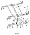
- Fig. 4 is a diagrammatic perspective view of a connecting frame of the wheelchair;
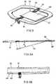
- Fig. 5 is a perspective view of a seat with the seat cushion removed;
- Fig. 6 is a cross-sectional side view of a seat and backrest, with mounted cushions;
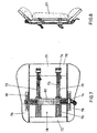
- Fig. 7 is a rear view of a backrest, with back cushion removed;
- Fig. 8 is a top plan view of a backrest as shown in Fig. 7, with back cushion placed;
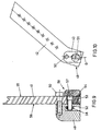
- Fig. 9 is a front view in partial cross-section of a suspension of a front wheel; and
- Fig. 10 is a side view of the suspension shown in Fig. 9.
-
- A wheelchair as shown in Figs. 1-3 comprises a support frame 1 built up from a number of tubular sections whose construction will be explained below in more detail, a pair of large
rear wheels 2, a pair of smallfront wheels 3 mounted for swiveling movement, aseat 4 and abackrest 5, foot rests 6, and handles 7. - The support frame 1 comprises two approximately
identical parts 8 spaced apart and approximately parallel to each other. Eachframe part 8 comprises twoseat tubes upper seat tube 9a continues at the rear side via an upwardly directedfirst bend 10. To thisfirst bend 10 connects, for instance, an armrest (Figs. 1-3). Attached adjacent thebend 10 via a set of toothed rings 100 is aback tube 11, which extends behind or laterally of thebackrest 5 and is capable of including an angle with the vertical, preferably in such a manner that theback tube 11, viewed in the direction of travel, is inclined backwards slightly. The angle of theback tubes 11 is adjustable by means of the toothed rings 100. At the top theback tube 11 is connected with ahandle 7 extending rearwards. At the front theupper seat tube 9a continues via a downwardly directedsecond bend 13 into afoot rest tube 14. Thefoot rest tube 14 includes an angle with the vertical, in such a manner that the lower end of thefoot rest tube 14 is disposed forward of thesecond bend 13. Adjacent its lower end thefoot rest tube 14 is provided with a collapsible foot rest 6 which is freely suspended above the ground. - Near the first bend 10 a
wheel frame 16 is mounted on the upper seat tube. Thewheel frame 16 comprises twosupport bars 17 extending approximately parallel to each other and downwards at right angles to theupper seat tube 9a, which support bars 17 are interconnected at the lower end by a cross-latch 18. The support bars are provided at regular intervals with fixingholes 19 through which awheel plate 20 can be fixed. Thewheel plate 20 has a central opening 12 in which arear wheel 2 is mounted. Thelower seat tube 9b extends in rearward direction from thefoot rest tube 14 as far as the support bars 17. - The seat tubes 9, an armrest, if present, the
foot rest tube 14 and thewheel frame 16 of eachframe part 8 are substantially disposed in one plane, which extends approximately vertically. Thewheel plate 20 is shaped in such a manner that therear wheel 2 includes an angle with the vertical plane mentioned, in such a manner that the distance between the twowheel plates 20 adjacent the ground is greater than is the distance at the upper end. Thus the stability of the wheelchair is increased. - The
frame parts 8 are interconnected by a connecting frame 21 (Figs. 3 and 4) which is so designed that the wheelchair is collapsible. The connectingframe 21 comprises two upper connectingbars 22, one on the side proximal to the front of the wheelchair and one near the back, and one lower connectingbar 23, near the back, approximately straight under the rearupper connecting bar 22. Each connectingbar frame halves 24 which in mirrored position are hingedly connected in acentral hinge point 25 adjacent the vertical median plane of the wheelchair. The end of each connectingframe half 24 remote from thecentral hinge point 25 is connected with aframe half 8 in aframe hinge point 26. The hinges of the central hinge points 25 and frame hinge points 26 are parallel to each other and to the longitudinal direction of the wheelchair, in such a manner that upon upward movement of the central hinge points 25 relative to the frame hinge points 26 the latter are drawn towards each other. In this manner, the frame halves 8 can be moved towards each other, so that the width of the wheelchair is reduced considerably. - The upper and lower central hinge points 25 located adjacent the rear of the wheelchair are interconnected through a
guide bar 27 which in a central area thereof is provided with aguide slot 28. At some distance from the lowercentral hinge point 25 each lower connectingframe half 24 is provided with anauxiliary hinge point 29 in which ahooked link 30 is pivotally mounted. The ends of thelinks 30 remote from the connectingframe halves 24 are connected through theguide slot 28 by means of acoupling bolt 31 for mutual hinging movement. Through this arrangement of theguide bar 27 andlinks 30 it is ensured that the twoframe halves 8 remain parallel to each other in each position of thecentral hinge point 25. Moreover, as a result, the freedom of movement of the central hinge points 25 in vertical direction is limited. If thecoupling bolt 31 is disposed at the upper end of theguide slot 28, the connectingframe 21 has the maximum width, if thecoupling bolt 31 is disposed at the lower end of theguide slot 28, the connectingframe 21, and hence the wheelchair, has the minimum width. Theguide bar 27 therefore prevents buckling of the connectingframe 21. - The upper connecting
bars 22 are interconnected by threelongitudinal bars 32. The central longitudinal bar connects the upper central hinge points 25 and extends in line with the hinges thereof. The wheelchair can be substantially folded up by pulling thislongitudinal bar 32 upwards. Through thelongitudinal bars 32, the connecting frame acquires sufficient stiffness in horizontal direction as well. - Each connecting
frame half 24 is made up of anouter tube 34 which is connected with acentral hinge point 25 and aninner tube 35, which is slidable within theouter tube 34 with a proper fit and is connected with aframe hinge point 26. By means of, for instance, a set bolt (not shown), theinner tube 35 can be secured in different positions displaced lengthwise with respect to theouter tube 34, through holes in the respective parts. As a result, the maximum width of the connectingframe 21 can be simply adapted to individual desires and prescriptions of users. - Each
frame half 8 is made up of afront section 36 and arear section 37. To that end, theseat tubes sections guide stub 38 is arranged which has an outside cross section substantially corresponding with the inside cross section of therespective seat tube tube stubs 38, in such a manner that the length of theseat tubes sections sections 36, 37 a fillingtube 15 can be arranged around the tube stubs 38 with a proper fit, in such a manner that, in any case visually, theseat tubes - By means of the connecting
frame 21 and the guide stubs 38 it is therefore possible to adapt both the width and the length of the wheelchair to the needs of the user. - Adjacent the front of the wheelchair, the upper 9a and
lower seat tube 9b are connected through afront wheel tube 40 which includes an angle with the vertical, which angle in the embodiment shown is slightly smaller than the angle between thefoot support tube 14 and the vertical. Slidably received within eachfront wheel tube 40 is a slidingpiece 41, which can be secured in different displaced positions, as appears from Figs. 1 and 2, where two positions are shown. The slidingpiece 41 comprises afirst part 42 which can extend within thefront wheel tube 40, and asecond part 43 which includes an angle with the first part, which angle corresponds approximately with the angle which the front wheel tube includes with the vertical. In the embodiment shown, these angles are about 66°. Accordingly, in assembled condition, thesecond part 43 of the slidingpiece 41 extends downwards approximately at right angles to theseat tubes - Each
front wheel 3 is mounted in a fork 44 which is provided at the top thereof with aswivel point 45. During operation, the swivel point defines a vertical axis of rotation D, with thearms 46 of the fork including an angle with the vertical. Accordingly, theaxle 47 of the front wheel, viewed in horizontal direction, is not located straight under theswivel point 45 but slightly to the side thereof. The angle which the fork 44 includes with the vertical and the length of the fork 44 determine the horizontal distance between the swivel point and theaxle 47, and hence the steering behaviour of the wheelchair. If this distance is small, the wheelchair becomes unstable in its steering behaviour; if the distance is large, the wheelchair is difficult to steer to negotiate a bend. Moreover, it is important that the axis of rotation D is oriented as vertically as possible because this makes steering lighter and moreover prevents wear. - Given the same position of the
rear wheels 2 relative to the wheel frames 16, upon length adjustment of the slidingpieces 41 within thefront wheel tubes 40, the position of the wheelchair will change. When the slidingpiece 41 is slid out, the wheelchair will tilt backwards, and when slid in, forwards. Thus, for instance the angle of inclination of the seat and the backrest can be set, which can have, for instance, ergonomic advantages. In case of such a tilt, the axis of rotation D of the front wheels would likewise tilt, which is disadvantageous, as described. Therefore, atilting mechanism 48 is provided on thesecond part 43 of the slidingpiece 41, which mechanism allows the axis of rotation D to be brought into a vertical position again upon sliding movement of the slidingpiece 41. - The
tilting mechanism 48 is arranged on the side of theswivel point 45 remote from the fork 44. Eachtilting mechanism 48 comprises aleg 49 which adjacent a first end is pivotally connected with thesecond part 43 of the slidingpiece 41 through a tiltingpin 50 extending horizontally and at right angles to the direction of travel of the wheelchair. The opposite, second end of the leg is connected to theswivel point 45. Thus, by pivoting theleg 49 about the tiltingpin 50 the orientation of the axis of rotation D can be adjusted. For the purpose of pivoting and securing the leg, an eccentric 51 is included between the tiltingpin 50 and theswivel point 45. - The eccentric 51 comprises a
rotary pin 53 of a relatively large cross section and with ahead 54 of greater cross section, which pin extends through an opening in thesecond part 43 of the slidingpiece 41. Thehead 54 of therotary pin 53 abuts against afirst side 55 of thesecond part 43 remote from theleg 49. The end of therotary pin 53 opposite thehead 54 is approximately flush with thesecond side 56 of thesecond part 43 of the slidingpiece 41, remote from thefirst side 55 of thesecond part 43. In the rotary pin 54 a hole has been drilled, located eccentrically, parallel to the longitudinal axis of therotary pin 54, through which hole extends abolt 57. Thisbolt 57 has itshead 58 abutting against the outside of thehead 54 of therotary pin 53. The threaded opposite end extends through afitting slot 52 in theleg 49. At the end of theleg 49 remote from the slidingpiece 41, anut 58 has been screwed onto thebolt 57. Upon rotation of therotary pin 53, thebolt 57 moves along around the axis of rotation of therotary pin 53 and through theslot 52. As a result, theleg 49 is pivoted around the tiltingpin 50 located at a distance from thebolt 57 and the axis of rotation of therotary pin 53, so that the angle which the axis of rotation D includes with the vertical can be simply adjusted. Upon adjustment of the angle (preferably to 0° with the vertical), thenut 58 and thebolt 57 can be screwed tight one within the other, to thereby fix the position. - By means of the
wheel plate 20, the height of the axle of eachrear wheel 2 can be adjusted relative to thewheel frame 16. To that end, the fixing bolts must be taken from the fixing holes 19 and secured again in other desired fixing holes 19. This also influences the inclination of the wheelchair, while the inclination and/or the position of the axes of rotation D can optionally be adjusted in the manner described in the foregoing. Accordingly, by means of, mainly, thewheel plates 20, the wheel frames 16, the slidingpieces 41 and thefront wheel tubes 40, it is possible to adjust the angle of inclination as well as the height of the wheelchair in a simple manner, while the orientation of the axes of rotation D of the front wheel forks 44 can be adjusted thereto by means of the eccentrics, which is of importance for the front wheels to track. - Because the
front wheel tube 40, viewed in the direction of travel, tilts backwards, an advantage is gained in that upon a height adjustment of the wheelchair, the length of the wheel base changes as well. If the front wheel is set "higher", that is, if the slidingpiece 41 is slid out further, the wheel base becomes longer. Accordingly, a wheelchair set "higher" becomes more stable, which is beneficial to the safety of the user. - The preferably
detachable seat 4 comprises aseat edge 60 supported by theupper seat tubes 9a, whichedge 60 leaves clear acentral opening 61. Mounted on the forward portion of theseat edge 60 is ahinge 62 by means of which aflap 63 is mounted for tilting movement within theopening 61 in the seat edge. Adjacent the side remote from thehinge 62, theflap 63 is supported by asupport strap 65 attached to thelongitudinal sides 64 of theseat edge 61. Thissupport strap 65 can be of slightly elastic construction and is length-adjustable, for instance by means of aclasp 66. If thesupport strap 65 has a minimum length, which means that it extends across the opening approximately in horizontal direction, theflap 63 is disposed approximately horizontally above theopening 61. If the length of thesupport strap 65 is increased, it will sag, so that theflap 64 will tilt within theopening 61. In other words, by means of thesupport strap 65, the angle of inclination a of theflap 64 can be set. - Placed on the
seat edge 60, theflap 64 and thesupport strap 65 is aseat cushion 67, consisting, for instance, of a first layer offoam 68 of a relatively high density and a second layer offoam 69 of a relatively low density, arranged on thefirst layer 68. When using the wheelchair, a user will sit on theseat cushion 67, whereby the layers of foam will be compressed slightly. If thesupport strap 65 is fully tightened, theflap 64 is approximately flush with theseat edge 60 and the user does not in effect experience any seat angle other than the angle that exists due to the angle of inclination of the wheelchair. If thesupport strap 65 is set less tight, the seat cushion will sag slightly along with theflap 64. As a result, a relatively greater angle of inclination of the seat is obtained. By making the support strap slightly elastic, additionally the spring and absorbing capacity of the wheelchair is influenced advantageously for the user. The use of theflap 64 andsupport strap 65 provides in a simple and economic manner for an increase of the ergonomic value of the wheelchair and moreover of the convenience in use and operation. The seat is comfortable and simple in use. It is noted that theflap 64 can also be designed in other ways, for instance as a number of straps extending between the front of theseat edge 60 and thesupport strap 65. - The
backrest 5 is provided with abackrest edge 70 which is mounted against theback tubes 11. Tensioned between the top 71 and bottom 72 of thebackrest edge 70 are a number ofstraps 73, two in the exemplary embodiment shown. Each strap is length-adjustable by means of astrap tensioner 74, and moreover preferably made up of a first,elastic part 75 and a second,non-elastic part 76. By means of thestrap tensioners 74, thestraps 73 can be adjusted in length in a manner similar to thesupport strap 65 of theseat 4, so that the degree of bending thereof upon loading can be set. The elasticfirst part 75 here provides for more comfort. Arranged against thebackrest edge 70 is aback cushion 77 which has a structure comparable to theseat cushion 67. Because twostraps 73 are arranged approximately parallel to each other, with each of the straps being individually length-adjustable, it is possible to control the compression of the left half and right half of thebackrest 5 separately, so that the shape and deformation of theback cushion 77 can be set individually and at any time for each user. For instance for people with deviantly shaped back portions and/or a higher risk of bed sores (decubitus), this is particularly advantageous because an optimum pressure distribution can be provided for. It is noted that theseat 4 too can, if desired, be comparably provided with two or more straps instead of, or in addition to, theflap 64. - In an alternative embodiment, not shown, the or each
strap 73 is laterally displaceable as well, in such a manner that the distance between each strap and the peripheral edges or the other straps, if any, can be adjusted. As a result, the shape of the supporting surface can be controlled even better. - In order to afford the user even more comfort and support, the
backrest 5 further comprises an adjustablelumbar support 78, which is formed by alumbar strap 80, extending between thesides 79 of thebackrest edge 70 and crossing thestraps 73, and which is likewise provided with astrap tensioner 74. Thelumbar strap 80 is attached to thesides 79 through bolts and two sliding nuts received in sliding rails 81. Each of the ends of thelumbar strap 80 is adjustable along the relevant slidingrail 81 and can be secured in any position. As a result, it is possible both to displace the lumbar strap straight along the surface of thebackrest 5, up and down, and to have it include an angle with the horizontal. In other words, for a user thelumbar strap 80, and hence thelumbar support 78, can be set higher and lower, simultaneously on the left and right side, as well as individually on either side, so that the lumbar support can be adapted to the individual user. Accordingly, in combination with thestraps 73 which are adjustable in vertical direction, it is possible through thelumbar support 78 to adapt the shape of theback cushion 77 to the individual user in an ideal manner, which is advantageous in particular for users with a deviant geometry of the back. - The
sides 79 of thebackrest edge 70 are slightly bent forwards for the purpose of augmenting the lateral support for the user, so that thebackrest 5 is tub-shaped to some extent. Theseat 4 can similarly be of tub-shaped design. - A wheelchair according to the invention can be used as follows.
- Two
frame parts 8 are assembled from a front 36 andrear section 37, with a filling tube being fitted between thesections relevant guide stubs 38 for the purpose of adjusting the length of theframe parts 8, depending on the intended user of the wheelchair. Then a connectingframe 21 is assembled, whose desired width is set by means of theouter tubes 34 andinner tubes 35, again depending on the intended user. This connectingframe 21 is assembled together with theframe parts 8 for forming the support frame 1. - On opposite sides of the support frame 1, a
wheel plate 20 is mounted on therelevant wheel frame 16 at a height depending on the intended user. Then in each wheel plate 20 a standard sizerear wheel 2 is mounted. These wheels may be provided with driving hoops. - In each front wheel tube 40 a sliding
piece 41 is mounted, on which a standardfront wheel 3 is pivotally mounted. The eccentric 51 is positioned in the slidingpiece 41. The slidingpiece 41 is adjusted in height through displacement thereof within thefront wheel tube 40, in such a manner that a desired angle of the support frame 1 is obtained. This desired angle will depend, for instance, on the intended user. Thereupon, in the manner described in the foregoing, by means of the eccentric 51 the position of the fork 44 which mounts thefront wheel 3 is adjusted in such a manner that the axis of rotation D extends approximately in vertical direction, whereafter the eccentric 51 is fixed by means of theset bolt 57 and associated nut. Thus a fully individually adapted wheelchair undercarriage is obtained. - On the
seat tubes 9 aseat 4 is mounted, with the length of the or eachsupport strap 65 being adjusted in such a manner that a suitable, convenient sitting angle for the intended user is obtained. In a comparable manner, abackrest 5 is mounted against theback tubes 11, and thestraps 73 and thelumbar support 78 thereof are suitably set, in such a manner that the shape of thebackrest 5 is optimal for the intended user. Further, the wheelchair can be provided, for instance, with armrests and a headrest and like accessories. In this way, a fully individually adapted wheelchair is obtained, which is made up of standard parts, which is favourable both from an economic and from an ergonomic point of view. - During use of the wheelchair by the user, it can be driven by rotation of the rear wheels, for instance by means of the hoops. It is also possible, however, to ride the wheelchair by stepping. When so used, this wheelchair has an advantage over known wheelchairs in that the support frame does not impede such stepping movement. This can be understood as follows.
- During stepping, at least one of the feet and a part of the associated leg of the user come under the seat. Owing to the fact that the connecting
frame 21 of a wheelchair according to the invention has only one rear lower connecting bar, the space under the seat adjacent the front of the wheelchair, and hence in the area where the or each foot and associated leg of the user will extend intermittently during the stepping movement, is free of obstacles. As a result, the user experiences no hindrance from the support frame during stepping. It is noted that it is naturally also possible to drive the wheelchair in other ways, for instance by means of a motor, by pushing or through lever drive. - For the purpose of transporting the wheelchair, it can be collapsed. To that end, the seat and backrest are removed or at least swung clear, whereafter the central
longitudinal bar 32 is gripped and pulled up. As a result, the twoframe parts 8 are moved towards each other and the wheelchair is rendered easy to transport. For the purpose of making the wheelchair ready for use from this position, the reverse procedure is followed. The wheelchair is preferred to be self-locking in the service position. - In an alternative embodiment, not shown, the angle of the front wheel forks is adjustable during use as well, for instance by means of a lever, while the axis of rotation D is maintained approximately vertical. As a result, during use, a switch can be made from an "indoor position" in which the wheelchair can be properly manoeuvred in that the front wheel fork extends approximately vertically and an "outdoor position" in which the fork includes an angle with the vertical, so that the wheelchair tracks right. To that end, use can be made of the eccentric described, or an additional, second swivel point can be included, with an axis of rotation approximately parallel to the wheel axle and located between the eccentric and the wheel axle.
- The invention is not in any way limited to the embodiments shown and described. Many modifications thereof are possible. For instance, the frame parts can be constructed differently, for instance wholly or partly from plate parts, the wheel frames can be of different design, and the foot support tube and the front wheel tube can be combined. Further, for instance the seat and backrest can be of integrated design and the wheelchair can be made of rigid, that is, non-collapsible design. Different tilting mechanisms and height adjustment means can be used for the front wheels, for instance screw unions. These and many other variations are understood to fall within the scope of the invention.
Claims (22)
- A wheelchair comprising at least two rear wheels (2), two front wheels (3), a support frame (1), a seat (4) and a backrest (5), wherein the support frame (1), viewed in the direction of travel of the wheelchair, is provided, adjacent the front, with adjusting means for adjusting the distance between the seat and the axis (47) of rotation of the front wheels (3), measured in at least vertical direction characterized in that said adjusting means comprise on each opposite side of the wheelchair a front wheel tube (40), enclosing an angle with the vertical, while a sliding piece (41) is arranged for sliding movement within or around each front wheel tube (40), each sliding piece (41) carrying a front wheel (3) arranged such that if the frontwheels are set higher, the wheel base becomes longer.
- A wheelchair according to claim 1, characterized in that the adjusting means comprise on opposite sides of the wheelchair a front wheel tube (40), while a sliding piece (41) is arranged for sliding movement within or around the front wheel tube (40) with a proper fit and is securable in different lengthwise spaced positions, while each sliding piece carries a front wheel (3), the arrangement being such that through adjustment of the front wheels the height of the support frame, sitting surface and the backrest and/or the angle of inclination thereof relative to the ground can be set.
- A wheelchair according to claim 1 or 2, characterized in that the adjusting means for the front and/or rear wheels are arranged such that upon adjustment of the front (3) and/or rear wheels (2) in a vertical direction to a greater height, the distance between the axes of rotation of the front and rear wheels increases, and decreases upon adjustment to a lesser height.
- A wheelchair according to any one of claims 1, charactarized in that the frontwheels (3) are mounted on sliding pieces (41) extending at least partly in or around sliding tubes (40), said sliding tubes (40) enclosing an angle with a vertical axis, such that said tubes tilt backwards, viewed in the direction of travel said sliding pieces and sliding tubes forming part of said adjustment means.
- A wheelchair according to any one of claims 1 - 4, characterized in that the support frame (1), viewed in the direction of travel of the wheelchair, comprises on opposite sides thereof a wheel frame (16) on which a rear wheel (2) is mountable, the wheel frame (16) comprising a series of fixing means above each other, while the position in substantially vertical direction of the relevant wheel (2) relative to the wheel frame (16) is adjustable through a suitable choice of the fixing means to be used, the arrangement being such that through adjustment of the rear wheels the height of the support frame, sitting surface and the backrest and/or the angle of inclination thereof relative to the ground can be set.
- A wheelchair according to claim 5, characterized in that the wheel frame (16) comprises two substantially parallel tubular, bar or plate members (17) each provided with a series of holes (19) preferably provided at regular intervals, with each rear wheel (2) being mounted on a wheel plate which, by means of fastening means such as bolts, can be fastened through at least one hole (19) in each tubular, bar or plate member (17).
- A wheelchair according to any one of the preceding claims, characterized in that each front wheel (3), by way of a wheel axle (47), is received in a fork which via first and second swiveling means is connected with the support frame (1), while the first swiveling means (45) define a first axis or rotation crossing the wheel axle substantially at right angles and the second swiveling means (48) define a second axis of rotation extending substantially parallel to the wheel axle (47), spaced therefrom, while the second swiveling means are arranged for swiveling the fork about the second axis of rotation for adjusting the position of the wheel axle relative to the first axis of rotation.
- A wheelchair according to claim 7, characterized in that the second swiveling means (48) comprise an eccentric (51), spaced from the second axis of rotation.
- A wheelchair according to any one of the preceding claims, characterized in that the support frame (1) is so designed that at least the length and the width thereof are settable.
- A wheelchair according to claim 9, characterized in that the support frame (1) comprises two substantially equal frame halves (8), with each frame half consisting of a front and a rear section, which sections are adapted to be coupled through coupling pieces (38), which coupling pieces define the mutual distance between the sections of the relevant frame halves and hence the length of the frame halves.
- A wheelchair according to claim 9 or 10, characterized in that the two frame halves are interconnected by a connecting frame (21) comprising adjusting means for adjusting the width thereof.
- A wheelchair according to any one of claims 9 - 11, characterized in that the connecting frame (21) is collapsible in substantially vertical direction, in such a manner that the two frame halves are movable towards each other into an approximately vertical position.
- A wheelchair according to any one of the preceding claims, characterized in that the support frame (1) comprises two substantially equal frame halves (8) which, viewed in the direction of travel, are connected adjacent the rear by means of a connecting frame, while adjacent the front of the wheelchair the space under the seat is free, at least the space in which a user seated in the wheelchair moves his or her leg or legs during use in order to contact the ground under the seat.
- A wheelchair according to any one of claims 1 - 13 characterized in that the seat (4) comprises a seatsupporting frame and a cushion (67) arranged on a first side thereof, while the seatsupporting frame has a peripheral edge (60) which surrounds at least partly a central opening (61), a flap (63) being connected with a first side of the peripheral edge through hinge means (62), which flap (61) has a surface that is less than the surface of the opening, while setting means (65, 66) are arranged for setting the angle which the flap (61) includes with the plane defined by at least a part of the peripheral edge of the seatsupporting frame, the arrangement being such that the flap (61) during use can at least partly extend within the opening and at least partly carries the cushion, with the cushion conforming in shape to the position of the flap.
- A wheelchair according to claim 14, characterized in that the setting means comprise at least one support strap (65), which support strap connects two opposite second sides of the peripheral edge (60), extends approximately parallel to the first side of the peripheral edge (60), spaced from the hinge means (62), supports the flap at least partly and is length-adjustable by means of adjusting means, in such a manner that the position of the flap is settable through length-adjustment of the support strap.
- A wheelchair according to claim 14 or 15, characterized in that the setting means (65, 66) comprise at least one support strap (65), which support strap connects two opposite second sides of the peripheral edge, extends approximately parallel to the first side of the peripheral edge, spaced from the hinge means (62), supports the flap at least partly and is at least partly elastic.
- A wheelchair according to any one of the preceding claims, characterized in that the backrest (5) comprises a backrestsupporting frame and a cushion (77) arranged on a first side thereof, while the backrestsupporting frame has a peripheral edge (70) which surrounds at least partly a central opening, while at least one support strap (73) is provided between two opposite sides of the peripheral edge, with the length of the or each support strap (73) being adjustable, in such a manner that during use the cushion is at least partly supported by the or each strap and conforms thereto in shape.
- A wheelchair according to claim 17, characterized in that at least two first support straps (73) are provided, which extend in spaced relation and during use between two opposite, approximately horizontally extending first sides of the peripheral edge, with the length of each first support strap being settable independently of the length of the or each other support strap.
- A wheelchair according to claim 17 or 18, characterized in that at least one first support strap (73) has adjacent the peripheral edge at least one point of attachment which is displaceable along the plane defined by the peripheral edge in a direction approximately at right angles to the longitudinal direction of the relevant first support strap.
- A wheelchair according to claims 17 - 19, characterized in that the or a support strap (73) extends between two second sides of the peripheral edge during use approximately in horizontal direction as a lumbar strap, which is length-adjustable.
- A wheelchair according to claim 20, characterized in that the or each support strap (73) to be referred to as lumbar strap (80) has adjacent each relevant second side a point of attachment adjustable in the longitudinal direction of that second side, at least substantially at right angles to the longitudinal direction of the lumbar strap.
- A wheelchair according to any one of claims 15 - 21, characterized in that at least a number of the support straps are made at least partly of elastic material.
Applications Claiming Priority (2)
| Application Number | Priority Date | Filing Date | Title |
|---|---|---|---|
| NL1001164A NL1001164C2 (en) | 1995-09-08 | 1995-09-08 | Multifunctional wheelchair. |
| NL1001164 | 1995-09-08 |
Publications (2)
| Publication Number | Publication Date |
|---|---|
| EP0761195A1 EP0761195A1 (en) | 1997-03-12 |
| EP0761195B1 true EP0761195B1 (en) | 2003-01-22 |
Family
ID=19761553
Family Applications (1)
| Application Number | Title | Priority Date | Filing Date |
|---|---|---|---|
| EP96202513A Expired - Lifetime EP0761195B1 (en) | 1995-09-08 | 1996-09-09 | Multifunctional wheelchair |
Country Status (4)
| Country | Link |
|---|---|
| EP (1) | EP0761195B1 (en) |
| AT (1) | ATE231380T1 (en) |
| DE (1) | DE69625861T2 (en) |
| NL (1) | NL1001164C2 (en) |
Families Citing this family (8)
| Publication number | Priority date | Publication date | Assignee | Title |
|---|---|---|---|---|
| GB9618840D0 (en) * | 1996-09-10 | 1996-10-23 | Ross & Bonnyman Eng Ltd | A wheelchair |
| NL1012548C2 (en) * | 1999-07-09 | 2001-01-10 | Mediquip Holland B V | Wheelchair. |
| WO2001043685A1 (en) * | 1999-12-15 | 2001-06-21 | Rehatechnik Möller Gmbh | Dynamic seat shell |
| DE10021775A1 (en) * | 2000-05-04 | 2001-11-08 | Bock Orthopaed Ind | Backrest for foldable wheelchairs |
| EP1920746A3 (en) * | 2006-11-08 | 2008-11-26 | Novacare GmbH | Width-variable wheelchairs |
| US20110018222A1 (en) | 2007-12-21 | 2011-01-27 | Michael Knopf | Caster Strut, Wheelchair Frame and Wheelchair |
| DE602008004779D1 (en) | 2008-10-10 | 2011-03-10 | Sunrise Medical Gmbh & Co Kg | Wheelchair with footrest |
| DE102009053361A1 (en) * | 2009-11-17 | 2011-05-26 | Novacare Gmbh | Width adjustable folding wheel chair for humans with different physiognomy, comprises base frame, which has frame elements distanced from each other around seat width with upper frame tube |
Family Cites Families (7)
| Publication number | Priority date | Publication date | Assignee | Title |
|---|---|---|---|---|
| US3464754A (en) * | 1967-01-17 | 1969-09-02 | Rex Stroll O Chair Co | Orthopedic chair |
| US4730842A (en) * | 1986-04-18 | 1988-03-15 | Wheel Ring, Inc. | Adjustable wheelchair |
| US4813693A (en) * | 1986-09-30 | 1989-03-21 | Invacare Corporation | Adjustable child's wheelchair |
| GB2238275B (en) * | 1989-11-24 | 1993-09-15 | E W Marshall & Son Ltd | Wheel chairs |
| DE8914424U1 (en) * | 1989-12-07 | 1990-01-25 | Meyra Wilhelm Meyer Gmbh & Co Kg, 4925 Kalletal, De | |
| US5445433A (en) * | 1993-09-01 | 1995-08-29 | Medisol U.S.A. Inc. | Kit for a reclining chair-back thoracic-lumbar-sacral corrective orthosis wheelchair |
| US5437497A (en) * | 1994-07-11 | 1995-08-01 | Hutson; Kelly | Height adjustable wheelchair seat |
-
1995
- 1995-09-08 NL NL1001164A patent/NL1001164C2/en not_active IP Right Cessation
-
1996
- 1996-09-09 AT AT96202513T patent/ATE231380T1/en not_active IP Right Cessation
- 1996-09-09 DE DE69625861T patent/DE69625861T2/en not_active Expired - Fee Related
- 1996-09-09 EP EP96202513A patent/EP0761195B1/en not_active Expired - Lifetime
Also Published As
| Publication number | Publication date |
|---|---|
| EP0761195A1 (en) | 1997-03-12 |
| DE69625861T2 (en) | 2003-11-20 |
| DE69625861D1 (en) | 2003-02-27 |
| ATE231380T1 (en) | 2003-02-15 |
| NL1001164C2 (en) | 1997-03-11 |
Similar Documents
| Publication | Publication Date | Title |
|---|---|---|
| US5957474A (en) | Wheelchair for large individuals | |
| US5996716A (en) | Adjustable wheelchair | |
| US5447356A (en) | Chair for disabled persons | |
| US5228747A (en) | Seating system | |
| US4730842A (en) | Adjustable wheelchair | |
| US7243935B2 (en) | Wheelchair having a pivot provision adjacent the knee of a user | |
| US6276704B1 (en) | Adjustable wheelchair having a tilting and reclining seat | |
| US4981325A (en) | Posture support with multi-planar adjustment | |
| US8186695B2 (en) | Comfort wheelchair | |
| US7458637B2 (en) | Back construction with flexible lumbar | |
| EP1194103B1 (en) | Wheel chair | |
| CA2238135A1 (en) | Wheelchair with a front wheel support, wheelchair with an adjustably inclined seat, wheelchair with variably inclined rear wheel axles, seat module for a wheelchair, use of the seat module and use of the wheelchair | |
| AU2002358213A1 (en) | Improvements relating to torso support structures | |
| WO1996011610A1 (en) | Arrangement in an adjustable chair | |
| US7195583B2 (en) | Posture and exercise seating | |
| US6394476B1 (en) | Wheelchair seat having adjustable telescoping assembly | |
| US8087687B2 (en) | Adjustable adult mobility device | |
| EP0761195B1 (en) | Multifunctional wheelchair | |
| AU2001281097A1 (en) | A wheelchair seat having adjustable telescoping assembly | |
| WO1989009557A1 (en) | An adjustable lumbar cushion used for chairs, arm-chairs and others | |
| EP0162835B1 (en) | Foldable wheeled chair | |
| EP1295582B1 (en) | Wheelchair with a self-supporting sitting support and method for manufacturing same | |
| US4591182A (en) | Recliner wheelchair | |
| EP0526088B1 (en) | Wheelchairs | |
| EP0006018B1 (en) | A supporting frame for a vehicle seat |
Legal Events
| Date | Code | Title | Description |
|---|---|---|---|
| PUAI | Public reference made under article 153(3) epc to a published international application that has entered the european phase |
Free format text: ORIGINAL CODE: 0009012 |
|
| AK | Designated contracting states |
Kind code of ref document: A1 Designated state(s): AT BE CH DE DK FR GB LI LU NL SE |
|
| 17P | Request for examination filed |
Effective date: 19970912 |
|
| 17Q | First examination report despatched |
Effective date: 20000202 |
|
| GRAG | Despatch of communication of intention to grant |
Free format text: ORIGINAL CODE: EPIDOS AGRA |
|
| GRAG | Despatch of communication of intention to grant |
Free format text: ORIGINAL CODE: EPIDOS AGRA |
|
| GRAH | Despatch of communication of intention to grant a patent |
Free format text: ORIGINAL CODE: EPIDOS IGRA |
|
| GRAH | Despatch of communication of intention to grant a patent |
Free format text: ORIGINAL CODE: EPIDOS IGRA |
|
| GRAA | (expected) grant |
Free format text: ORIGINAL CODE: 0009210 |
|
| AK | Designated contracting states |
Kind code of ref document: B1 Designated state(s): AT BE CH DE DK FR GB LI LU NL SE |
|
| PG25 | Lapsed in a contracting state [announced via postgrant information from national office to epo] |
Ref country code: LI Free format text: LAPSE BECAUSE OF FAILURE TO SUBMIT A TRANSLATION OF THE DESCRIPTION OR TO PAY THE FEE WITHIN THE PRESCRIBED TIME-LIMIT Effective date: 20030122 Ref country code: FR Free format text: LAPSE BECAUSE OF FAILURE TO SUBMIT A TRANSLATION OF THE DESCRIPTION OR TO PAY THE FEE WITHIN THE PRESCRIBED TIME-LIMIT Effective date: 20030122 Ref country code: CH Free format text: LAPSE BECAUSE OF FAILURE TO SUBMIT A TRANSLATION OF THE DESCRIPTION OR TO PAY THE FEE WITHIN THE PRESCRIBED TIME-LIMIT Effective date: 20030122 Ref country code: AT Free format text: LAPSE BECAUSE OF FAILURE TO SUBMIT A TRANSLATION OF THE DESCRIPTION OR TO PAY THE FEE WITHIN THE PRESCRIBED TIME-LIMIT Effective date: 20030122 |
|
| REG | Reference to a national code |
Ref country code: GB Ref legal event code: FG4D |
|
| REG | Reference to a national code |
Ref country code: CH Ref legal event code: EP |
|
| REF | Corresponds to: |
Ref document number: 69625861 Country of ref document: DE Date of ref document: 20030227 Kind code of ref document: P |
|
| REG | Reference to a national code |
Ref country code: SE Ref legal event code: TRGR |
|
| PG25 | Lapsed in a contracting state [announced via postgrant information from national office to epo] |
Ref country code: DK Free format text: LAPSE BECAUSE OF FAILURE TO SUBMIT A TRANSLATION OF THE DESCRIPTION OR TO PAY THE FEE WITHIN THE PRESCRIBED TIME-LIMIT Effective date: 20030422 |
|
| REG | Reference to a national code |
Ref country code: CH Ref legal event code: PL |
|
| PG25 | Lapsed in a contracting state [announced via postgrant information from national office to epo] |
Ref country code: LU Free format text: LAPSE BECAUSE OF NON-PAYMENT OF DUE FEES Effective date: 20030909 |
|
| PLBE | No opposition filed within time limit |
Free format text: ORIGINAL CODE: 0009261 |
|
| STAA | Information on the status of an ep patent application or granted ep patent |
Free format text: STATUS: NO OPPOSITION FILED WITHIN TIME LIMIT |
|
| EN | Fr: translation not filed | ||
| 26N | No opposition filed |
Effective date: 20031023 |
|
| REG | Reference to a national code |
Ref country code: GB Ref legal event code: 732E |
|
| NLS | Nl: assignments of ep-patents |
Owner name: LUDGERUS BEHEER B.V. Effective date: 20050628 |
|
| REG | Reference to a national code |
Ref country code: GB Ref legal event code: 732E |
|
| NLS | Nl: assignments of ep-patents |
Owner name: REVAB B.V. Effective date: 20060209 |
|
| REG | Reference to a national code |
Ref country code: GB Ref legal event code: 732E |
|
| NLS | Nl: assignments of ep-patents |
Owner name: REVAB IP B.V. Effective date: 20061113 |
|
| BECA | Be: change of holder's address |
Owner name: *REVAB IP B.V.BERKENLAAN 128, NL-7064 HT SILVOLDE Effective date: 20050704 |
|
| BECH | Be: change of holder |
Owner name: *REVAB IP B.V.BERKENLAAN 128, NL-7064 HT SILVOLDE Effective date: 20060321 Owner name: *REVAB IP B.V. Effective date: 20050704 |
|
| PGFP | Annual fee paid to national office [announced via postgrant information from national office to epo] |
Ref country code: GB Payment date: 20070904 Year of fee payment: 12 |
|
| PGFP | Annual fee paid to national office [announced via postgrant information from national office to epo] |
Ref country code: SE Payment date: 20070911 Year of fee payment: 12 Ref country code: DE Payment date: 20071114 Year of fee payment: 12 |
|
| GBPC | Gb: european patent ceased through non-payment of renewal fee |
Effective date: 20080909 |
|
| PG25 | Lapsed in a contracting state [announced via postgrant information from national office to epo] |
Ref country code: DE Free format text: LAPSE BECAUSE OF NON-PAYMENT OF DUE FEES Effective date: 20090401 |
|
| PG25 | Lapsed in a contracting state [announced via postgrant information from national office to epo] |
Ref country code: GB Free format text: LAPSE BECAUSE OF NON-PAYMENT OF DUE FEES Effective date: 20080909 |
|
| PG25 | Lapsed in a contracting state [announced via postgrant information from national office to epo] |
Ref country code: SE Free format text: LAPSE BECAUSE OF NON-PAYMENT OF DUE FEES Effective date: 20080910 |
|
| REG | Reference to a national code |
Ref country code: NL Ref legal event code: TD Effective date: 20101108 |
|
| REG | Reference to a national code |
Ref country code: NL Ref legal event code: PLED Effective date: 20110318 |
|
| REG | Reference to a national code |
Ref country code: NL Ref legal event code: PLEX Effective date: 20150810 |
|
| PGFP | Annual fee paid to national office [announced via postgrant information from national office to epo] |
Ref country code: NL Payment date: 20150831 Year of fee payment: 20 |
|
| PGFP | Annual fee paid to national office [announced via postgrant information from national office to epo] |
Ref country code: BE Payment date: 20150918 Year of fee payment: 20 |
|
| REG | Reference to a national code |
Ref country code: NL Ref legal event code: MK Effective date: 20160908 |