EP0760604B1 - Apparatus and method for making multiple, complexly patterned extrudates - Google Patents
Apparatus and method for making multiple, complexly patterned extrudates Download PDFInfo
- Publication number
- EP0760604B1 EP0760604B1 EP95918381A EP95918381A EP0760604B1 EP 0760604 B1 EP0760604 B1 EP 0760604B1 EP 95918381 A EP95918381 A EP 95918381A EP 95918381 A EP95918381 A EP 95918381A EP 0760604 B1 EP0760604 B1 EP 0760604B1
- Authority
- EP
- European Patent Office
- Prior art keywords
- passageway
- food
- cross sectional
- food material
- dough
- Prior art date
- Legal status (The legal status is an assumption and is not a legal conclusion. Google has not performed a legal analysis and makes no representation as to the accuracy of the status listed.)
- Expired - Lifetime
Links
- 238000000034 method Methods 0.000 title claims abstract description 32
- 235000013305 food Nutrition 0.000 claims abstract description 127
- 235000013339 cereals Nutrition 0.000 claims abstract description 22
- 239000000463 material Substances 0.000 claims description 42
- 230000002829 reductive effect Effects 0.000 claims description 17
- 238000011144 upstream manufacturing Methods 0.000 claims description 17
- 230000009969 flowable effect Effects 0.000 claims description 15
- 230000001007 puffing effect Effects 0.000 claims description 11
- 235000019545 cooked cereal Nutrition 0.000 claims description 9
- 239000012530 fluid Substances 0.000 claims description 9
- 239000003086 colorant Substances 0.000 claims description 8
- 239000004033 plastic Substances 0.000 claims description 7
- 238000004891 communication Methods 0.000 claims description 6
- 230000001747 exhibiting effect Effects 0.000 claims description 6
- 238000002156 mixing Methods 0.000 claims description 6
- 239000008188 pellet Substances 0.000 claims description 6
- 239000000654 additive Substances 0.000 claims description 5
- 230000004323 axial length Effects 0.000 claims description 3
- 238000011049 filling Methods 0.000 claims description 3
- 238000007789 sealing Methods 0.000 claims description 3
- 230000000996 additive effect Effects 0.000 claims description 2
- 239000000047 product Substances 0.000 description 16
- 235000002864 food coloring agent Nutrition 0.000 description 9
- 235000011888 snacks Nutrition 0.000 description 9
- 238000004519 manufacturing process Methods 0.000 description 5
- 230000001154 acute effect Effects 0.000 description 4
- 235000013399 edible fruits Nutrition 0.000 description 4
- 239000003925 fat Substances 0.000 description 4
- 230000003068 static effect Effects 0.000 description 4
- 239000000796 flavoring agent Substances 0.000 description 3
- 235000019634 flavors Nutrition 0.000 description 3
- 235000011868 grain product Nutrition 0.000 description 3
- 238000002347 injection Methods 0.000 description 3
- 239000007924 injection Substances 0.000 description 3
- 239000007788 liquid Substances 0.000 description 3
- 230000000694 effects Effects 0.000 description 2
- 230000002452 interceptive effect Effects 0.000 description 2
- 239000000203 mixture Substances 0.000 description 2
- 230000036961 partial effect Effects 0.000 description 2
- 230000002093 peripheral effect Effects 0.000 description 2
- 238000002360 preparation method Methods 0.000 description 2
- 230000000699 topical effect Effects 0.000 description 2
- 241001465754 Metazoa Species 0.000 description 1
- 241001287809 Nierembergia Species 0.000 description 1
- 235000002595 Solanum tuberosum Nutrition 0.000 description 1
- 244000061456 Solanum tuberosum Species 0.000 description 1
- 239000004809 Teflon Substances 0.000 description 1
- 229920006362 Teflon® Polymers 0.000 description 1
- 238000009825 accumulation Methods 0.000 description 1
- 235000015173 baked goods and baking mixes Nutrition 0.000 description 1
- 235000013351 cheese Nutrition 0.000 description 1
- 239000007795 chemical reaction product Substances 0.000 description 1
- 235000019219 chocolate Nutrition 0.000 description 1
- 239000002131 composite material Substances 0.000 description 1
- 239000000470 constituent Substances 0.000 description 1
- 238000010411 cooking Methods 0.000 description 1
- 230000003247 decreasing effect Effects 0.000 description 1
- 238000011161 development Methods 0.000 description 1
- 230000018109 developmental process Effects 0.000 description 1
- 238000011143 downstream manufacturing Methods 0.000 description 1
- 238000001125 extrusion Methods 0.000 description 1
- 239000012467 final product Substances 0.000 description 1
- 235000013569 fruit product Nutrition 0.000 description 1
- 239000004615 ingredient Substances 0.000 description 1
- 230000001788 irregular Effects 0.000 description 1
- 235000021056 liquid food Nutrition 0.000 description 1
- 230000014759 maintenance of location Effects 0.000 description 1
- 238000012986 modification Methods 0.000 description 1
- 230000004048 modification Effects 0.000 description 1
- 235000015927 pasta Nutrition 0.000 description 1
- 230000002028 premature Effects 0.000 description 1
- 235000012437 puffed product Nutrition 0.000 description 1
- 238000006467 substitution reaction Methods 0.000 description 1
- 238000009495 sugar coating Methods 0.000 description 1
- 230000002195 synergetic effect Effects 0.000 description 1
- 229940100616 topical oil Drugs 0.000 description 1
- 239000011800 void material Substances 0.000 description 1
- 235000012431 wafers Nutrition 0.000 description 1
- XLYOFNOQVPJJNP-UHFFFAOYSA-N water Substances O XLYOFNOQVPJJNP-UHFFFAOYSA-N 0.000 description 1
Images



Classifications
-
- A—HUMAN NECESSITIES
- A21—BAKING; EDIBLE DOUGHS
- A21C—MACHINES OR EQUIPMENT FOR MAKING OR PROCESSING DOUGHS; HANDLING BAKED ARTICLES MADE FROM DOUGH
- A21C11/00—Other machines for forming the dough into its final shape before cooking or baking
- A21C11/16—Extruding machines
- A21C11/18—Extruding machines with pistons
-
- A—HUMAN NECESSITIES
- A21—BAKING; EDIBLE DOUGHS
- A21C—MACHINES OR EQUIPMENT FOR MAKING OR PROCESSING DOUGHS; HANDLING BAKED ARTICLES MADE FROM DOUGH
- A21C11/00—Other machines for forming the dough into its final shape before cooking or baking
- A21C11/16—Extruding machines
- A21C11/163—Applying co-extrusion, i.e. extruding two or more plastic substances simultaneously, e.g. for making filled dough products; Making products from two or more different substances supplied to the extruder
-
- A—HUMAN NECESSITIES
- A21—BAKING; EDIBLE DOUGHS
- A21C—MACHINES OR EQUIPMENT FOR MAKING OR PROCESSING DOUGHS; HANDLING BAKED ARTICLES MADE FROM DOUGH
- A21C11/00—Other machines for forming the dough into its final shape before cooking or baking
- A21C11/16—Extruding machines
- A21C11/20—Extruding machines with worms
Definitions
- the present invention comprises apparatus and methods for making complexly patterned multicolored extruded food products. More particularly, the present invention relates to apparatus and methods for reducing a large cross sectional area complexly patterned food extrudate to a smaller area while maintaining the complex pattern.
- such apparatus further includes means for adjusting the flow of plastic extrudable food product, and a manifold for making multiple extrudates formed of plastic extrudable food product and having uniformity of flow.
- Food products such as Ready-To-Eat (“R-T-E”) cereals and snack products vary widely in composition, shape, color, flavor, texture, etc.
- R-T-E Ready-To-Eat
- snack products vary widely in composition, shape, color, flavor, texture, etc.
- Such products can include both puffed and unpuffed varieties.
- One attractive feature is their appearance which can include specific attributes such as shape and coloration.
- products having a complex but organized pattern of coloration, shape and/or complex shape are especially attractive.
- Such products are characterized in part by high degrees of resolution such as by line features (such as to indicate traditional sticking patterns) 1mm> in thickness and even 0.5 mm>.
- line features such as to indicate traditional sticking patterns
- Providing a cereal pellet which upon puffing provides a puffed R-T-E cereal exhibiting such a fineness of detail is a difficult problem to overcome.
- the plastic extrudable food product is supplied in an amount to form a plurality of extrudates. Problems then arise that extrudates have uniformity of flow for consistency in the final product, with adjustment of the flow rate and pressure being accomplished without increasing the likelihood of downstream plugging. Furthermore, problems also arise that the extrudates interfere with each other such as by falling on top of each other thereby making downstream processing difficult.
- US-A-3314381 discloses an apparatus for filling baked products in which an additive is injected into a food material as the food material is being extruded.
- US-A-3314381 addresses different problems to those addressed by the present invention and is not concerned with the manufacture of complexly patterned extruded food products.
- the present invention provides an apparatus for making a complexly patterned flowable extrudate including means for providing a first extrudable food material, means for supplying a second flowable colored food material, means for forming the first extrudable food material and the second flowable colored food material into a patterned food mass having an initial cross sectional area, reducing passageway means for reducing the initial cross sectional area to a reduced cross sectional area and operatively connected to the pattern forming means and having a larger inlet end and a smaller outlet end, and an extrudate exit port having a diameter of about the reduced cross sectional area proximate the outlet end characterized in that the reducing passageway means reduces the cross sectional area of the patterned food mass by at least 25:1 and has an average convergence angle ranging from about 5° to 45° to produce the complexly patterned flowable extrudate.
- the invention provides a method for preparing a food product having at least two colors exhibiting improved detail resolution including the steps of:
- an improvement in apparatus and methods for preparing food products having at least two colors in an organized pattern Preferably, an improvement in the degree of fineness level of color detail (1mm>) is possible even on food products such as pellets for puffed R-T-E cereals that are very small (e.g., 3 to 6 mm) in diameter.
- a colored food material is added in interstitial gaps imparted in the flowing dough, with portions of the interstitial gaps being filled upstream of the addition of the colored food material to prevent the colored food material flowing into those portions. It is an aim of preferred embodiments of the present invention to prevent a disproportionate amount of colored food material from being on the outside of the flowing dough.
- Some embodiments further include a flow rate adjustment apparatus for adjustment of plastic extrudable food flow.
- a flow rate adjustment apparatus for adjustment of plastic extrudable food flow.
- such embodiments provide an improvement that the flow of dough is not stopped or allowed to build up which can lead to hardening of the dough, with hardened dough potentially causing plugging problems downstream.
- a manifold where the extrudates are located in a non-circular pattern avoiding the problems of individual extrudates interfering with each other and allowing easier placement on horizontally arranged conveyors.
- such embodiments provide an improvement that the extrudates are in a horizontal pattern in a single plane.
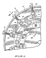
- Figure 1 is an end view partially cut away of the die face of a food cooker extruder showing a plurality of exit ports.
- Figure 2 is a sectional view greatly cut away of a reduction passageway in accordance with an embodiment of the present invention taken along lines 2-2 of Figure 1.
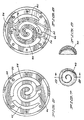
- Figure 3 shows an enlarged sectional view of a die insert for making an enlarged complexly shaped dough taken along lines 3-3 of Figure 2.
- Figure 4 is an enlarged sectional view of a die insert showing the channels for the food color flow taken along lines 4-4 of Figure 3.
- Figure 5 is an enlarged sectional view of the die insert taken along lines 5-5 of Figure 4 in an upstream orientation.
- Figure 6 is an enlarged sectional view of the die insert taken along lines 5-5 of Figure 4 similar to Figure 5 but showing a downstream orientation.
- Figure 7 is an enlarged plan view of a finished puffed complexly patterned R-T-E cereal piece prepared using the present methods and apparatus.
- Figure 8 is an enlarged sectional view of the R-T-E cereal piece taken along lines 8-8 of Figure 7 showing the concave shape of the cereal piece.
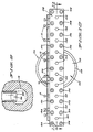
- Figure 9 is a partial sectional view of the food cooker extruder taken along lines 9-9 of Figure 2.
- Figure 10 is a front elevational view of a manifold for making multiple extrudates secured to the outlet of a food cooker extruder.
- Figure 11 is a partial cross-sectional view of the manifold taken along lines 11-11 of Figure 10.
- apparatus 10 generally includes a means for providing at least one extrudable food product or cooked cereal dough such as a cooker extruder 12 as seen in Figure 1.
- Extruder 12 is seen to have at least one, and more preferably a plurality of, exit ports or orifices 13 each for extruding of a complexly patterned cooked cereal dough of the present invention (not shown) or other extrudable food product.
- a cooker extruder is the preferred equipment to provide the extrudable food
- other conventional equipment and techniques can also be employed.
- a batch cooker or semi-continuous cooker for cooking the ingredients in bulk can be equipped with dough forming and conveying extruder element.
- a simple screw conveyor can be employed.
- the apparatus and techniques can be employed with a wide variety of extrudable food products, especially such plastic foods as low moisture fruit products.
- the cooker extruder 12 provides the cooked cereal dough in quantity which can supply one or preferably, especially in commercial applications, a plurality of passageways 14, each leading to an exit port 13.
- the apparatus 10 can additionally include a means for adjusting the cooked cereal dough flow rate and pressure such as the adjustably retractable dough flow adjuster plug 16 depicted.
- a flow rate adjustment means is particularly useful when, as in the embodiment depicted, the extruder supplies a large number of extrudate orifices. Absent such a flow rate adjustment means, the particular extrudate characteristics (e.g., pressure, mass flow) from each of so many orifices are difficult to control since the length of passageway 14 from the central supply can vary.
- Flow adjuster plug 16 can include a rod or bolt 80 having at least upper and lower cylindrical portions 84 and 86.
- Upper portion 84 in the most preferred form includes threads 82.
- Lower cylindrical portion 86 is in the most preferred form of a plug having a smooth outer periphery of a diameter which is less than the diameter of passageway 14.
- the inner axial end 88 of portion 86 opposite to portion 84 has a generally flat configuration and specifically has a diameter which is considerably larger than the diameter of passageway 14.
- Extruder 12 has a cylindrical bore which intersects generally perpendicular with passageway 14 and which includes a radially outward, threaded portion and a radially inward, smooth portion having a diameter generally equal to and for slideable and rotatable receipt of portion 86 such that the center line of portion 86 is generally perpendicular to the center line of passageway 14.
- Bolt 80 further includes a threaded portion located intermediate portions 84 and 86 of a size for threadable receipt in the extruder bore.
- Plug 16 further includes a means for sealing against dough of extruder 12 leaking from passageway 14 such as at least a first "O" ring 90, 91 inset into a receiving peripheral seal groove 92, 93, respectively.
- Plug 16 can further include lock nut 94 threaded on threads 82 of portion 84 and which can be tightened against block 96 to secure bolt 80 against movement such as caused by vibration of extruder 12.
- portion 86 By rotating bolt 80 into or out of the extruder bore, portion 86 can be adjustably retractably extended into passageway 14. It can then be appreciated that the area of flow through passageway 14 at plug 16 is inversely related to the extent that portion 86 extends into passageway 14. It should be appreciated that portion 86 can not choke or stop dough flow through passageway 14 or provide a buildup location for dough in passageway 14. In particular, due to the smaller diameter of portion 86 than passageway 14, the outer extent of portion 86 will extend along a chord of the circular cross section of passageway 14 at a spacing from its center less than its radius allowing flow of dough therebetween.
- portion 86 dough will tend to flow around portion 86 through passageway 14 and not stop in front thereof such as can occur if a flat or other non-cylindrical surface were presented.
- portion 86 is fully retracted out of passageway 14
- the extruder bore does not form locations outside of passageway 14 in which dough can accumulate.
- end 88 due to the preferred shape of end 88 relative to passageway 14, even if bolt 80 were rotated such that end 88 engaged the wall in extruder 12 defining passageway 14, end 88 does not closely mate passageway 14 but will similarly generally extend along a chord of the circular cross section of passageway 14 at a spacing from its center less than its radius allowing flow of dough therebetween.
- portion 86 covers less than 90% of the cross sectional area of passageway 14 allowing flow of dough through at least 10% of the cross sectional area of passageway 14 at all times.
- the apparatus 10 further essentially includes at least one food color supply 18 which can supply a flowable colored food material such as food color liquid (whether oil or preferably water based).
- the color supply 18 is in fluid communication with and the apparatus 10 further includes a means for mixing or forming the food color liquid and extrudable food product into a complexly patterned food extrudate such as a greatly enlarged (relative to the exit orifice) pattern forming die insert 20 depicted.
- the passageway 14 can include a first flared or divergent portion 21 immediately upstream of the die insert 20 to widen the passageway 14 to an equal diameter to the die insert 20 as well as a second convergent flared portion 22 downstream.
- the passageway 14 and other constituent elements are depicted in close to actual size.
- the diameter of the die insert 20 is about 30 mm and is positioned within a slightly enlarged portion 24 of passageway 14.
- the diameter of the complexly patterned dough extrudate as it exits the die insert 20 will have an enlarged initial diameter about 30 mm.
- other sizes for the die insert 20 can be used (e.g., 15 to 100 mm).
- the complexly patterned dough extrudate so formed then moves through by pressure flow and apparatus 10 further includes a means for reducing the cross sectional area of the complexly patterned food extrudate while maintaining the pattern such as a reducing or necking passageway 25 depicted.
- the reducing passageway 25 can be fabricated from a single piece having, for example, a frusto conical bore or, as depicted, with a plurality of individual pieces such as the first, second, and third pieces 26, 28 and 30, respectively, depicted. Individual pieces can be more easily cleaned.
- the convergence angle and other attributes can be adjusted as needed (e.g., smoothness, anti-stick surface) to accommodate differences in the extrudate characteristics of different food products.
- the passageway 14 has an initial relatively larger diameter 34 and a final relatively smaller or exit diameter 36 at the exit port 13.
- the passageway 14 can be fabricated with a more complex pattern or peripheral configuration to define or define in part the exterior shape or configuration of the finished piece, including both regular shapes (e.g., stars, rings, ovoids, geometric shapes) as well as irregular shapes (e.g., animals, objects such as trees, cars, etc.).
- the passageway 14 can be fabricated with an interior surface of desired characteristics, e.g., polished or Teflon or other non-sticking surface, such as to provide decreased friction to facilitate retention of the complex pattern or to reduce the pattern's deformation.
- desired characteristics e.g., polished or Teflon or other non-sticking surface, such as to provide decreased friction to facilitate retention of the complex pattern or to reduce the pattern's deformation.
- An important feature of the present invention is the convergence angle of the reducing passageway 25. It has been found important to maintain an average convergence or confinement angle of 5° to 45°, preferably 5° to 20°, and most preferably 10° to 15° in order to maintain the pattern while the cross sectional area is reduced.
- average convergence is meant the angle formed from the diameter of the die insert 20 to the diameter 36 of exit port 13 over the length of the reducing passageway 25.
- some pieces, e.g., 26 and 30 have a sharper convergence angle while piece 28 has a shallower angle.
- Internal obstructions e.g., shoulders
- Figure 2 shows that the exit orifice diameter 36 is about 3 mm. Since the passageway 14 can have a complex cross sectional shape as described above, the extent of reduction of the pattern is more aptly characterized in terms of cross sectional area reduction rather than more simply a reduction in diameter. Thus the degree of reduction of cross sectional area in the illustrated embodiment is about 100:1. Of course, for other embodiments (e.g., for larger snack pieces), the extent of cross section reduction can be as little as 25:1.
- the exit orifice diameter 36 for a snack product can be correspondingly larger, e.g., 5 to 15 mm.
- such a shallow convergence angle allows for a reduction in cross sectional areas of at least 50:1 and even about 100:1 while maintaining a fine level of detail in the complex pattern.
- a complex shape can be imparted to a larger dough face or cross section and then reduced to the much smaller desired finish cross sectional area.
- This arrangement allows for the fabrication of a relatively large die insert to impart the complex pattern. Fabricating a small die insert to impart the desired degree of detail for the final exit diameter while possible on a development scale extruder is not commercially practical due in part to plugging or fouling of the die insert 20.
- the provision of a reducing passageway 25 having the requisite convergence angle allows for the provision of three dimensional shapes to be produced with a fine level of color detail.
- the finished pieces are characterized by a color through the entire piece as compared to only topical coloration.
- Figure 3 shows an enlarged cross section of the pattern forming die insert 20.
- this particular die insert can be used to fabricate a bicolored food piece 40 as seen in Figure 7 having a swirl or spiral pattern.
- other pattern forming die inserts can be substituted therefor which, for example, can impart the line pattern for products reminiscent of soccer balls, basketballs, baseballs, and other sports objects.
- the die insert 20 includes a means for imparting at least one, and more desirably a plurality of, dough interstitial gaps such as between a plurality of dough dividing passageways such as passageways 44, 45, and 46 respectively formed by die dividing members 47.
- the die insert 20 can further include a means for injecting a food color or second colored dough into the interstitial dough gaps such as a plurality or array of evenly spaced food color injection ports 48 formed in die dividing members 47 and fed by a fluid supplying passageway 50 therethrough.
- the extrudable food product itself may be colored.
- the color supply 18 may supply a different color or the same color having a darker or lighter hue.
- the food color passageways 50 are supplied with the food liquid from one or more food color supply ports such as ports 52, 54, and 56, respectively in the die dividing members 47.
- the second or colored material is a food product such as a second dough or fruit paste
- the passageways and injection ports can be enlarged to reduce friction and the potential for blockage.
- the die insert 20 can further include a color fluid supply reservoir 58 supplied by the color supply 18 and which is in fluid communication with or supplies food color supply ports 52, 54, and 56.
- the die insert 20 can further include a means for sealing the color fluid supply reservoir 58 against premature admixture with dough such as "O" rings 60 and 62 depicted.
- Figure 5 shows the upstream face 64 of the die insert 22.
- Figure 5 shows that the upstream face 64 for this particular die insert contains no color supply discharge ports and that the discharge of color is preferably in a downstream direction.
- notches 57 The axial length of notches 57 is sufficient such that the dough extruded through passageways 44, 45, and 46 tends to flow into and fill the portions of the interstitial gaps in notches 57 upstream of where the color is discharged from ports 48. The portions of the interstitial gaps axially in line with notches 57 are then filled with dough upstream from where the color is discharged to prevent color added by ports 48 from flowing into those portions.
- notches 57 are shown formed in die dividing members 47 intermediate ports 48 and the interior surface wall and in the preferred form adjacent to the interior surface wall of die insert 20. If die dividing members 47 extend to and engage the interior surface wall of die insert 20, color will tend to travel in the interstitial gaps all the way to the interior surface wall of die insert 20 and will tend to fill the void between the dough passing through passageways 44, 45, and 46 and the interior surface wall of die insert 20. This leads to a disproportionate amount of color being on the outside of the extruded dough. Thus, notches 57 generally prevent color from traveling all the way to the interior surface wall of die insert 20 to practically eliminate or reduce the color on the outside of the extruded dough.
- notches 57 can also be provided in die dividing members 47 spaced from the interior surface wall of die insert 20.
- One reason for such an arrangement would be where multiple colors are desired in the extruded dough. This can be accomplished by supplying a first color to certain of the ports 48 with the other ports 48 being supplied with a different color(s) or hue(s). Notches 57 can then be provided in die dividing members 47 separating those certain ports 48 from the other ports 48 to generally prevent intermixing of the additives in the extruded dough.
- FIGS 7 and 8 show that the food piece 40 can have a cupped shape and that the coloration can extend throughout the body of the piece.
- the piece 40 depicted is a puffed R-T-E cereal piece prepared by direct expansion from the extruder having a finished diameter of about 70 mm.
- the complexly patterned dough of reduced cross sectional diameter is extruded through the reduced diameter exit orifice 36 (e.g., about 3 mm). Thereafter, the extrudate is face cut in a conventional manner to form individual pieces such as with one or more rotating knives.
- an unpuffed pellet piece can be formed for subsequent puffing, or, alternatively, and preferably herein, a directly expanded finished puffed piece is formed.
- the finished food piece whether subsequently puffed or puffed by direct expansion upon exiting the exit orifice 13 is essentially characterized by exhibiting a high resolution or fine degree of color detail. The detail can include surface line coloration of as thin as about 0.5 mm in the puffed product.
- the interior is also bicolored or multicolored as well as having topical or surface coloration.
- the extrudable food can comprise a wide variety of conventional food types and in particular can include a fruit paste, potato dough (e.g., for a fabricated chip) or a cooked cereal dough.
- the cooked cereal dough can be for either R-T-E cereals (whether puffed or unpuffed), snack products, baked goods, or pastas.
- cooked cereal doughs for puffed R-T-E cereals Puffed food products such as snacks can be prepared by hot air puffing, deep fat frying, gun puffing or microwave (especially high intensity, e.g., >100 V/cm field strength).
- Product puffed without deep fat frying can have oil added to the composition or have a topical oil application.
- R-T-E cereals can have a sugar coating.
- Puffed food pieces of the product base can have a density of about 0.1 to 0.5g/cc.
- the colored portion forms a line or a plane through the body of the food piece.
- "Highly complex" food products are characterized as having a plurality of colored features at least two of which (e.g., two planes or a line and a plane) intersect within the body of the food piece.
- the particular die insert 20 depicted is designed to admix a liquid food color into a cooked cereal dough so as to provide line coloration of extremely fine detail
- the die insert 20 can be modified (e.g., such as by enlargement of ports 52, 54, and 56, fluid passageways 50, and discharge ports 48) to admix two or more cooked doughs or other flowable colored food materials, especially liquefied fats (e.g., chocolate, cheese), or fruit paste.
- die insert 20 depicted is designed to provide the swirled finished product depicted
- other die inserts can be interchanged to provide the line coloration detail to provide the particular desired end products such as the various sports balls (e.g., soccer, baseball, basketball, American football) referenced above.
- various sports balls e.g., soccer, baseball, basketball, American football
- manifold 100 includes body portions 102, 104, 106 and 108 which are secured together into a unitary assembly.
- body portion 102 includes a circular disc 110 which abuts with the mounting flange 112 of the outlet of food cooker extruder 12.
- Disc 110 can be secured to extruder 12 by any conventional means and in the preferred form includes an annular lip 114 formed on its outer periphery at the inner axial end which abuts with flange 112, with lip 114 being of a size and shape generally corresponding to flange 112.
- Bores or conduit portions 118 intersect at the inner axial end of disc 110 at the center line of extruder 12 and disc 110 and extend therefrom at equal acute angles on opposite sides of the center line of extruder 12 and disc 110 in the order of 62° in the most preferred form, with the center lines of bores 118 and the center line of extruder 12 and disc 110 being arranged in a horizontal plane in the most preferred form.
- Body portion 102 further includes first and second pipes or conduit portions 116 which extend linearly from bores 118 formed in disc 110 past the outer axial end of disc 110 to equal distances from disc 110.
- Body portion 102 further includes first and second conduit portions 120 located on opposite sides, parallel to, and at equal distances from the center line of extruder 12 and disc 110, with the center lines of conduit portions 120, extruder 12 and disc 110 being arranged in a horizontal plane in the most preferred form.
- Conduit portions 120 have cross sections of an equal size and shape to pipes 116.
- the outer axial ends of first and second pipes 116 opposite to disc 110 are integrally connected to and in fluid communication with the inner axial ends of first and second conduit portions 120, respectively, in the most preferred form by a mitered interconnection.
- the outer axial ends of conduit portions 120 are equally spaced from disc 110 and extruder 12.
- Body portion 102 further includes a flat mounting plate 122 which is held generally perpendicular to the center lines of conduit portions 120, extruder 12 and disc 110 by a support 124 extending between and integrally connected to the outer axial end of disc 110 and the inner axial end of plate 122.
- Conduit portions 120 extend through suitable bores formed in mounting plate 122 and are integrally secured to mounting plate 122.
- the outer axial end of mounting plate 122 is perpendicular to the center lines of conduit portions 120, disc 110, and extruder 12 and is at the same axial extent from disc 110 and extruder 12 as the outer axial ends of conduit portions 120.
- Body portion 104 is in the most preferred form of a block having an inner axial end which abuts with mounting plate 122. Body portion 104 is symmetrical on opposite sides of the center line of disc 110 and extruder 12 according to preferred teachings of the present invention.
- body portion 104 includes first and second conical chambers 126 having center lines which are linear with the center lines of conduit portions 120. The bases of chambers 126 are located at the inner axial end of body portion 104 and have a diameter equal to the inner diameter of conduit portions 120.
- First and second passageway portions 128 of equal size and diameter extend from each of chambers 126 at equal acute angles on opposite sides of the center line of chamber 126 and conduit portion 120 in the order of 49° in the most preferred form, with the center lines of passageway portions 128, chambers 126, conduit portions 120, bores 118, pipes 116 and extruder 12 being arranged in a horizontal plane in the most preferred form.
- Body portion 104 further includes third and fourth passageway portions 130 in fluid communication with first and second passageways 128, respectively, and located on opposite sides, parallel to and at equal distances from the center lines of the first and second chambers 126 and conduit portions 120, respectively, with the center lines of passageway portions 128 and 130 being in a horizontal plane in the most preferred form.
- Passageway portions 128 and 130 have cross sections of an equal size and shape and in the most preferred form have diameters which are approximately 57% of the diameter of conduit portions 116, 118, and 120.
- Body portion 104 further includes first and second duct portions 132 having center lines which are coextensive with the center lines of the first and second chambers 126 and conduit portions 120, respectively, with duct portions 132 extending from chambers 126 concentric to the center line of chambers 126 and opposite to their bases.
- duct portions 132 have a cross-sectional shape corresponding to passageway portions 128 and 130 which is circular in the most preferred form but have a size which is smaller than passageway portions 128 and 130 and in the most preferred form have diameters equal to approximately 65% of the diameter of passageway portions 128 and 130.
- duct portions 132 have a size which do not intersect with passageway portions 128 at chamber 126, with duct portions 132 having a diameter equal to the diameter of chambers 126 equal to the outer axial extent of passageway portions 128 at the surfaces of chambers 126 in the most preferred form.
- Body portion 106 is in the most preferred form of a block having an inner axial end which abuts with the outer axial end of body portion 104.
- Body portion 106 is symmetrical on opposite sides of the center line of disc 110 and extruder 12 according to the preferred teachings of the present invention.
- first and second ports 134 of equal size and diameter extend from the first passageway portions 130 extending from first and second chambers 126 at equal acute angles on opposite sides of the center line of first passageway portion 130 in the order of 43° in the most preferred form, with the center lines of ports 134 and passageway portions 130 being arranged in a horizontal plane in the most preferred form.
- third and fourth ports 136 of equal size and diameter extend from the second passageway portion 130 extending from first and second chambers 126 at equal acute angles on opposite sides of the center line of second passageway portion 130 in the order of 43° in the most preferred form, with the center lines of ports 136 and passageway portions 130 being arranged in a horizontal plane in the most preferred form.
- Ports 134 and 136 have equal lengths.
- Body portion 106 further includes first and second duct portions 138 having center lines which are coextensive with the center lines of first and second duct portions 132 and chambers 126 of body portion 104 and of conduit portions 120, respectively.
- Duct portions 138 have a cross sectional size and shape corresponding to duct portions 132.
- Ports 134 and 136 have the same cross sectional size and shape which in the preferred form also are equal to the cross sectional size and shape of duct portions 132 and 138.
- Body portion 106 then includes a plurality of flow adjuster plugs 16 of a number corresponding to the total number of ports 134 and 136 and duct portions 138 formed therein and mounted to the upper surface thereof.
- plugs 16 are mounted such that smooth portion 86 can be adjustably extended into the corresponding port 134 or 136 or duct portion 138 to adjust the flow rate and pressure of the dough flow therethrough.
- Body portion 108 is in the host preferred form of a block having an inner axial end which abuts with the outer axial end of body portion 106.
- Body portion 108 is symmetrical on opposite axial sides of the center line of disc 110 and extruder 12 according to the preferred teachings of the present invention.
- sockets 140 equal in number and location to ports 134 and 136 and duct portion 138 are provided for slideable receipt of the desired inserts 142.
- inserts 142 can be of the type including die inserts 20 and passageway pieces 26, 28, and 30 or can be of alternate types and forms.
- Body portions 102, 104, 106, 108 can then be suitably secured together such as by bolts 144 extending through body portions 108 and 106 and threaded into body portion 104 and by bolts 146 extending through body portions 108, 106, and 104 and threaded into nounting plate 122.
- dowel pins 148, 150, and 152 can be provided between body portions 108 and 106, body portions 106 and 104, and body portion 104 and mounting plate 122, respectively.
- dough extruded by extruder 12 will flow through flow paths at equal rates and pressure through conduits 116, 118, and 120 into chamber 126 since they provide the same resistance to flow due to their equal lengths, cross sectional sizes and shapes, and arrangement much like through passageways 14.
- dough will flow through passageways 128 and 130 from chambers 126 at equal rates and pressure since they provide the same resistance to flow due to their equal lengths, cross sectional size and shape, and arrangement.
- dough will flow through ports 134 and 136 from passageways 128 and 130 at equal rates and pressure since they provide the same resistance to flow due to their equal lengths, cross sectional size and shape, and arrangement.
- ducts 132 and 138 have a smaller cross sectional size than passageways 128 and 130, the flow rate of dough through a single duct 132 and 138 is one-half the flow rate through one of ports 134 and 136.
- the cross sectional size is reduced to a size to provide equal flow resistance therethrough as through dough flowing through one of the ports 134 and 136.
- the cross sectional size of ports 134 and 136 and ducts 132 and 138 are equal for ease of fabrication and to allow the same size adjuster plugs 16 to be utilized in all of the ports 134 and 136 and duct portions 138.
- the flow rate and pressure from extruder 12 to inserts 142 are equal even though the flow distances from extruder 12 to inserts 142 are not equal according to the illustrated embodiment.
- the flow rate and pressure to inserts 142 are generally compensated by providing unequal flow areas to effect equalizing flow resistance and are fine tuned through the use of adjuster plugs 16 according to the preferred teachings of the present invention.
- notches 57 prevent colorant, flavor or other additives from coming in contact with the interior surface wall of the insert where the static mixer has difficulty mixing it thoroughly with the main flow of product. This would allow the static mixer to be shorter and still provide a uniform extrudate and thus reducing the cost, space and pressure drop requirements of the static mixer.
Landscapes
- Engineering & Computer Science (AREA)
- Food Science & Technology (AREA)
- Life Sciences & Earth Sciences (AREA)
- Confectionery (AREA)
- Formation And Processing Of Food Products (AREA)
- Extrusion Moulding Of Plastics Or The Like (AREA)
- Manufacturing And Processing Devices For Dough (AREA)
- General Preparation And Processing Of Foods (AREA)
- Grain Derivatives (AREA)
- Meat, Egg Or Seafood Products (AREA)
- Bakery Products And Manufacturing Methods Therefor (AREA)
- Manufacturing Of Printed Wiring (AREA)
- Internal Circuitry In Semiconductor Integrated Circuit Devices (AREA)
- Manufacturing Of Electric Cables (AREA)
- Noodles (AREA)
- Treatments Of Macromolecular Shaped Articles (AREA)
Abstract
Description
Claims (46)
- An apparatus (10) for making a complexly patterned flowable extrudate including means (12) for providing a first extrudable food material, means (18) for supplying a second flowable colored food material, means (20) for forming the first extrudable food material and the second flowable colored food material into a patterned food mass having an initial cross sectional area, reducing passageway means (25) for reducing the initial cross sectional area to a reduced cross sectional area and operatively connected to the pattern forming means and having a larger inlet end and a smaller outlet end, and an extrudate exit port (13) having a diameter of about the reduced cross sectional area proximate the outlet end characterized in that the reducing passageway means (25) reduces the cross sectional area of the patterned food mass by at least 25:1 and has an average convergence angle ranging from about 5° to 45° to produce the complexly patterned flowable extrudate.
- The apparatus of claim 1 wherein the means (12) for providing the first extrudable food material includes at least one extrudate passageway (14) each having an initial cross sectional area, wherein the means for forming a patterned food mass includes an enlarged die insert (20) having an enlarged cross section relative to the cross section of the exit port (13) within an enlarged portion of the extrudate passageway (14) having a die insert diameter (21) and cross sectional area and wherein the ratio of the die insert cross section area to the reduced cross sectional area ranges from 25 to 100:1.
- The apparatus of claim 2 wherein the die insert (20) includes at least one food product dividing member (47) having a passageway therethrough (50) in fluid communication with the second colored food material supply means (18) and a plurality of second colored food material supply discharge holes (48).
- The apparatus of claim 3 wherein the second colored food material supply discharge holes (48) are evenly spaced and are in the downstream face of the die insert (20).
- The apparatus of any preceding claim wherein the reducing passageway means (25) is defined by a plurality of pieces having differing convergence angles.
- The apparatus of claim 5 wherein each passageway piece has a cross section equal to the upstream cross section of the next downstream piece so as to form a continuously smooth passageway.
- The apparatus of any preceding claim wherein at least a portion of the reducing passageway means (25) has a circular cross section.
- The apparatus of any preceding claim wherein at least a portion of the reducing passageway means (25) has an irregularly shaped periphery.
- The apparatus of claim 8 wherein at least a portion of the reducing passageway means (25) has an oval cross section.
- The apparatus of any preceding claim wherein the means (12) for providing a first extrudable food material additionally comprises a means (16) for externally adjusting the dough flow rate upstream of the forming means (20).
- The apparatus of claim 10 wherein the means (16) for externally adjusting the dough flow rate includes a rounded smooth retractably adjustable plug (16) projecting into the passageway (14); means (80, 82) for adjustably retractably extending the plug (16) into the passageway (14) including stop means exterior to the passageway (14) for terminating the extension of the plug (16) into the passageway (14); wherein the length of the plug (16) extending into the passageway (14) when stopped by the stop means is less than 90% of the width of the passageway (14); and means (90-93) for sealing the plug (16) against food leakage.
- The apparatus of claim 11 wherein the means for adjustably retractably extending the plug (16) includes a bore in the means (12) for providing a first extrudable food material, said bore intersecting with the extrudate passageway (14) at a downstream angle of 90°> and having an outward threaded portion and an inward smooth portion, and wherein the plug (16) has an outward portion (84) having threads (82) and an inward smooth portion (86).
- The apparatus of claim 12 wherein the means for adjustably retractably extending the plug (16) further comprises, in combination: a lock nut (94) threaded on the outward portion (84) of the plug (16) and which can be tightened to secure the plug (16) against movement such as caused by vibration.
- The apparatus of any of claims 10 to 13, wherein the extrudate passageway (14) has a circular cross section and a center line, and the plug (16) has a circular cross section of a diameter less than the cross section of the extrudate passageway (14) and a center line, with the center line of the extrudate passageway (14) being at a non-parallel angle to the center line of the plug (16), with the plug (16) having an axial end (88) located inside of the extrudate passageway (14), characterized in the axial end (88) of the plug (16) having a configuration which can not mate with the extrudate passageway (14) allowing flow of dough between the axial end (88) of the plug (16) and the extrudate passageway (14) at all positions of the plug (16).
- The apparatus of claim 14 wherein the configuration of the axial end (88) of the plug (16) has a diameter which is considerably larger than the diameter of the extrudate passageway (14).
- The apparatus of claim 3 wherein the food product dividing member (47) imparts at least one interstitial gap, with the dividing member (47) including an upstream face and a downstream face; wherein the second colored food material supply discharge holes (48) supply the second colored food material at the downstream face and into the interstitial gap, with the second colored food material travelling in the interstitial gap; and wherein the apparatus further comprises, in combination: a notch (57) formed in the dividing member (47) extending from the downstream face towards but spaced from the upstream face and having an axial length sufficient for the first extrudable food material to flow into and fill the interstitial gap within the notch (57).
- The apparatus of claim 16 wherein the die insert (20) further includes an interior surface wall, with the food product dividing member (47) extending to and engaging the interior surface wall, with the notch (57) located in the food product dividing member (47) intermediate the second food material supply discharge holes (48) and the interior surface wall.
- The apparatus of claim 17 wherein the notch (57) is formed adjacent to the interior surface wall.
- The apparatus of any one of claims 16 to 18 wherein the dividing member (47) divides the flowing dough into at least first and second passageways (44, 45, 46).
- The apparatus of any preceding claim wherein the first extrudable food material is the product base for puffed food products.
- The apparatus of any preceding claim, including a plurality of exit orifices located at differing spacings from said means (12) for providing a first extrudable food material; and with each of the exit orifices including a flow path for the food dough from the means (12) for providing a first extrudable food material to the exit orifice, a said pattern forming means (20) and a said reducing passageway means (25) being formed in each of said flow paths, with the flow paths of at least two pair of the exit orifices being formed by at least first and second passageways (128) and first, second, third, and fourth ports (134), with the first and second passageways (128) extending downstream from an interconnection (126) at a passageway angle relative to each other and having equal cross sectional sizes and shapes, with the first and second ports (134) extending downstream from the first passageway (128) and having generally equal cross sectional sizes and shapes and the third and fourth ports (134) extending downstream from the second passageway (128) and having generally equal cross sectional sizes and shapes generally equal to the cross sectional sizes and shapes of the first and second ports (134) and less than the cross sectional sizes of the first and second passageways (128), with the first and second passageways (128) having generally equal lengths, with the first, second, third, and fourth ports (134) having generally equal lengths, wherein the flow path of at least one of the exit orifices is formed by a duct (132) having a constant size from the interconnection (126) of the first and second passageways (128) to the exit orifice, with the cross sectional size of the duct (132) being less than the cross sectional size of the first and second passageways (128).
- The apparatus of claim 21 wherein the flow paths each include means (16) for adjusting the rate and pressure of the flow of the dough.
- The apparatus of claim 21 or 22 wherein the duct (132) has a cross sectional size and shape generally equal to the cross sectional size and shape of the first, second, third, and fourth ports (134).
- The apparatus of any of claims 21 to 23 wherein the interconnection (126) between the first and second passageways (128) comprises a conical chamber having a base and a center line, with the first and second passageways (128) extending from the conical chamber at nonparallel equal angles on opposite sides of the center line of the conical chamber, with the duct (132) extending from the conical chamber concentric to the center line and opposite to the base.
- The apparatus of any of claims 21 to 24 wherein the first and second ports (134) extend at a port angle on opposite sides of the first passageway (128) and the third and fourth ports (134) extend at the port angle on opposite sides of the second passageway (128).
- The apparatus of any of claims 21 to 25 wherein the plurality of exit orifices are located in a single, horizontal plane.
- The apparatus of any of claims 21 to 26 wherein the flow paths further comprise, in combination: first and second conduits (116) extending at an angle relative to each other and having generally equal cross sectional sizes and shapes and greater than the cross sectional sizes of the first and second passageways (128), with the first and second conduits (116) having generally equal lengths, with the first and second passageways (128) extending from the first conduit (116); third and fourth passageways (128) extending from the second conduit (116); and fifth, sixth, seventh, and eighth ports (134), with the fifth and sixth ports (134) extending from the third passageway (128) and the seventh and eighth ports (134) extending from the fourth passageway (128).
- The apparatus of claim 27 wherein the means (12) for providing a first extrudable food material comprises an outlet including an annular mounting flange (112); and wherein the apparatus further comprises a disc (110) for abutting with and securement to the annular mounting flange (112), with the first and second conduits (116) extending from bores (118) formed in the disc (110), with the bores (118) being in communication with the means (12) for providing a first extrudable food material.
- The apparatus of claim 28 further comprising, in combination: a mounting plate (122) supported by the disc (110), with the conduits (116) extending into and through the mounting plate (122); and a manifold block secured to the mounting plate (122), with the passageways (128) and ports (134) formed in the manifold block.
- A puffed food piece having a body of one color and at least two intersecting colored lines or planes of at least a second color or hue extending through the body.
- The puffed food piece of claim 30 wherein the colored lines have a thickness of 1 mm>.
- The food piece of claim 30 or 31 wherein the two intersecting colored lines or planes are of the second and a third color or hue.
- The food piece of any claim 30 to 32 having a spherical shape with a plurality of lines forming a shape of a soccer ball, a baseball, and American style football.
- The food piece of any claim 30 to 33 having a diameter of about 15 to 30 mm.
- A method for preparing a food product having at least two colors exhibiting improved detail resolution including the steps of:A. providing a first plastic extrudable food mass having a first color;B. providing at least a second flowable food material having a second color differing from the first color in color or hue;C. mixing the food mass and the second food material to form a patterned food mass having an initial cross sectional area;D. reducing the cross sectional area of the patterned food mass through a reducing passageway (25) while maintaining the cross sectional pattern to form a reduced cross sectional patterned extrudate; andE. extruding the reduced cross sectional extrudate through a die port (13) characterized in that the reducing step comprises reducing the food mass by a factor of at least 4:1 and with the reducing passageway (25) having an average convergence angle of 5° to 45° to produce the food product exhibiting fine detail resolution between at least two colors.
- The method of claim 35 wherein the initial cross section of the first food mass is about 1200 to 3000 mm2 and wherein the reduced cross sectional area is about 10 to 300 mm2
- The method of claim 35 or 36 wherein the food and color are mixed in a passageway (14) of a cooker extruder (12) with a die dividing insert (20) therein and wherein the reducing passageway (25) is continuous.
- The method of any claim 35 to 37 wherein the first food mass comprises a cooked cereal dough.
- The method of any claim 35 to 38 wherein the cross sectional area is reduced in a converging frusto conically shaped passageway (25).
- The method of any claim 35 to 39 wherein the extrudate is directly expanded upon and cut to form individual pieces of puffed cereal dough.
- The method of any claim 35 to 39 wherein the extrudate is extruded to form an unexpanded complexly patterned dough of reduced cross sectional area; and wherein the method additionally comprises the steps of:F. sectioning the extruded complexly patterned dough. to form individual half product or pellet pieces having a complex pattern; andG. puffing the pieces to form puffed food pieces.
- The method of claim 41 wherein the puffed food pieces have a spherical shape.
- The method of any claim 35 to 42 wherein the mixing step comprises the steps of: dividing the food mass to impart at least one interstitial gap in the food mass; partially filling the interstitial gap with the food mass; and injecting the second flowable food material at a location downstream of where the interstitial gap is partially filled in remaining portions of the interstitial gap.
- The method of claim 43 wherein the step of dividing the food mass comprises the step of providing a die dividing member (47) including an upstream face and a downstream face; wherein the partially filling step comprises the step of notching the die dividing member (47) from the downstream face towards but spaced from the upstream face and having an axial length sufficient for the food mass to flow into and fill the interstitial gap within the notch (57); and wherein the injecting step comprises the step of injecting the second flowable food material at the downstream face and into the interstitial gap, with the second flowable food material travelling in the interstitial gap.
- The method of claim 44 wherein the providing step comprises the step of providing the die dividing member (47) extending to and engaging an interior surface wall of an insert (20), with the flowing dough flowing through the interior surface; and wherein the notching step comprises the step of notching (57) the die dividing member (47) intermediate the location at which the additive is injected and the interior surface wall.
- The method of any one of claims 35 to 45 wherein the dividing step comprises the step of dividing the flowing dough into at least first and second passageways (44, 45, 46).
Priority Applications (2)
| Application Number | Priority Date | Filing Date | Title |
|---|---|---|---|
| EP02006159A EP1221284B1 (en) | 1994-05-11 | 1995-05-10 | Food piece and apparatus and methods for making multiple, complexly patterned extrudates |
| EP01203224A EP1166634A3 (en) | 1994-05-11 | 1995-05-10 | Apparatus and methods for making multiple, complexly patterned extrudates |
Applications Claiming Priority (5)
| Application Number | Priority Date | Filing Date | Title |
|---|---|---|---|
| US241321 | 1994-05-11 | ||
| US08/241,321 US5639485A (en) | 1994-05-11 | 1994-05-11 | Apparatus for making a complexly patterned extrudate |
| US08/353,477 US5643618A (en) | 1994-05-11 | 1994-12-09 | Apparatus for making multiple, complexly patterned extrudates |
| US353477 | 1994-12-09 | ||
| PCT/US1995/005553 WO1995031108A1 (en) | 1994-05-11 | 1995-05-10 | Apparatus and methods for making multiple, complexly patterned extrudates |
Related Child Applications (2)
| Application Number | Title | Priority Date | Filing Date |
|---|---|---|---|
| EP02006159A Division EP1221284B1 (en) | 1994-05-11 | 1995-05-10 | Food piece and apparatus and methods for making multiple, complexly patterned extrudates |
| EP01203224A Division EP1166634A3 (en) | 1994-05-11 | 1995-05-10 | Apparatus and methods for making multiple, complexly patterned extrudates |
Publications (2)
| Publication Number | Publication Date |
|---|---|
| EP0760604A1 EP0760604A1 (en) | 1997-03-12 |
| EP0760604B1 true EP0760604B1 (en) | 2002-03-20 |
Family
ID=26934191
Family Applications (3)
| Application Number | Title | Priority Date | Filing Date |
|---|---|---|---|
| EP01203224A Withdrawn EP1166634A3 (en) | 1994-05-11 | 1995-05-10 | Apparatus and methods for making multiple, complexly patterned extrudates |
| EP95918381A Expired - Lifetime EP0760604B1 (en) | 1994-05-11 | 1995-05-10 | Apparatus and method for making multiple, complexly patterned extrudates |
| EP02006159A Expired - Lifetime EP1221284B1 (en) | 1994-05-11 | 1995-05-10 | Food piece and apparatus and methods for making multiple, complexly patterned extrudates |
Family Applications Before (1)
| Application Number | Title | Priority Date | Filing Date |
|---|---|---|---|
| EP01203224A Withdrawn EP1166634A3 (en) | 1994-05-11 | 1995-05-10 | Apparatus and methods for making multiple, complexly patterned extrudates |
Family Applications After (1)
| Application Number | Title | Priority Date | Filing Date |
|---|---|---|---|
| EP02006159A Expired - Lifetime EP1221284B1 (en) | 1994-05-11 | 1995-05-10 | Food piece and apparatus and methods for making multiple, complexly patterned extrudates |
Country Status (12)
| Country | Link |
|---|---|
| US (2) | US5643618A (en) |
| EP (3) | EP1166634A3 (en) |
| CN (1) | CN1152855A (en) |
| AT (2) | ATE300180T1 (en) |
| AU (1) | AU707616B2 (en) |
| CA (1) | CA2192684C (en) |
| DE (2) | DE69525942T2 (en) |
| DK (1) | DK0760604T3 (en) |
| ES (2) | ES2173184T3 (en) |
| HK (1) | HK1047522B (en) |
| PT (2) | PT1221284E (en) |
| WO (1) | WO1995031108A1 (en) |
Families Citing this family (52)
| Publication number | Priority date | Publication date | Assignee | Title |
|---|---|---|---|---|
| US5626892A (en) * | 1993-11-24 | 1997-05-06 | Nabisco, Inc. | Method for production of multi-flavored and multi-colored chewing gum |
| US5639485A (en) * | 1994-05-11 | 1997-06-17 | General Mills, Inc. | Apparatus for making a complexly patterned extrudate |
| US5643618A (en) * | 1994-05-11 | 1997-07-01 | General Mills, Inc. | Apparatus for making multiple, complexly patterned extrudates |
| US5620713A (en) * | 1995-06-06 | 1997-04-15 | The Pillsbury Company | Extrusion die for dough |
| US5686128A (en) * | 1995-08-31 | 1997-11-11 | Nabisco Technology Company | Apparatus and method for triple co-extruding a snack product |
| US5843503A (en) * | 1997-02-24 | 1998-12-01 | General Mills, Inc. | Apparatus and method for making multiple patterned extrudates |
| US5919509A (en) * | 1997-05-01 | 1999-07-06 | General Mills, Inc. | Method and apparatus for producing multiple food extrudates |
| US5965186A (en) * | 1997-09-24 | 1999-10-12 | The Pillsbury Company | Crisp dough structure and method for imparting crispness to dough |
| US6340123B1 (en) | 1997-10-31 | 2002-01-22 | Ching-Chin Lee | Universal flow channel |
| US6251452B1 (en) | 1999-04-23 | 2001-06-26 | General Mills, Inc. | Apparatus and methods for making multiple, complexly patterned extrudates |
| US6258392B1 (en) | 1999-10-05 | 2001-07-10 | Celsi Giampietro | Microwaveable pasta pie and pan assembly |
| US6509049B1 (en) | 2000-06-16 | 2003-01-21 | The Quaker Oats Company | Device system and method for fluid additive injection into a viscous fluid food stream |
| US6932591B2 (en) * | 2001-06-28 | 2005-08-23 | Primex Plastics Corporation | Apparatus and method for co-extruding multi color plastics |
| US6620448B2 (en) * | 2001-10-29 | 2003-09-16 | Recot, Inc. | Extruder die with additive reservoir |
| US7585532B2 (en) * | 2001-10-29 | 2009-09-08 | Frito-Lay North America, Inc. | Apparatus and method for improving the dimensional quality of extruded food products having complex shapes |
| US6854970B2 (en) | 2001-10-29 | 2005-02-15 | Frito-Lay North America, Inc. | Extruder die injection nozzle |
| US7252847B2 (en) * | 2001-10-29 | 2007-08-07 | Frito-Lay North America, Inc. | Flavored extruded food product |
| US7648352B2 (en) * | 2001-10-29 | 2010-01-19 | Frito-Lay North America, Inc. | Apparatus for imprinting lines on direct-expanded food products having complex shapes with improved dimensional quality |
| ES2221522B1 (en) * | 2002-05-08 | 2006-01-16 | Diseño Tecnologico Avanzado Del Molde, S.L. | MACHINE TO EXTRUSION SWEETS OR SIMILAR. |
| WO2004004486A1 (en) * | 2002-07-03 | 2004-01-15 | Unilever N.V. | Pasta compostions |
| EP1662891A2 (en) * | 2003-09-19 | 2006-06-07 | Kellogg Company W.K. Kellogg Institute | Multi-piece food product and method for making the same |
| USD526762S1 (en) | 2003-12-22 | 2006-08-22 | Kellogg Company | Multi-piece fruit snack |
| CA2505186C (en) * | 2004-04-26 | 2012-08-21 | General Mills Ip Holdings Ii, Llc | Low sugar presweetened coated cereals and method of preparation |
| US8119174B2 (en) | 2004-04-26 | 2012-02-21 | General Mills Ip Holdings Ii, Llc | Low sugar presweetened dry coated cereals and method of preparation |
| US20110014311A1 (en) * | 2005-09-20 | 2011-01-20 | Holmes Terry L | Method and system for making extruded portions of cheese |
| US8377490B2 (en) * | 2005-09-20 | 2013-02-19 | Kraft Foods Global Brands Llc | Method and system for making sliced cheese |
| US20070237881A1 (en) * | 2006-04-05 | 2007-10-11 | Annette Marques | Rainbow cake - process of creating rainbow effect |
| CA2723491A1 (en) * | 2008-05-06 | 2009-11-12 | Kerry, Inc. | Extrusion die with extrusion port having a shaped extrusion outlet |
| US8071149B2 (en) | 2008-08-07 | 2011-12-06 | Amf Automation Technologies, Inc. | Easy open dough distribution manifold |
| US20100123262A1 (en) * | 2008-11-18 | 2010-05-20 | Lewis Conrad Keller | Multi-orifice extrusion die and method for obtaining uniform flow |
| US7611347B1 (en) * | 2009-04-08 | 2009-11-03 | Wenger Manufacturing Inc. | Extrusion die assembly for high density products |
| US8197243B2 (en) * | 2009-07-28 | 2012-06-12 | American Extrusion International | Head assembly for use in a rotary head extruder for extruding a food product |
| GB201003288D0 (en) * | 2010-02-26 | 2010-04-14 | Cadbury Uk Ltd | Apparatus and method for manufacturing products |
| US8287262B2 (en) | 2010-04-12 | 2012-10-16 | General Mills, Inc. | Methods and apparatus for producing multiple food extrudates |
| US9277753B2 (en) | 2010-08-20 | 2016-03-08 | Frito-Lay North America, Inc. | Synchronized cutting and injection system and method |
| US20120152224A1 (en) * | 2010-12-15 | 2012-06-21 | General Electric Company | Venting system for cooking appliance |
| US20120171337A1 (en) * | 2011-01-05 | 2012-07-05 | AMF Automation Technologies, LLC d/b/a AMF Bakery Systems | Dough Portioner |
| US8287268B1 (en) | 2011-04-15 | 2012-10-16 | Thomas Michael R | Distiller grain pellet production devices |
| CA3065598C (en) | 2011-07-28 | 2022-06-07 | Societe Des Produits Nestle S.A. | Methods and devices for heating or cooling viscous materials |
| US10499681B2 (en) | 2011-09-21 | 2019-12-10 | General Mills, Inc. | Coated food product and methods |
| WO2016151064A1 (en) * | 2015-03-26 | 2016-09-29 | Nestec S.A. | A forming die for a wet extrusion process |
| US9572555B1 (en) * | 2015-09-24 | 2017-02-21 | Ethicon, Inc. | Spray or drip tips having multiple outlet channels |
| CN106818978B (en) * | 2017-03-29 | 2022-09-02 | 曹壬圣 | Pattern machine |
| CN107319570A (en) * | 2017-07-21 | 2017-11-07 | 贵州省贝真食业有限公司 | A kind of plain meat molding die |
| IT201700115792A1 (en) * | 2017-10-13 | 2019-04-13 | Atlantic Man S R L | ALGA EXTRUSION DRAWER AND ITS EXTRUDER |
| US11173645B2 (en) * | 2018-04-09 | 2021-11-16 | The Boeing Company | Apparatuses and methods for applying radius filler |
| US20190387784A1 (en) * | 2018-04-13 | 2019-12-26 | Zongen Li | Electromagnetically tightening & losing, electromagnetically cutting and second eatable-stuff input puffing machine |
| PL4015189T3 (en) * | 2020-12-21 | 2024-01-03 | Vkr Holding A/S | A stack die for extrusion moulding comprising improved die elements, method of manufacturing the stack die and use thereof to provide an extruded article |
| EP4059357A1 (en) * | 2021-03-15 | 2022-09-21 | Bühler AG | Extruder distributing device |
| CN112931555B (en) * | 2021-03-18 | 2022-07-19 | 中国农业科学院农产品加工研究所 | Wheaten food processing equipment |
| DE102021109440A1 (en) | 2021-04-15 | 2022-10-20 | Louise Dobslaff | Dry crisp and plant-based food product |
| GB202406183D0 (en) * | 2024-05-02 | 2024-06-19 | Baker Perkins Ltd | Tube-filled product formed by co-extrusion |
Family Cites Families (101)
| Publication number | Priority date | Publication date | Assignee | Title |
|---|---|---|---|---|
| US518942A (en) * | 1894-05-01 | dtjhrkop | ||
| US14068A (en) | 1856-01-08 | savage | ||
| US14233A (en) | 1856-02-12 | gallaher | ||
| US14474A (en) | 1856-03-18 | Nail-plate-feediug- hachiite | ||
| US14069A (en) | 1856-01-08 | Method of preventing bank-notes | ||
| US449854A (en) * | 1891-04-07 | Die for brick or tile machines | ||
| US1640842A (en) * | 1925-03-11 | 1927-08-30 | Walter A Loomis | Volume control |
| FR847554A (en) * | 1937-12-16 | 1939-10-12 | Device for the production by extrusion of rods, tubes, blanks, etc., of plastics of various colors | |
| US2329418A (en) * | 1939-10-21 | 1943-09-14 | Persson Arthur | Controlling means |
| US2366417A (en) * | 1942-03-30 | 1945-01-02 | Hydraulic Dev Corp Inc | Continuous extrusion molding of plastics |
| US2537977A (en) * | 1948-07-15 | 1951-01-16 | Dow Chemical Co | Method of making a shaped thermoplastic cellular product |
| US2764995A (en) * | 1952-08-18 | 1956-10-02 | Gerber Prod | Sliding plug valve |
| US2747522A (en) * | 1953-06-22 | 1956-05-29 | Newland Dietz | Machine for making an edible product |
| US2774314A (en) * | 1954-05-26 | 1956-12-18 | American Food Lab Inc | Variegators |
| US2858217A (en) * | 1955-02-16 | 1958-10-28 | Gen Mills Inc | Cereal product with striped effect and method of making same |
| US2858219A (en) * | 1956-03-19 | 1958-10-28 | Gen Mills Inc | Cereal product with honeycomb-like appearance and method of making same |
| US3054143A (en) * | 1959-03-30 | 1962-09-18 | Owens Illinois Glass Co | Plastic forming machine orifice structure |
| US3014437A (en) * | 1959-11-30 | 1961-12-26 | Borden Co | Variegator for ice cream and the like |
| BE619995A (en) * | 1961-07-12 | |||
| US3314381A (en) * | 1962-11-27 | 1967-04-18 | Dca Food Ind | Apparatus for filling baked products |
| US3241503A (en) * | 1963-08-21 | 1966-03-22 | Schafer Leonhard | Concentric pastry die |
| US3221372A (en) * | 1963-09-16 | 1965-12-07 | Johnson & Johnson | Apparatus for extruding collagen fibrils |
| US3318706A (en) * | 1964-02-11 | 1967-05-09 | Nat Biscuit Co | Process for preparing a coated ready-toeat cereal product |
| US3447931A (en) * | 1965-01-29 | 1969-06-03 | Gen Mills Inc | Process for preparing a puffed,concave shaped cereal product |
| US3416190A (en) * | 1966-06-28 | 1968-12-17 | Mehnert Gottfried | Diehead |
| US3499766A (en) * | 1966-08-05 | 1970-03-10 | Gen Foods Corp | Process for making a puffed multiphased cereal product |
| US3561053A (en) * | 1967-05-15 | 1971-02-09 | Owens Illinois Inc | Extrusion device |
| US3558324A (en) * | 1967-08-25 | 1971-01-26 | Gen Mills Inc | Method for preparing a multicolored meat like product |
| US3551165A (en) * | 1967-11-08 | 1970-12-29 | Stanley Hamilton Reesman | Process for producing shaped dough pieces and apparatus |
| US3541946A (en) * | 1968-05-13 | 1970-11-24 | Quaker Oats Co | Apparatus for continuously producing a center filled puffed cereal product |
| GB1232801A (en) * | 1968-06-18 | 1971-05-19 | ||
| US3925563A (en) * | 1970-05-27 | 1975-12-09 | Gen Mills Inc | Preparing an extruded puffed snack product |
| FR2110666A5 (en) * | 1970-10-26 | 1972-06-02 | Clair Bernard Savonnerie | |
| US3971853A (en) * | 1970-12-29 | 1976-07-27 | Consolidated Foods Corporation | Frozen confection and method and apparatus for making same |
| US3816632A (en) * | 1971-02-12 | 1974-06-11 | Lever Brothers Ltd | Preparation of a tubular collagen casing |
| US3814381A (en) * | 1971-09-20 | 1974-06-04 | Union Tank Car Co | Combination steel and teflon seat |
| US4044159A (en) * | 1971-10-01 | 1977-08-23 | Gerber Products Company | Extruded cereal product and its preparation |
| BE791874A (en) * | 1972-01-15 | 1973-03-16 | Storck August Gmbh | CANDY CUTTING DEVICE |
| US3885053A (en) * | 1972-01-31 | 1975-05-20 | Townsend Engineering Co | Method of forming a skin surface on an extruded meat emulsion |
| US3764715A (en) * | 1972-02-04 | 1973-10-09 | Quaker Oats Co | Method of simultaneously extruding and coating a ready-to-eat cereal |
| US4061786A (en) * | 1972-03-15 | 1977-12-06 | Naturin-Werk Becker & Co. | Dyed edible food casings |
| US3852494A (en) * | 1973-04-30 | 1974-12-03 | E Williamson | Methods and apparatus for decorating confectionery items |
| US3948079A (en) * | 1974-11-13 | 1976-04-06 | Western Electric Company, Inc. | Multiple aperture die |
| US3976793A (en) * | 1974-12-30 | 1976-08-24 | General Foods Corporation | Breakfast cereal process and product |
| US4032279A (en) * | 1975-09-08 | 1977-06-28 | The B. F. Goodrich Company | Extrusion adapter |
| US4076477A (en) * | 1975-12-08 | 1978-02-28 | Grandview Industries Limited | Multiple extrusion apparatus |
| US4093414A (en) * | 1976-09-16 | 1978-06-06 | General Cable Corporation | Single die co-extrusion apparatus for insulation |
| US4139644A (en) * | 1977-12-12 | 1979-02-13 | Stephenson Edward S | Method of baking and product thereof |
| US4225630A (en) * | 1978-05-24 | 1980-09-30 | General Foods Company | Food extrusion process |
| US4259051A (en) * | 1979-05-10 | 1981-03-31 | Ampco Foods Inc. | Extrusion apparatus for food material |
| IT1129467B (en) * | 1980-12-19 | 1986-06-04 | Lavorazione Mat Plast | ADAPTER FOR SIMULTANEOUS EXTRUSION OF MULTIPLE THREADS OF SYNTHETIC THERMOPLASTIC FOAM USING A SINGLE EXTRUDER |
| FR2497729A1 (en) * | 1981-01-15 | 1982-07-16 | Jaeger Gerard | Injection of interior pattern through ice cream, cake, soap etc. - in multitude of extruded fine threads which merge into pattern |
| DE3147709C2 (en) * | 1981-11-27 | 1984-12-06 | Mannesmann AG, 4000 Düsseldorf | Extruder head for sheathing a steel pipe |
| US4459094A (en) * | 1982-09-30 | 1984-07-10 | Colgate-Palmolive Company | Plodder outlet assembly |
| US4445838A (en) * | 1982-12-27 | 1984-05-01 | Groff Edwin T | Apparatus for extruding a comestible |
| US4882185A (en) * | 1983-06-24 | 1989-11-21 | Nabisco Brands, Inc. | Method and apparatus for severing a coextrusion for making an enrobed food piece |
| JPS609714A (en) * | 1983-06-29 | 1985-01-18 | Mitsubishi Rayon Co Ltd | Manufacture of synthetic resin plate colored in different tint |
| US4585407A (en) * | 1983-10-03 | 1986-04-29 | Pirelli Cable Corporation | Guide for electric cable insulation extrusion head |
| US4542686A (en) * | 1983-11-08 | 1985-09-24 | The Quaker Oats Company | Method and apparatus for making a marbled pet food |
| IT1174480B (en) * | 1984-02-02 | 1987-07-01 | Montedison Spa | HOT CUTTING CHAIN OF THERMOPLASTIC POLYMERS |
| DE3560175D1 (en) * | 1984-02-03 | 1987-06-25 | Matthews Bernard Plc | Meat based product |
| DE3405257C2 (en) * | 1984-02-15 | 1986-05-22 | Reifenhäuser GmbH & Co Maschinenfabrik, 5210 Troisdorf | Device for the continuous extrusion of a multilayer plastic web |
| ATE26906T1 (en) * | 1984-07-30 | 1987-05-15 | Frisco Findus Ag | MANUFACTURE OF A FOOD. |
| US4648821A (en) * | 1984-08-31 | 1987-03-10 | Nabisco Brands, Inc. | Apparatus for co-extrusion of a dough mass having dissimilar inner and outer portions |
| US4614489A (en) * | 1985-01-07 | 1986-09-30 | Star-Kist Foods, Inc. | Simultaneous extrusion of multiple streams of a fibrous food product |
| US4623546A (en) * | 1985-04-01 | 1986-11-18 | The Quaker Oats Company | Method for manufacturing crisp rice |
| US4715803A (en) * | 1985-04-17 | 1987-12-29 | Nabisco Brands, Inc. | Triple co-extruder |
| US4888192A (en) * | 1986-03-05 | 1989-12-19 | Nabisco Brands, Inc. | Method for extrusion of baked goods |
| US4698004A (en) * | 1986-03-05 | 1987-10-06 | Nabisco Brands, Inc. | Nozzle for extrusion |
| US4786243A (en) * | 1986-05-15 | 1988-11-22 | Nabisco Brands, Inc. | Apparatus for forming an edible product |
| US5019404A (en) * | 1986-10-20 | 1991-05-28 | Kraft General Foods, Inc. | Multicolor confection extrusion system |
| US4873104A (en) * | 1987-04-22 | 1989-10-10 | Thomas J. Lipton, Inc. | Method of producing variegated extruded products |
| US4790996A (en) * | 1987-06-10 | 1988-12-13 | General Foods Corporation | Process for preparing cereal products |
| US4990293A (en) * | 1987-11-09 | 1991-02-05 | Regents Of The University Of Minnesota | Process of and apparatus for extruding a reactive polymer mixture |
| US5149555A (en) * | 1989-05-18 | 1992-09-22 | Kraft General Foods Canada Inc. | Method for forming an open textured product |
| US5066435A (en) * | 1989-09-16 | 1991-11-19 | Rohm Gmbh Chemische Fabrik | Process and system for producing multi-layer extrudate |
| US5110276A (en) * | 1989-12-28 | 1992-05-05 | Farnsworth John T | Extrusion die assembly |
| US5165949A (en) * | 1989-12-28 | 1992-11-24 | Nestec S.A. | Process for producing extruded food products |
| USD328664S (en) | 1990-05-25 | 1992-08-18 | Culinar Inc. | Waffle |
| US5102602A (en) * | 1990-06-04 | 1992-04-07 | Plastics Usa Corporation | Adjustable diehead |
| US5176936A (en) * | 1990-12-17 | 1993-01-05 | General Mills, Inc. | Puffed high fiber R-T-E cereal and method of preparation |
| IT1247104B (en) * | 1991-02-27 | 1994-12-12 | Barilla Flli G & R | APPARATUS FOR THE FORMING OF A FOOD PRODUCT INTENDED FOR COOKING, STARTING FROM A SHAPED MIXTURE. |
| IT1247920B (en) * | 1991-05-13 | 1995-01-05 | Pirelli Cavi S P A Dir Proprie | EXTRUSION HEAD TO APPLY POLYMERIC MATERIAL COATINGS ON SEMI-FINISHED CYLINDRICAL CONFORMATION WORKS |
| WO1992021506A1 (en) * | 1991-06-03 | 1992-12-10 | Kanebo, Ltd. | Method of and device for making molded product having pattern at cross-section |
| US5132133A (en) * | 1991-09-11 | 1992-07-21 | Wenger Manufacturing, Inc. | Reduced calorie, palatable snack product and method of producing same |
| FR2687094A1 (en) * | 1992-02-06 | 1993-08-13 | Vetrotex France Sa | Device for sheathing a filiform material using a substance in the molten state |
| US5264232A (en) * | 1992-08-19 | 1993-11-23 | Campbell Sterrett P | Method of dividing a single stream of baker's dough into separate streams of equal weight |
| US5350589A (en) * | 1993-03-29 | 1994-09-27 | General Mills, Inc. | Pneumatic cereal rope conveying and conditioning method |
| US5486049A (en) * | 1994-01-28 | 1996-01-23 | Nestec S.A. | Apparati for mixing fluid substances |
| IL113062A (en) * | 1994-03-30 | 1998-12-27 | Unilever Plc | Manufacture of coated ice confectionery |
| US5639485A (en) * | 1994-05-11 | 1997-06-17 | General Mills, Inc. | Apparatus for making a complexly patterned extrudate |
| US5643618A (en) * | 1994-05-11 | 1997-07-01 | General Mills, Inc. | Apparatus for making multiple, complexly patterned extrudates |
| US5399368A (en) * | 1994-09-06 | 1995-03-21 | Nestec S.A. | Encapsulation of volatile aroma compounds |
| PT704158E (en) * | 1994-09-29 | 2001-11-30 | Nestle Sa | EXTRUSION WORD |
| US5709902A (en) * | 1994-12-13 | 1998-01-20 | General Mills, Inc. | Method for preparing a sugar coated R-T-E cereal |
| US5674440A (en) * | 1995-05-05 | 1997-10-07 | Graham Engineering Corporation | Die head with adjustable mandrel and method |
| US5614240A (en) * | 1995-06-06 | 1997-03-25 | The Pillsbury Company | Method of producing a baked product having a sliced appearance |
| US5620713A (en) * | 1995-06-06 | 1997-04-15 | The Pillsbury Company | Extrusion die for dough |
| USD374755S (en) | 1995-09-20 | 1996-10-22 | Kellogg Company | Waffle |
| US5776534A (en) * | 1996-04-03 | 1998-07-07 | General Mills, Inc. | Food apparatus for forming multiple colored extrudates and method of preparation |
| US5843503A (en) * | 1997-02-24 | 1998-12-01 | General Mills, Inc. | Apparatus and method for making multiple patterned extrudates |
-
1994
- 1994-12-09 US US08/353,477 patent/US5643618A/en not_active Expired - Lifetime
-
1995
- 1995-05-10 DK DK95918381T patent/DK0760604T3/en active
- 1995-05-10 EP EP01203224A patent/EP1166634A3/en not_active Withdrawn
- 1995-05-10 WO PCT/US1995/005553 patent/WO1995031108A1/en not_active Ceased
- 1995-05-10 PT PT02006159T patent/PT1221284E/en unknown
- 1995-05-10 PT PT95918381T patent/PT760604E/en unknown
- 1995-05-10 CA CA002192684A patent/CA2192684C/en not_active Expired - Lifetime
- 1995-05-10 AU AU24340/95A patent/AU707616B2/en not_active Ceased
- 1995-05-10 EP EP95918381A patent/EP0760604B1/en not_active Expired - Lifetime
- 1995-05-10 US US08/849,848 patent/US6143342A/en not_active Expired - Lifetime
- 1995-05-10 CN CN95194098A patent/CN1152855A/en active Pending
- 1995-05-10 ES ES95918381T patent/ES2173184T3/en not_active Expired - Lifetime
- 1995-05-10 ES ES02006159T patent/ES2245385T3/en not_active Expired - Lifetime
- 1995-05-10 DE DE69525942T patent/DE69525942T2/en not_active Expired - Fee Related
- 1995-05-10 AT AT02006159T patent/ATE300180T1/en not_active IP Right Cessation
- 1995-05-10 AT AT95918381T patent/ATE214546T1/en not_active IP Right Cessation
- 1995-05-10 DE DE69534346T patent/DE69534346T2/en not_active Expired - Fee Related
- 1995-05-10 EP EP02006159A patent/EP1221284B1/en not_active Expired - Lifetime
-
2002
- 2002-12-19 HK HK02109211.2A patent/HK1047522B/en not_active IP Right Cessation
Also Published As
| Publication number | Publication date |
|---|---|
| HK1047522B (en) | 2006-01-06 |
| EP1221284A3 (en) | 2002-10-16 |
| ES2173184T3 (en) | 2002-10-16 |
| EP1166634A2 (en) | 2002-01-02 |
| AU707616B2 (en) | 1999-07-15 |
| EP1166634A3 (en) | 2002-06-19 |
| EP1221284B1 (en) | 2005-07-27 |
| DE69525942D1 (en) | 2002-04-25 |
| DE69534346D1 (en) | 2005-09-01 |
| ES2245385T3 (en) | 2006-01-01 |
| PT1221284E (en) | 2005-11-30 |
| DE69534346T2 (en) | 2006-06-01 |
| CA2192684C (en) | 2001-07-03 |
| HK1047522A1 (en) | 2003-02-28 |
| CN1152855A (en) | 1997-06-25 |
| US5643618A (en) | 1997-07-01 |
| WO1995031108A1 (en) | 1995-11-23 |
| PT760604E (en) | 2002-09-30 |
| DE69525942T2 (en) | 2002-09-26 |
| CA2192684A1 (en) | 1995-11-23 |
| DK0760604T3 (en) | 2002-05-27 |
| AU2434095A (en) | 1995-12-05 |
| ATE300180T1 (en) | 2005-08-15 |
| EP1221284A2 (en) | 2002-07-10 |
| MX9606353A (en) | 1997-07-31 |
| ATE214546T1 (en) | 2002-04-15 |
| US6143342A (en) | 2000-11-07 |
| EP0760604A1 (en) | 1997-03-12 |
Similar Documents
| Publication | Publication Date | Title |
|---|---|---|
| EP1221284B1 (en) | Food piece and apparatus and methods for making multiple, complexly patterned extrudates | |
| EP0967880B1 (en) | Apparatus and methods for making multiple, patterned extrudates | |
| US6143339A (en) | Method for making a complexly patterned extrudate | |
| US6579555B1 (en) | Confectionery food piece having colored fine line | |
| AU2003207482B2 (en) | Method and apparatus for producing a braided puff extrudate | |
| US6626660B1 (en) | Apparatus for production of twisted baked goods | |
| US5919509A (en) | Method and apparatus for producing multiple food extrudates | |
| US20050019466A1 (en) | Apparatus and method for imprinting lines on direct-expanded food products having complex shapes with improved dimensional quality | |
| CA2319221C (en) | Apparatus and methods for making multiple, complexly patterned extrudates | |
| CA2421135A1 (en) | Apparatus and methods for making multiple, complexly patterned extrudates | |
| MXPA96006353A (en) | Apparatus and methods to make modeling extruids, multip complex | |
| MXPA99007753A (en) | Apparatus and methods for making multiple, patterned extrudates | |
| MXPA01010824A (en) | Apparatus and methods for making multiple, complexly patterned extrudates |
Legal Events
| Date | Code | Title | Description |
|---|---|---|---|
| PUAI | Public reference made under article 153(3) epc to a published international application that has entered the european phase |
Free format text: ORIGINAL CODE: 0009012 |
|
| 17P | Request for examination filed |
Effective date: 19961211 |
|
| AK | Designated contracting states |
Kind code of ref document: A1 Designated state(s): AT BE CH DE DK ES FR GB GR IE IT LI LU MC NL PT SE |
|
| AX | Request for extension of the european patent |
Free format text: LT PAYMENT 961211;LV PAYMENT 961211;SI PAYMENT 961211 |
|
| 17Q | First examination report despatched |
Effective date: 19980331 |
|
| RTI1 | Title (correction) |
Free format text: APPARATUS AND METHOD FOR MAKING MULTIPLE, COMPLEXLY PATTERNED EXTRUDATES |
|
| GRAG | Despatch of communication of intention to grant |
Free format text: ORIGINAL CODE: EPIDOS AGRA |
|
| GRAG | Despatch of communication of intention to grant |
Free format text: ORIGINAL CODE: EPIDOS AGRA |
|
| GRAH | Despatch of communication of intention to grant a patent |
Free format text: ORIGINAL CODE: EPIDOS IGRA |
|
| GRAH | Despatch of communication of intention to grant a patent |
Free format text: ORIGINAL CODE: EPIDOS IGRA |
|
| REG | Reference to a national code |
Ref country code: GB Ref legal event code: IF02 |
|
| GRAA | (expected) grant |
Free format text: ORIGINAL CODE: 0009210 |
|
| AK | Designated contracting states |
Kind code of ref document: B1 Designated state(s): AT BE CH DE DK ES FR GB GR IE IT LI LU MC NL PT SE |
|
| AX | Request for extension of the european patent |
Free format text: LT PAYMENT 19961211;LV PAYMENT 19961211;SI PAYMENT 19961211 |
|
| LTIE | Lt: invalidation of european patent or patent extension | ||
| REF | Corresponds to: |
Ref document number: 214546 Country of ref document: AT Date of ref document: 20020415 Kind code of ref document: T |
|
| REG | Reference to a national code |
Ref country code: CH Ref legal event code: EP |
|
| REF | Corresponds to: |
Ref document number: 69525942 Country of ref document: DE Date of ref document: 20020425 |
|
| PG25 | Lapsed in a contracting state [announced via postgrant information from national office to epo] |
Ref country code: MC Free format text: LAPSE BECAUSE OF NON-PAYMENT OF DUE FEES Effective date: 20020510 Ref country code: LU Free format text: LAPSE BECAUSE OF NON-PAYMENT OF DUE FEES Effective date: 20020510 |
|
| REG | Reference to a national code |
Ref country code: DK Ref legal event code: T3 |
|
| PG25 | Lapsed in a contracting state [announced via postgrant information from national office to epo] |
Ref country code: SE Free format text: LAPSE BECAUSE OF FAILURE TO SUBMIT A TRANSLATION OF THE DESCRIPTION OR TO PAY THE FEE WITHIN THE PRESCRIBED TIME-LIMIT Effective date: 20020620 |
|
| ET | Fr: translation filed | ||
| REG | Reference to a national code |
Ref country code: GR Ref legal event code: EP Ref document number: 20020402035 Country of ref document: GR |
|
| REG | Reference to a national code |
Ref country code: PT Ref legal event code: SC4A Free format text: AVAILABILITY OF NATIONAL TRANSLATION Effective date: 20020620 |
|
| REG | Reference to a national code |
Ref country code: ES Ref legal event code: FG2A Ref document number: 2173184 Country of ref document: ES Kind code of ref document: T3 |
|
| REG | Reference to a national code |
Ref country code: CH Ref legal event code: PL |
|
| PLBE | No opposition filed within time limit |
Free format text: ORIGINAL CODE: 0009261 |
|
| STAA | Information on the status of an ep patent application or granted ep patent |
Free format text: STATUS: NO OPPOSITION FILED WITHIN TIME LIMIT |
|
| REG | Reference to a national code |
Ref country code: CH Ref legal event code: AEN Free format text: DAS PATENT IST AUF GRUND DES WEITERBEHANDLUNGSANTRAGS VOM 20.12.2002 REAKTIVIERT WORDEN. |
|
| REG | Reference to a national code |
Ref country code: CH Ref legal event code: NV Representative=s name: A. BRAUN, BRAUN, HERITIER, ESCHMANN AG PATENTANWAE |
|
| 26N | No opposition filed |
Effective date: 20021223 |
|
| PGFP | Annual fee paid to national office [announced via postgrant information from national office to epo] |
Ref country code: PT Payment date: 20030506 Year of fee payment: 9 |
|
| PG25 | Lapsed in a contracting state [announced via postgrant information from national office to epo] |
Ref country code: PT Free format text: LAPSE BECAUSE OF NON-PAYMENT OF DUE FEES Effective date: 20041110 |
|
| REG | Reference to a national code |
Ref country code: PT Ref legal event code: MM4A Effective date: 20041110 |
|
| PGFP | Annual fee paid to national office [announced via postgrant information from national office to epo] |
Ref country code: FR Payment date: 20050517 Year of fee payment: 11 |
|
| PGFP | Annual fee paid to national office [announced via postgrant information from national office to epo] |
Ref country code: AT Payment date: 20060420 Year of fee payment: 12 |
|
| PGFP | Annual fee paid to national office [announced via postgrant information from national office to epo] |
Ref country code: DK Payment date: 20060421 Year of fee payment: 12 |
|
| PGFP | Annual fee paid to national office [announced via postgrant information from national office to epo] |
Ref country code: NL Payment date: 20060425 Year of fee payment: 12 |
|
| PGFP | Annual fee paid to national office [announced via postgrant information from national office to epo] |
Ref country code: GR Payment date: 20060428 Year of fee payment: 12 |
|
| PGFP | Annual fee paid to national office [announced via postgrant information from national office to epo] |
Ref country code: IE Payment date: 20060517 Year of fee payment: 12 Ref country code: ES Payment date: 20060517 Year of fee payment: 12 |
|
| PGFP | Annual fee paid to national office [announced via postgrant information from national office to epo] |
Ref country code: CH Payment date: 20060518 Year of fee payment: 12 |
|
| PGFP | Annual fee paid to national office [announced via postgrant information from national office to epo] |
Ref country code: DE Payment date: 20060531 Year of fee payment: 12 Ref country code: BE Payment date: 20060531 Year of fee payment: 12 |
|
| BERE | Be: lapsed |
Owner name: *GENERAL MILLS INC. Effective date: 20070531 |
|
| REG | Reference to a national code |
Ref country code: CH Ref legal event code: PL |
|
| REG | Reference to a national code |
Ref country code: DK Ref legal event code: EBP |
|
| PG25 | Lapsed in a contracting state [announced via postgrant information from national office to epo] |
Ref country code: NL Free format text: LAPSE BECAUSE OF NON-PAYMENT OF DUE FEES Effective date: 20071201 |
|
| NLV4 | Nl: lapsed or anulled due to non-payment of the annual fee |
Effective date: 20071201 |
|
| REG | Reference to a national code |
Ref country code: IE Ref legal event code: MM4A |
|
| PG25 | Lapsed in a contracting state [announced via postgrant information from national office to epo] |
Ref country code: CH Free format text: LAPSE BECAUSE OF NON-PAYMENT OF DUE FEES Effective date: 20070531 Ref country code: LI Free format text: LAPSE BECAUSE OF NON-PAYMENT OF DUE FEES Effective date: 20070531 Ref country code: AT Free format text: LAPSE BECAUSE OF NON-PAYMENT OF DUE FEES Effective date: 20070510 |
|
| REG | Reference to a national code |
Ref country code: FR Ref legal event code: ST Effective date: 20080131 |
|
| PG25 | Lapsed in a contracting state [announced via postgrant information from national office to epo] |
Ref country code: BE Free format text: LAPSE BECAUSE OF NON-PAYMENT OF DUE FEES Effective date: 20070531 |
|
| PG25 | Lapsed in a contracting state [announced via postgrant information from national office to epo] |
Ref country code: DK Free format text: LAPSE BECAUSE OF NON-PAYMENT OF DUE FEES Effective date: 20070531 Ref country code: DE Free format text: LAPSE BECAUSE OF NON-PAYMENT OF DUE FEES Effective date: 20071201 |
|
| PG25 | Lapsed in a contracting state [announced via postgrant information from national office to epo] |
Ref country code: IE Free format text: LAPSE BECAUSE OF NON-PAYMENT OF DUE FEES Effective date: 20070510 |
|
| PG25 | Lapsed in a contracting state [announced via postgrant information from national office to epo] |
Ref country code: FR Free format text: LAPSE BECAUSE OF NON-PAYMENT OF DUE FEES Effective date: 20070531 |
|
| REG | Reference to a national code |
Ref country code: ES Ref legal event code: FD2A Effective date: 20070511 |
|
| PG25 | Lapsed in a contracting state [announced via postgrant information from national office to epo] |
Ref country code: FR Free format text: LAPSE BECAUSE OF NON-PAYMENT OF DUE FEES Effective date: 20060531 |
|
| PG25 | Lapsed in a contracting state [announced via postgrant information from national office to epo] |
Ref country code: ES Free format text: LAPSE BECAUSE OF NON-PAYMENT OF DUE FEES Effective date: 20070511 Ref country code: GR Free format text: LAPSE BECAUSE OF NON-PAYMENT OF DUE FEES Effective date: 20071204 |
|
| PGFP | Annual fee paid to national office [announced via postgrant information from national office to epo] |
Ref country code: GB Payment date: 20130528 Year of fee payment: 19 |
|
| PGFP | Annual fee paid to national office [announced via postgrant information from national office to epo] |
Ref country code: IT Payment date: 20130524 Year of fee payment: 19 |
|
| GBPC | Gb: european patent ceased through non-payment of renewal fee |
Effective date: 20140510 |
|
| PG25 | Lapsed in a contracting state [announced via postgrant information from national office to epo] |
Ref country code: IT Free format text: LAPSE BECAUSE OF NON-PAYMENT OF DUE FEES Effective date: 20140510 |
|
| PG25 | Lapsed in a contracting state [announced via postgrant information from national office to epo] |
Ref country code: GB Free format text: LAPSE BECAUSE OF NON-PAYMENT OF DUE FEES Effective date: 20140510 |