EP0760434A1 - Lined bearing with wear sensor - Google Patents
Lined bearing with wear sensor Download PDFInfo
- Publication number
- EP0760434A1 EP0760434A1 EP19960305668 EP96305668A EP0760434A1 EP 0760434 A1 EP0760434 A1 EP 0760434A1 EP 19960305668 EP19960305668 EP 19960305668 EP 96305668 A EP96305668 A EP 96305668A EP 0760434 A1 EP0760434 A1 EP 0760434A1
- Authority
- EP
- European Patent Office
- Prior art keywords
- bearing
- bearing ring
- lined
- electrical conductors
- liner
- Prior art date
- Legal status (The legal status is an assumption and is not a legal conclusion. Google has not performed a legal analysis and makes no representation as to the accuracy of the status listed.)
- Withdrawn
Links
Images

Classifications
-
- G—PHYSICS
- G01—MEASURING; TESTING
- G01M—TESTING STATIC OR DYNAMIC BALANCE OF MACHINES OR STRUCTURES; TESTING OF STRUCTURES OR APPARATUS, NOT OTHERWISE PROVIDED FOR
- G01M13/00—Testing of machine parts
- G01M13/04—Bearings
-
- F—MECHANICAL ENGINEERING; LIGHTING; HEATING; WEAPONS; BLASTING
- F16—ENGINEERING ELEMENTS AND UNITS; GENERAL MEASURES FOR PRODUCING AND MAINTAINING EFFECTIVE FUNCTIONING OF MACHINES OR INSTALLATIONS; THERMAL INSULATION IN GENERAL
- F16C—SHAFTS; FLEXIBLE SHAFTS; ELEMENTS OR CRANKSHAFT MECHANISMS; ROTARY BODIES OTHER THAN GEARING ELEMENTS; BEARINGS
- F16C17/00—Sliding-contact bearings for exclusively rotary movement
- F16C17/12—Sliding-contact bearings for exclusively rotary movement characterised by features not related to the direction of the load
- F16C17/24—Sliding-contact bearings for exclusively rotary movement characterised by features not related to the direction of the load with devices affected by abnormal or undesired positions, e.g. for preventing overheating, for safety
- F16C17/246—Sliding-contact bearings for exclusively rotary movement characterised by features not related to the direction of the load with devices affected by abnormal or undesired positions, e.g. for preventing overheating, for safety related to wear, e.g. sensors for measuring wear
-
- F—MECHANICAL ENGINEERING; LIGHTING; HEATING; WEAPONS; BLASTING
- F16—ENGINEERING ELEMENTS AND UNITS; GENERAL MEASURES FOR PRODUCING AND MAINTAINING EFFECTIVE FUNCTIONING OF MACHINES OR INSTALLATIONS; THERMAL INSULATION IN GENERAL
- F16C—SHAFTS; FLEXIBLE SHAFTS; ELEMENTS OR CRANKSHAFT MECHANISMS; ROTARY BODIES OTHER THAN GEARING ELEMENTS; BEARINGS
- F16C17/00—Sliding-contact bearings for exclusively rotary movement
- F16C17/02—Sliding-contact bearings for exclusively rotary movement for radial load only
-
- F—MECHANICAL ENGINEERING; LIGHTING; HEATING; WEAPONS; BLASTING
- F16—ENGINEERING ELEMENTS AND UNITS; GENERAL MEASURES FOR PRODUCING AND MAINTAINING EFFECTIVE FUNCTIONING OF MACHINES OR INSTALLATIONS; THERMAL INSULATION IN GENERAL
- F16C—SHAFTS; FLEXIBLE SHAFTS; ELEMENTS OR CRANKSHAFT MECHANISMS; ROTARY BODIES OTHER THAN GEARING ELEMENTS; BEARINGS
- F16C2233/00—Monitoring condition, e.g. temperature, load, vibration
-
- F—MECHANICAL ENGINEERING; LIGHTING; HEATING; WEAPONS; BLASTING
- F16—ENGINEERING ELEMENTS AND UNITS; GENERAL MEASURES FOR PRODUCING AND MAINTAINING EFFECTIVE FUNCTIONING OF MACHINES OR INSTALLATIONS; THERMAL INSULATION IN GENERAL
- F16C—SHAFTS; FLEXIBLE SHAFTS; ELEMENTS OR CRANKSHAFT MECHANISMS; ROTARY BODIES OTHER THAN GEARING ELEMENTS; BEARINGS
- F16C2326/00—Articles relating to transporting
- F16C2326/43—Aeroplanes; Helicopters
Definitions
- This invention relates generally to lined bearings and, more particularly, to a lined bearing with a sensor permitting remote monitoring of wear.
- Lined bearings are used in a wide variety of applications and, due to improvements in bearing design and bearing materials, lined bearings are now used in many applications where rolling element bearings were used previously.
- lined bearings with a liner of polymer material may be used in place of needle roller bearings to realise substantial savings in weight and complexity.
- large numbers of such bearings are required to support the movable control surfaces on large aircraft, considerable effort and expense are required periodically to check each of the lined bearings for excessive wear.
- a lined bearing comprising an inner bearing ring having an axis, an outer bearing ring concentric with the inner bearing ring and providing an annular space therebetween, one of the inner bearing ring and the outer bearing ring being stationary and the other of the inner bearing ring and the outer bearing ring being rotatable about the axis, and a bearing liner within the annular space and fixed to the stationary bearing ring, characterised in that a pair of electrical conductors are embedded in the bearing liner, coiled in at least one loop encircling the inner bearing ring, each of the electrical conductors being electrically isolated and located such that wear of the bearing liner will cause the rotatable bearing ring to contact and electrically connect the electrical conductors.
- a system for monitoring wear of lined bearings comprising a plurality of lined bearings, each of the lined bearings having an axis, an inner bearing ring, an outer bearing ring concentric with the inner bearing ring, one of the inner bearing ring and the outer bearing ring being stationary and the other of the inner bearing ring and the outer bearing ring being rotatable about the axis, and a bearing liner between the inner bearing ring and the outer bearing ring and fixed to the stationary bearing ring; characterised by a pair of electrical conductors embedded in the bearing liner in each of said bearings, each pair of electrical conductors being coiled in at least one loop encircling the inner bearing ring and each of the electrical conductors being electrically isolated and located such that excessive wear of the bearing liner will cause said rotatable bearing ring to contact and electrically connect the electrical conductors, and signal processing means for processing electrical signals from the electrical conductors of the lined bearings to indicate wear of
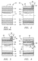
- Figure 1 illustrates a lined bearing 10, typical of the prior art, as used, for example, as an aircraft track roller bearing.
- An outer bearing ring 12 and inner bearing ring 14 are concentric about an axis 16 and are typically made of stainless steel.
- a bearing liner 18, located within an annular space between the bearing rings, may be made of a polymer material.
- Figure 2 illustrates a lined bearing 20 of the present invention, including a wear sensor.
- An outer bearing ring 22 and inner bearing ring 24 are concentric about an axis 26.
- One of the bearing rings 22 and 24 is stationary with respect to its mounting and the other bearing ring is rotatable about the axis 26.
- a bearing liner 28 is located within an annular space between the outer bearing ring 22 and inner bearing ring 24 and is fixed to the stationary bearing ring.
- a pair of electrical conductors 30 is embedded in the bearing liner 28 such that each conductor, designated A or B, is coiled in a helix or similar form with at least one loop encircling the inner bearing ring 24.
- a and B alternate along the axial length of the bearing and are electrically isolated from each other.
- the electrical conductors 30 are located within the bearing liner 28, along the stationary bearing ring, such that wear of the bearing liner will cause the rotatable bearing ring to contact and electrically connect electrical conductors A and B.
- the bearing liner 28 is made of a low-friction polymer, such as a TFE (teflon) composite, and is a poor conductor of electricity, avoiding the need to provide separate insulation of the electrical conductors 30.
- a low-friction polymer such as a TFE (teflon) composite
- they can be coated with enamel or other coating similar to that used with magnet wire.
- the outer bearing ring 22 is stationary and the inner bearing ring 24 is rotatable about the axis 26 relative to the outer bearing ring 22. At least one opening 32 within the stationary bearing ring is provided to permit electrical connection to detecting means and a remote monitor by external wires.
- Figure 3 illustrates the lined bearing 20 after excessive wear, and is enumerated as lined bearing 34 to distinguish the initial configuration.
- the outer bearing ring 22 is unchanged and the inner bearing ring 36 shows little wear but is no longer concentric about the axis 26.
- a bearing liner upper portion 38 shows little wear but a bearing liner lower portion 40 shows excessive wear.
- the excessive wear causes shorting of the electrical conductors 30 due to contact with the rotating inner bearing ring 36 that is made of metal or is coated to conduct electricity. If the electrical conductors 30 are coated to ensure electrical isolation, as described above, the coating will easily wear away when the rotating bearing ring rubs against the coating.
- Figure 4 illustrates a lined bearing 42 similar to the lined bearings 20 and 34 but having a stationary inner bearing ring 46, as found in a typical track roller bearing.
- An outer bearing ring 44 is similar to the outer bearing ring 22 of Figure 2.
- the inner bearing ring 46 is not concentric about the axis 48 due to excessive wear of the rotating outer bearing ring against a bearing liner 50 at a portion 52.
- Electrical conductors 54 are coiled around the inner bearing ring 46 in alternating A and B locations to indicate excessive wear, similar to the electrical conductors 30 of the first embodiment.
- the bearing liner is fixed to the stationary inner bearing ring 46 and is electrically connected to detector means and a remote monitor through at least one opening 56.
- Figure 5 illustrates schematically a simple means for detecting the electrical connection of the electrical conductors 30 or 54 that results with excessive wear.
- An ohmmeter 60 senses the decreased electrical resistance between A and B and can serve as a remote monitor of the lined bearing.
- a power source 62 may apply a voltage to either A or B, as illustrated schematically in Figure 6, and a voltmeter 64 may be used as a remote monitor of the lined bearing.
- Resistors 66 and 68 serve as biasing resistors and a transistor 70 serves as a switch.
- Figure 7 illustrates schematically a fuselage 72 of an airplane equipped with several lined bearings 74 along a rear control surface 76 of a wing 78. Electrical wires 80, in pairs, are joined as cable 82 connecting lined bearings 74 to a signal processing means 84.
- the signal processing means 84 may be a simple switch enabling manual connection of a detector similar to those of Figures 5 an 6 to one of the lined bearings 74 or may be more automated, such as a computerized multiplexer and signal conditioner for sequential testing of the lined bearings 74.
- Output for the signal processing means 84 may be connected by electrical wires 86 to a warning lamp or other cockpit display 88.
- the signal processing means may also, be made detachable for use by ground crews, if the built-in test feature is not desired.
- the present construction provides an effective and convenient means of monitoring lined bearings to sense excessive wear.
- Electrical conductors that serve as sensing elements are placed selectively with the bearing liner to permit only the desired amount of wear, and electrical connections are led through the stationary bearing ring without interfering with operation of the lined bearings.
- the wear sensor is particularly suited for use with airplane control surfaces using large numbers of lined bearings.
Abstract
A bearing liner (28) between inner and outer bearing rings (22, 24), one stationary and the other rotatable, is fixed to the stationary bearing ring. A pair of electrical conductors (30), coiled in at least one loop encircling the inner bearing ring (24), is embedded within the bearing liner (28). The electrical conductors are electrically isolated and located such that wear of the bearing liner causes the rotatable bearing ring to contact and electrically connect the electrical conductors. An electrical circuit detects the electrical connection to indicate wear of the bearing liner.
Description
- This invention relates generally to lined bearings and, more particularly, to a lined bearing with a sensor permitting remote monitoring of wear.
- Lined bearings are used in a wide variety of applications and, due to improvements in bearing design and bearing materials, lined bearings are now used in many applications where rolling element bearings were used previously. On many aircraft, for example, lined bearings with a liner of polymer material may be used in place of needle roller bearings to realise substantial savings in weight and complexity. However, because large numbers of such bearings are required to support the movable control surfaces on large aircraft, considerable effort and expense are required periodically to check each of the lined bearings for excessive wear.
- According to one aspect of the present invention, there is provided a lined bearing comprising an inner bearing ring having an axis, an outer bearing ring concentric with the inner bearing ring and providing an annular space therebetween, one of the inner bearing ring and the outer bearing ring being stationary and the other of the inner bearing ring and the outer bearing ring being rotatable about the axis, and a bearing liner within the annular space and fixed to the stationary bearing ring, characterised in that a pair of electrical conductors are embedded in the bearing liner, coiled in at least one loop encircling the inner bearing ring, each of the electrical conductors being electrically isolated and located such that wear of the bearing liner will cause the rotatable bearing ring to contact and electrically connect the electrical conductors.
- According to a second aspect of the present invention, there is provided a system for monitoring wear of lined bearings, the system comprising a plurality of lined bearings, each of the lined bearings having an axis, an inner bearing ring, an outer bearing ring concentric with the inner bearing ring, one of the inner bearing ring and the outer bearing ring being stationary and the other of the inner bearing ring and the outer bearing ring being rotatable about the axis, and a bearing liner between the inner bearing ring and the outer bearing ring and fixed to the stationary bearing ring; characterised by a pair of electrical conductors embedded in the bearing liner in each of said bearings, each pair of electrical conductors being coiled in at least one loop encircling the inner bearing ring and each of the electrical conductors being electrically isolated and located such that excessive wear of the bearing liner will cause said rotatable bearing ring to contact and electrically connect the electrical conductors, and signal processing means for processing electrical signals from the electrical conductors of the lined bearings to indicate wear of the bearing liner of each of the lined bearings.
- For a better understanding of the present invention and to show how the same may be carried into effect, reference will now be made, by way of example, to the accompanying drawings, in which:-
- Figure 1 is a cross-sectional view of a typical lined bearing according to the prior art;
- Figure 2 is a cross-sectional view of a lined bearing with wear sensor illustrating a first embodiment of the present invention;
- Figure 3 is a cross-sectional view of the lined bearing with wear sensor of Figure 2, following excessive wear;
- Figure 4 is a cross-sectional view of a lined bearing with wear sensor illustrating a second embodiment of the present invention, following excessive wear;
- Figure 5 is a schematic drawing of an electrical circuit for monitoring the condition of the lined bearing with wear sensor of the present invention;
- Figure 6 is a schematic drawing of an alternative electrical circuit to monitor the condition of the lined bearing with wear sensor of the present invention; and
- Figure 7 is a schematic drawing of a typical aircraft application of the lined bearing with wear sensor of the present invention.
- Figure 1 illustrates a lined
bearing 10, typical of the prior art, as used, for example, as an aircraft track roller bearing. Anouter bearing ring 12 andinner bearing ring 14 are concentric about anaxis 16 and are typically made of stainless steel. Abearing liner 18, located within an annular space between the bearing rings, may be made of a polymer material. - Figure 2 illustrates a lined
bearing 20 of the present invention, including a wear sensor. Anouter bearing ring 22 andinner bearing ring 24 are concentric about anaxis 26. One of thebearing rings axis 26. Abearing liner 28 is located within an annular space between theouter bearing ring 22 andinner bearing ring 24 and is fixed to the stationary bearing ring. - A pair of
electrical conductors 30 is embedded in thebearing liner 28 such that each conductor, designated A or B, is coiled in a helix or similar form with at least one loop encircling theinner bearing ring 24. A and B alternate along the axial length of the bearing and are electrically isolated from each other. Theelectrical conductors 30 are located within thebearing liner 28, along the stationary bearing ring, such that wear of the bearing liner will cause the rotatable bearing ring to contact and electrically connect electrical conductors A and B. - Preferably, the
bearing liner 28 is made of a low-friction polymer, such as a TFE (teflon) composite, and is a poor conductor of electricity, avoiding the need to provide separate insulation of theelectrical conductors 30. However, to ensure good electrical isolation of the conductors, they can be coated with enamel or other coating similar to that used with magnet wire. In the embodiment of Figure 2, theouter bearing ring 22 is stationary and theinner bearing ring 24 is rotatable about theaxis 26 relative to theouter bearing ring 22. At least one opening 32 within the stationary bearing ring is provided to permit electrical connection to detecting means and a remote monitor by external wires. - Figure 3 illustrates the lined
bearing 20 after excessive wear, and is enumerated as linedbearing 34 to distinguish the initial configuration. Theouter bearing ring 22 is unchanged and the inner bearingring 36 shows little wear but is no longer concentric about theaxis 26. A bearing linerupper portion 38 shows little wear but a bearing linerlower portion 40 shows excessive wear. The excessive wear causes shorting of theelectrical conductors 30 due to contact with the rotatinginner bearing ring 36 that is made of metal or is coated to conduct electricity. If theelectrical conductors 30 are coated to ensure electrical isolation, as described above, the coating will easily wear away when the rotating bearing ring rubs against the coating. - Figure 4 illustrates a lined
bearing 42 similar to the linedbearings inner bearing ring 46, as found in a typical track roller bearing. Anouter bearing ring 44 is similar to theouter bearing ring 22 of Figure 2. Theinner bearing ring 46 is not concentric about theaxis 48 due to excessive wear of the rotating outer bearing ring against abearing liner 50 at aportion 52.Electrical conductors 54 are coiled around theinner bearing ring 46 in alternating A and B locations to indicate excessive wear, similar to theelectrical conductors 30 of the first embodiment. The bearing liner is fixed to the stationaryinner bearing ring 46 and is electrically connected to detector means and a remote monitor through at least one opening 56. - Figure 5 illustrates schematically a simple means for detecting the electrical connection of the
electrical conductors ohmmeter 60 senses the decreased electrical resistance between A and B and can serve as a remote monitor of the lined bearing. Alternatively, apower source 62 may apply a voltage to either A or B, as illustrated schematically in Figure 6, and avoltmeter 64 may be used as a remote monitor of the lined bearing.Resistors transistor 70 serves as a switch. When theelectrical conductors - Figure 7 illustrates schematically a
fuselage 72 of an airplane equipped with several linedbearings 74 along arear control surface 76 of awing 78.Electrical wires 80, in pairs, are joined ascable 82 connecting linedbearings 74 to a signal processing means 84. The signal processing means 84 may be a simple switch enabling manual connection of a detector similar to those of Figures 5 an 6 to one of the linedbearings 74 or may be more automated, such as a computerized multiplexer and signal conditioner for sequential testing of the linedbearings 74. Output for the signal processing means 84 may be connected byelectrical wires 86 to a warning lamp orother cockpit display 88. The signal processing means may also, be made detachable for use by ground crews, if the built-in test feature is not desired. - From the above description, it will be apparent that the present construction provides an effective and convenient means of monitoring lined bearings to sense excessive wear. Electrical conductors that serve as sensing elements are placed selectively with the bearing liner to permit only the desired amount of wear, and electrical connections are led through the stationary bearing ring without interfering with operation of the lined bearings. The wear sensor is particularly suited for use with airplane control surfaces using large numbers of lined bearings.
Claims (15)
- A lined bearing comprising an inner bearing ring (24) having an axis (26), an outer bearing ring (22) concentric with the inner bearing ring and providing an annular space therebetween, one of the inner bearing ring and the outer bearing ring being stationary and the other of the inner bearing ring and the outer bearing ring being rotatable about the axis (26), and a bearing liner (28) within the annular space and fixed to the stationary bearing ring, characterised in that a pair of electrical conductors (30) are embedded in the bearing liner (28), coiled in at least one loop encircling the inner bearing ring (24), each of the electrical conductors being electrically isolated and located such that wear of the bearing liner (28) will cause the rotatable bearing ring to contact and electrically connect the electrical conductors (30).
- A lined bearing according to claim 1, wherein the bearing liner (28) has two axial ends and said at least one loop encircling the inner bearing ring (24) extends from one axial end of the bearing liner to the other axial end of the bearing liner.
- A lined bearing according to claim 1 or 2, wherein the inner bearing ring (46) is the stationary bearing ring.
- A lined bearing according to claim 1 or 2, wherein the outer bearing ring (22) is the stationary bearing ring.
- A lined bearing according to any one of the preceding claims, wherein the coiled electrical conductors form a helix.
- A lined bearing according to any one of the preceding claims, wherein the pair of electrical conductors (30) are parallel and adjacent such that they have the same pitch and diameter and alternate in the axial direction.
- A lined bearing according to any one of the preceding claims, further comprising detecting means (60) for detecting the electrical connection of the electrical conductors (30) to indicate wear of the bearing liner (28).
- A lined bearing according to claim 7, wherein the detecting means includes an ohmmeter to detect a shorting of the electrical conductors.
- A lined bearing according to claim 7, wherein the detecting means includes a voltmeter (64) to indicate a reduction in current passed through the electrical conductors.
- A lined bearing according to claim 7, 8 or 9, wherein the detecting means includes wires passing through said stationary bearing ring.
- A lined bearing according to claim 7, 8, 9 or 10, further comprising means for connecting the detecting means to a remote visual display (88).
- A system for monitoring wear of lined bearings, the system comprising a plurality of lined bearings (20), each of the lined bearings having an axis (26), an inner bearing ring (24), an outer bearing ring (22) concentric with the inner bearing ring, one of the inner bearing ring and the outer bearing ring being stationary and the other of the inner bearing ring and the outer bearing ring being rotatable about the axis (26), and a bearing liner (28) between the inner bearing ring and the outer bearing ring and fixed to the stationary bearing ring; characterised by a pair of electrical conductors (30) embedded in the bearing liner (28) in each of said bearings, each pair of electrical conductors being coiled in at least one loop encircling the inner bearing ring (24) and each of the electrical conductors being electrically isolated and located such that excessive wear of the bearing liner will cause said rotatable bearing ring to contact and electrically connect the electrical conductors, and signal processing means (84) for processing electrical signals from the electrical conductors of the lined bearings to indicate wear of the bearing liner of each of the lined bearings.
- A system according to claim 12, further comprising a remote display (86), connected to the signal processing means, to provide a warning of excessive wear of the bearing liners of the lined bearings.
- A system according to claim 12 or 13, wherein the signal processing means includes a multiplexer and signal coordinator.
- A system according to claim 12, 13 or 14, wherein the signal processing means is detachable from the electrical conductors.
Applications Claiming Priority (2)
| Application Number | Priority Date | Filing Date | Title |
|---|---|---|---|
| US50930695A | 1995-07-31 | 1995-07-31 | |
| US509306 | 1995-07-31 |
Publications (1)
| Publication Number | Publication Date |
|---|---|
| EP0760434A1 true EP0760434A1 (en) | 1997-03-05 |
Family
ID=24026104
Family Applications (1)
| Application Number | Title | Priority Date | Filing Date |
|---|---|---|---|
| EP19960305668 Withdrawn EP0760434A1 (en) | 1995-07-31 | 1996-07-31 | Lined bearing with wear sensor |
Country Status (3)
| Country | Link |
|---|---|
| US (1) | US5701119A (en) |
| EP (1) | EP0760434A1 (en) |
| CA (1) | CA2182445A1 (en) |
Cited By (4)
| Publication number | Priority date | Publication date | Assignee | Title |
|---|---|---|---|---|
| DE19915348A1 (en) * | 1999-04-06 | 2000-10-12 | Schaeffler Waelzlager Ohg | Sliding bearing with an arrangement for monitoring its wear comprises a contactor which is an integral consistent of the glide layer, and serves to issue a warning signal when limit wear of this layer is exceeded |
| FR2833321A1 (en) * | 2001-12-11 | 2003-06-13 | Irisbus France | Ball and socket joint for vehicle, comprises pivot, box and intervening non conducting friction element, also contains electrical circuit with fuse and alarm which is activated when friction element is worn |
| DE10324924A1 (en) * | 2003-06-03 | 2004-12-23 | Ab Skf | Sleeve bearing with spherical or cylindrical baring surfaces has sensor attached to first bearing ring to detect measurement parameter dependent on distance of sensor from second bearing surface |
| EP2689154A4 (en) * | 2011-03-22 | 2015-05-13 | Saint Gobain Performance Plast | Bushing with transfigurable electrical conduction state |
Families Citing this family (24)
| Publication number | Priority date | Publication date | Assignee | Title |
|---|---|---|---|---|
| US6206573B1 (en) * | 1998-05-21 | 2001-03-27 | Lsi Logic Corporation | High reliability bearing structure |
| US5998894A (en) * | 1998-08-04 | 1999-12-07 | Pacific Scientific | Modular bearing failure sensor for an electrical generator |
| US6595045B1 (en) | 2000-10-16 | 2003-07-22 | Veridian Engineering, Inc. | Vehicular sensors |
| US6498470B2 (en) | 2001-03-02 | 2002-12-24 | Honeywell International, Inc. | Insulative contact sensor |
| US7034711B2 (en) * | 2001-08-07 | 2006-04-25 | Nsk Ltd. | Wireless sensor, rolling bearing with sensor, management apparatus and monitoring system |
| DE10140683A1 (en) * | 2001-08-24 | 2003-03-06 | Zf Lemfoerder Metallwaren Ag | ball joint |
| DE10159071A1 (en) * | 2001-12-01 | 2003-06-12 | Ina Schaeffler Kg | Wear indicating unit for a tension device for an automotive engine, used e.g. for a belt or chain for a water pump, injection pump or automotive air-conditioning unit |
| US7270890B2 (en) * | 2002-09-23 | 2007-09-18 | Siemens Power Generation, Inc. | Wear monitoring system with embedded conductors |
| US7452155B2 (en) * | 2003-02-27 | 2008-11-18 | ZF Lemförder Metallwaren AG | Ball and socket joint |
| US8264347B2 (en) * | 2008-06-24 | 2012-09-11 | Trelleborg Sealing Solutions Us, Inc. | Seal system in situ lifetime measurement |
| DE102012106295A1 (en) * | 2012-07-12 | 2014-10-30 | Institut Für Verbundwerkstoffe Gmbh | Slide bearing and method for determining the wear of a plain bearing |
| DE102014204824A1 (en) * | 2014-03-14 | 2015-09-17 | Invent Umwelt-Und Verfahrenstechnik Ag | Stirring device for wastewater |
| DE102014110383A1 (en) | 2014-04-01 | 2015-10-01 | Becker Marine Systems Gmbh & Co. Kg | Bearing for supporting a shaft, in particular a rudder stock, electronic bearing clearance measuring device, rudder comprising a bearing for supporting a shaft and method for measuring a wear of a bearing for supporting a shaft |
| GB2534191A (en) * | 2015-01-16 | 2016-07-20 | Mahle Int Gmbh | Sliding bearing |
| JP6491060B2 (en) | 2015-08-21 | 2019-03-27 | ミネベアミツミ株式会社 | Sliding parts, wear detection system and yaw system provided with the same, and wind turbine generator including the yaw system |
| DE202016102133U1 (en) * | 2016-04-21 | 2017-05-23 | Igus Gmbh | Slide bearing, plastic sliding element, system and use for wear detection |
| CN114948106A (en) | 2017-05-03 | 2022-08-30 | 美敦力瓦斯科尔勒公司 | Tissue removal catheter with guidewire isolation bushing |
| US11690645B2 (en) | 2017-05-03 | 2023-07-04 | Medtronic Vascular, Inc. | Tissue-removing catheter |
| GB2565555B (en) * | 2017-08-15 | 2020-07-08 | Mahle Int Gmbh | Sliding component and method |
| CN112997016B (en) * | 2018-10-08 | 2023-06-02 | 易格斯有限公司 | Plastic sliding element with sensor function, in particular with wear detection |
| US11819236B2 (en) | 2019-05-17 | 2023-11-21 | Medtronic Vascular, Inc. | Tissue-removing catheter |
| DE102019008762A1 (en) * | 2019-12-14 | 2021-06-17 | Hochschule Mittweida (Fh) | Device for monitoring a plain bearing with a first part and a second part which can be moved relative to one another |
| EP3992487A1 (en) * | 2020-10-30 | 2022-05-04 | Meritor Heavy Vehicle Braking Systems (UK) Limited | A guide assembly for a disc brake |
| EP4047233A1 (en) * | 2021-02-17 | 2022-08-24 | Flender GmbH | Torsionally elastic coupling with wear sensor |
Citations (5)
| Publication number | Priority date | Publication date | Assignee | Title |
|---|---|---|---|---|
| DE2115506A1 (en) * | 1971-03-31 | 1972-10-05 | Kloeckner Werke Ag | Device for monitoring the wear and tear of bearings |
| JPS5618119A (en) * | 1979-07-20 | 1981-02-20 | Hitachi Ltd | Life detection of oilless type solid lubricating material |
| US4320431A (en) * | 1980-02-26 | 1982-03-16 | Westinghouse Electric Corp. | Fluid circulating pump |
| JPS6154402A (en) * | 1984-08-27 | 1986-03-18 | Inoue Japax Res Inc | Method for detecting abrasion of synthetic resin machine component |
| GB2192949A (en) * | 1986-07-25 | 1988-01-27 | Wickers Shipbuilding & Enginee | Indicating wear in bearings |
Family Cites Families (6)
| Publication number | Priority date | Publication date | Assignee | Title |
|---|---|---|---|---|
| US3108264A (en) * | 1957-07-08 | 1963-10-22 | Heinoo Lauri | Bearing wear sensor |
| US3102759A (en) * | 1960-05-19 | 1963-09-03 | John T Stewart | Journal bearing wear detector |
| NO134348C (en) * | 1971-02-22 | 1976-09-22 | Asea Ab | |
| US3897116A (en) * | 1971-10-07 | 1975-07-29 | Crane Co | Bearing wear detector |
| SU727886A1 (en) * | 1978-07-26 | 1980-04-15 | Воинская Часть 27177-Е | Apparatus for determining sliding-contact bearing wear |
| US4584865A (en) * | 1984-07-30 | 1986-04-29 | Lawrence Pump And Engine Company | Device and method for testing for motor bearing wear |
-
1996
- 1996-07-31 EP EP19960305668 patent/EP0760434A1/en not_active Withdrawn
- 1996-07-31 CA CA 2182445 patent/CA2182445A1/en not_active Abandoned
-
1997
- 1997-01-13 US US08/782,375 patent/US5701119A/en not_active Expired - Lifetime
Patent Citations (5)
| Publication number | Priority date | Publication date | Assignee | Title |
|---|---|---|---|---|
| DE2115506A1 (en) * | 1971-03-31 | 1972-10-05 | Kloeckner Werke Ag | Device for monitoring the wear and tear of bearings |
| JPS5618119A (en) * | 1979-07-20 | 1981-02-20 | Hitachi Ltd | Life detection of oilless type solid lubricating material |
| US4320431A (en) * | 1980-02-26 | 1982-03-16 | Westinghouse Electric Corp. | Fluid circulating pump |
| JPS6154402A (en) * | 1984-08-27 | 1986-03-18 | Inoue Japax Res Inc | Method for detecting abrasion of synthetic resin machine component |
| GB2192949A (en) * | 1986-07-25 | 1988-01-27 | Wickers Shipbuilding & Enginee | Indicating wear in bearings |
Cited By (6)
| Publication number | Priority date | Publication date | Assignee | Title |
|---|---|---|---|---|
| DE19915348A1 (en) * | 1999-04-06 | 2000-10-12 | Schaeffler Waelzlager Ohg | Sliding bearing with an arrangement for monitoring its wear comprises a contactor which is an integral consistent of the glide layer, and serves to issue a warning signal when limit wear of this layer is exceeded |
| DE19915348B4 (en) * | 1999-04-06 | 2019-06-27 | Schaeffler Technologies AG & Co. KG | bearings |
| FR2833321A1 (en) * | 2001-12-11 | 2003-06-13 | Irisbus France | Ball and socket joint for vehicle, comprises pivot, box and intervening non conducting friction element, also contains electrical circuit with fuse and alarm which is activated when friction element is worn |
| DE10324924A1 (en) * | 2003-06-03 | 2004-12-23 | Ab Skf | Sleeve bearing with spherical or cylindrical baring surfaces has sensor attached to first bearing ring to detect measurement parameter dependent on distance of sensor from second bearing surface |
| DE10324924B4 (en) | 2003-06-03 | 2021-08-26 | Ab Skf | Method for determining a load absorbed by a plain bearing with spherical or cylindrical bearing surfaces |
| EP2689154A4 (en) * | 2011-03-22 | 2015-05-13 | Saint Gobain Performance Plast | Bushing with transfigurable electrical conduction state |
Also Published As
| Publication number | Publication date |
|---|---|
| CA2182445A1 (en) | 1997-02-01 |
| US5701119A (en) | 1997-12-23 |
Similar Documents
| Publication | Publication Date | Title |
|---|---|---|
| US5701119A (en) | Lined bearing with wear sensor | |
| US4387336A (en) | Method and apparatus for cable conductor shield fault detection | |
| US8319628B2 (en) | Three-phase faulted circuit indicator | |
| US6653943B2 (en) | Suspension rope wear detector | |
| CN104426039B (en) | Slip ring unit and the method for detecting the state of slip ring unit | |
| US4553432A (en) | Temperature-humidity surveillance equipment | |
| US4988949A (en) | Apparatus for detecting excessive chafing of a cable arrangement against an electrically grounded structure | |
| US4493155A (en) | Apparatus for remotely indicating angular position | |
| US3320524A (en) | Apparatus including electrode means for determining electrical condition of aerial booms for energized line working | |
| US20180017611A1 (en) | Method and apparatus for an electrical fault detecting system for a circuit | |
| CA2329405C (en) | Contact-connecting safety-monitored synthetic fiber ropes | |
| EP3168361B1 (en) | Aircraft rescue hoist rope designed for continuous inspection | |
| GB2042182A (en) | Magnetic contamination detector | |
| JP2009143678A (en) | Rope inspecting device of elevator | |
| US5020741A (en) | Aircraft propeller with improved electrically de-icer leads | |
| EP0356017A2 (en) | Liquid leakage detection apparatus | |
| CN108646131A (en) | A kind of broken strand of steel-cored aluminium strand wire detection device and method | |
| US3710241A (en) | Apparatus for detecting faults in extruded insulating or dielectric material | |
| CN107340421A (en) | A kind of current sensor | |
| JP4257839B2 (en) | Ground fault detection device for power cable shielding conductor | |
| US3763426A (en) | Method and apparatus for testing twisted pair wire to locate electrical insulation faults or measure twist or wire runout or sense breaks in the conductors | |
| US4734642A (en) | Device for use in eddy current testing for transmission of signals between a signal processing device and a signal source | |
| US6498470B2 (en) | Insulative contact sensor | |
| CN209707433U (en) | The ultra-thin part capacitance chromatography imaging device of irregular geometry shape | |
| CN208384038U (en) | A kind of broken strand of steel-cored aluminium strand wire detection device |
Legal Events
| Date | Code | Title | Description |
|---|---|---|---|
| PUAI | Public reference made under article 153(3) epc to a published international application that has entered the european phase |
Free format text: ORIGINAL CODE: 0009012 |
|
| AK | Designated contracting states |
Kind code of ref document: A1 Designated state(s): DE FR GB SE |
|
| 17P | Request for examination filed |
Effective date: 19970822 |
|
| 17Q | First examination report despatched |
Effective date: 19980827 |
|
| STAA | Information on the status of an ep patent application or granted ep patent |
Free format text: STATUS: THE APPLICATION IS DEEMED TO BE WITHDRAWN |
|
| 18D | Application deemed to be withdrawn |
Effective date: 19990108 |