EP0760427B1 - High capacity, large sphere passing, slurry pump - Google Patents
High capacity, large sphere passing, slurry pump Download PDFInfo
- Publication number
- EP0760427B1 EP0760427B1 EP96306246A EP96306246A EP0760427B1 EP 0760427 B1 EP0760427 B1 EP 0760427B1 EP 96306246 A EP96306246 A EP 96306246A EP 96306246 A EP96306246 A EP 96306246A EP 0760427 B1 EP0760427 B1 EP 0760427B1
- Authority
- EP
- European Patent Office
- Prior art keywords
- diameter
- pump
- impeller
- approximately
- centrifugal pump
- Prior art date
- Legal status (The legal status is an assumption and is not a legal conclusion. Google has not performed a legal analysis and makes no representation as to the accuracy of the status listed.)
- Expired - Lifetime
Links
- 239000002002 slurry Substances 0.000 title claims description 25
- 239000007787 solid Substances 0.000 claims description 5
- 239000012530 fluid Substances 0.000 claims description 3
- 238000004891 communication Methods 0.000 claims description 2
- XLYOFNOQVPJJNP-UHFFFAOYSA-N water Substances O XLYOFNOQVPJJNP-UHFFFAOYSA-N 0.000 description 12
- 239000007788 liquid Substances 0.000 description 10
- 238000013461 design Methods 0.000 description 4
- 238000010586 diagram Methods 0.000 description 4
- 239000002245 particle Substances 0.000 description 4
- 229910001037 White iron Inorganic materials 0.000 description 3
- 239000000463 material Substances 0.000 description 3
- 238000005299 abrasion Methods 0.000 description 2
- 238000010276 construction Methods 0.000 description 2
- 230000005484 gravity Effects 0.000 description 2
- 238000005086 pumping Methods 0.000 description 2
- 239000004576 sand Substances 0.000 description 2
- 238000012360 testing method Methods 0.000 description 2
- 230000002411 adverse Effects 0.000 description 1
- 239000010432 diamond Substances 0.000 description 1
- 238000007599 discharging Methods 0.000 description 1
- 230000000694 effects Effects 0.000 description 1
- 230000003628 erosive effect Effects 0.000 description 1
- -1 gravel Substances 0.000 description 1
- 238000004519 manufacturing process Methods 0.000 description 1
- 239000011317 mixed pitch Substances 0.000 description 1
- 239000000203 mixture Substances 0.000 description 1
- 238000012986 modification Methods 0.000 description 1
- 230000004048 modification Effects 0.000 description 1
- 238000012856 packing Methods 0.000 description 1
- 230000002093 peripheral effect Effects 0.000 description 1
- 239000011435 rock Substances 0.000 description 1
- 230000003746 surface roughness Effects 0.000 description 1
Images


Classifications
-
- F—MECHANICAL ENGINEERING; LIGHTING; HEATING; WEAPONS; BLASTING
- F04—POSITIVE - DISPLACEMENT MACHINES FOR LIQUIDS; PUMPS FOR LIQUIDS OR ELASTIC FLUIDS
- F04D—NON-POSITIVE-DISPLACEMENT PUMPS
- F04D29/00—Details, component parts, or accessories
- F04D29/18—Rotors
- F04D29/22—Rotors specially for centrifugal pumps
- F04D29/2238—Special flow patterns
- F04D29/225—Channel wheels, e.g. one blade or one flow channel
-
- F—MECHANICAL ENGINEERING; LIGHTING; HEATING; WEAPONS; BLASTING
- F04—POSITIVE - DISPLACEMENT MACHINES FOR LIQUIDS; PUMPS FOR LIQUIDS OR ELASTIC FLUIDS
- F04D—NON-POSITIVE-DISPLACEMENT PUMPS
- F04D29/00—Details, component parts, or accessories
- F04D29/18—Rotors
- F04D29/22—Rotors specially for centrifugal pumps
- F04D29/2205—Conventional flow pattern
- F04D29/2216—Shape, geometry
-
- F—MECHANICAL ENGINEERING; LIGHTING; HEATING; WEAPONS; BLASTING
- F04—POSITIVE - DISPLACEMENT MACHINES FOR LIQUIDS; PUMPS FOR LIQUIDS OR ELASTIC FLUIDS
- F04D—NON-POSITIVE-DISPLACEMENT PUMPS
- F04D7/00—Pumps adapted for handling specific fluids, e.g. by selection of specific materials for pumps or pump parts
- F04D7/02—Pumps adapted for handling specific fluids, e.g. by selection of specific materials for pumps or pump parts of centrifugal type
- F04D7/04—Pumps adapted for handling specific fluids, e.g. by selection of specific materials for pumps or pump parts of centrifugal type the fluids being viscous or non-homogenous
Definitions
- This invention relates to a centrifugal pump and is more particularly concerned with a high capacity, large sphere-passing slurry pump.
- centrifugal pumps have been used extensively for pumping slurries. Dredging operations often utilize two or more tandemly arranged centrifugal pumps to pump slurries.
- the slurries may consist of any fluid and particles.
- the particles may be as small as a few microns to as large as 508 mm (20 inches) or more and the density of the slurry mixture may be higher than 1.8 times the density of water.
- centrifugal water pumps may pump slurries having a low particulate concentration, but once such particles become large or if the particle concentration becomes large, the erosion and wear of the various parts become so severe that special designs and constructions for the pump are necessary to provide an acceptable pump service life. Where wear is a severe problem, the centrifugal pumps are usually made of white iron and have quite thick impeller vanes which will withstand the abrasion.
- centrifugal pump When dredging operations require a centrifugal pump to be used as a dredge pump for removing materials such as sand, gravel and other objects from an ocean floor, it is not unusual for such a pump to be required to remove spheres or sphere-like objects, as large as 508 millimeters (20 inches) from time to time. Modifications to the centrifugal pump's hydraulic passage, inlet cross-sectional area, sphere clearance which are necessary to provide acceptable performance in passing those large objects, generally have an adverse affect on the hydraulic and mechanical efficiency of such centrifugal pumps.
- Ladder pumps urge the water and aggregate, such as sand, gravel, rocks and relatively large spheres or sphere-like objects into the suction nozzle of the onboard centrifugal pump, by generating a vacuum at the intake of the ladder pump and then discharging this slurry through the ladder pump discharge nozzle and into a pipe leading upwardly to the onboard pump.
- the prime mover for the ladder pump may be adjacent to the pump or onboard the vessel where appropriate shafts and gears transmit the power to the submerged ladder pump.
- the onboard dredge pump is usually mounted near the prime mover or where it can be readily and easily accessed by an operator, who may also steer the dredging vessel.
- NPSH net positive suction head
- the impeller of a typical, rather small diameter modern ladder pump has an effective diameter usually only 125% of the suction diameter intake of the pump, which limits the size of sphere-like objects which will pass through the typical pump.
- the sphere-like objects are required to pass between the leading edge of the leading face or surface of one vane and the trailing face of the next adjacent vane.
- Such pumps are also required to be made of abrasive resistant material, such as white iron.
- the vanes, themselves, are quite thick to withstand very substantial abrasion during operation.
- a pump having a tubular shell portion which has at least two blades attached thereto, such that the entire housing spins with the impeller blades. By attaching the blades to the housing, gaps between the housing and the blades are eliminated.
- US-A-3130679 discloses a centrifugal pump comprising a shell in the form of a semi-volute collector having a substantially circular front wall and a spaced substantially circular back wall, a generally continuous outer side wall and a spaced substantially circular back wall, a generally continuous outer side wall extending between said front wall and said back wall, a discharge nozzle disposed tangentially with respect to said side wall, a discharge opening at a terminal end of said discharge nozzle and a circular suction inlet defined in said front wall; an impeller rotatably supported within said shell, said impeller including a circular back shroud; a plurality of vanes, said vanes being equally spaced from each other and defining impeller channels therebetween; and protruding generally forwardly from said back shroud and opening in a forward direction; a drive shaft rotatably supported on said shell, said shaft being operably engaged with said back shroud and being connected to a prime mover for rotating said impeller.
- a spaced annular shroud to which the distal ends of the vanes are fastened and which defines a circular opening which is in fluid communication with said suction inlet, said circular opening having a diameter approximately equal to a diameter of said suction inlet; and the size of each of said impeller channels equals approximately 34% to approximately 40% of said diameter of said circular opening defined by said annular shroud.
- the present invention seeks to overcome the problems of the prior art by providing a centrifugal pump which, while being capable of passing relatively large spheres or sphere-like objects, is compact, rugged, efficient and particularly suited for pumping the large spheres and for use as a ladder pump.
- the present invention preferably includes a low head (low power) centrifugal ladder pump which has wear-resistant, semi-volute shell which houses an impeller.
- the impeller may include a restricted number of vanes of negative (no) overlap, which are capable of passing the relatively large spheres or sphere-like objects through the impeller-channels and which still are capable of achieving a respectable efficiency and a substantial net positive suction head (NPSH) performance.
- the impeller of the present invention may include three circumferentially, equally spaced, mixed flow vanes, rear ends of which originate from a rear shroud and forward ends of which terminate on a rear surface of an open annular shroud.
- the shroud of the impeller has a larger outside diameter than an outside diameter of the back shroud and each vane tapers toward the shroud.
- the vanes diverge forwardly from each other to a centre portion of the back shroud.
- the inner or trailing faces of the vanes are concave, the outer surfaces or leading faces of the vanes are convex, and the trailing surfaces are concave.
- Each vane has a specification as to curvature of these opposed surfaces along their lengths.
- the impeller of the present invention is of special design and operates with a particular type of collector.
- the impeller vanes are of mixed flow design with a near radial outlet.
- centrifugal-type slurry pump which is designed to pass large spheres or sphere-like objects in the slurry through the pump without an appreciable loss of efficiency.
- Other preferred objects are set out below.
- Another object of the present invention is to provide a centrifugal-type slurry pump which is particularly suited as a ladder pump or dredge pump.
- Still another object of the present invention is to provide a centrifugal-type slurry pump which is particularly suitable as a ladder pump used in tandem with an onboard or inboard pump for dredging operations.
- Yet another object of the present invention is to provide a centrifugal pump which is relatively inexpensive to manufacture, durable in structure and efficient in operation.
- Another object of the present invention is to provide a centrifugal-type slurry pump which is capable of passing relatively large spheres or sphere-like objects while also being compact, rugged and efficient.
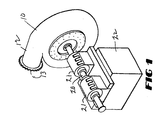
- numeral 10 denotes generally the semi-volute shell or shell collector of a centrifugal pump of the present invention.
- Shell 10 includes a discharge nozzle 12 which protrudes outwardly therefrom in a tangential direction. Discharge nozzle 12 terminates at discharge opening 13.
- the shell 10 has a hollow central interior 14 which receives the impeller, denoted generally by the numeral 15.
- Impeller 15 includes a disc-shaped back shroud 16 with a bulbous forwardly protruding central hub 17 of smaller diameter than the diameter of the back shroud 16.
- the central portion of the rear side of the back shroud 16 is internally threaded and receives the threaded end of a drive shaft 20, seen in Fig. 1.
- This drive shaft 20 protrudes away from the back shroud 16 and bearings within a pair of spaced, aligned pillar blocks 21 mounted on a common support block 22 journal shaft 20.
- a motor (not shown) rotates the shaft 20 and the impeller 15 within shell 10.
- the usual packing (not shown) for surrounding shaft 20 in the central portion of the back side of the shell 10, prevents leakage as the pump pumps the slurry.
- an open annular shroud 30 Forwardly of the back shroud 16 is an open annular shroud 30 which has a larger outside diameter than the diameter of the back shroud 16.
- This shroud 30 includes a circular central opening or intake 31.
- the shroud 30 is concentric with the back shroud 16 about the main axis ⁇ of the pump 10 and shaft 20 as is illustrated in Fig. 6.
- the periphery of the shroud 30 is machined to form a circular front surface 32 which is concentric with the remainder of the impeller 15.
- the rear shroud 16 includes a similar rear bearing surface 18 which rides against the appropriate wearing ring (not shown) within the interior of the shell 10.
- the impeller 15 is cast as an integral unit out of white iron or some other wear-resistant material.
- the vanes 40 protrude essentially forwardly from a back shroud 16, the proximal ends 40a of each vane preferably occupying an arc or sweep of about 105° along the front surface of back shroud 16 and the distal end 40b of each vane occupying an arc or sweep of 80° along the back surface of the annular shroud 30.
- the maximum impeller passage of channels 41 between the vanes 40 is about 14.25 inches (362mm) or approximately 37% of the suction inlet diameter (2 Re ) of eye 31.
- Each vane 40 is identical to the other, the vanes 40 being spaced evenly throughout the circumference of the impeller 15.
- Each vane 40 has a thickness at the inlet end of the impeller of about 4% of the suction diameter (2 Re ) .
- Each vane 40 has a body which occupies about 7% of the suction diameter (2 Re ) and each vane 40, at its tip, or proximal end 40a occupies about 4% of the suction diameter (2 Re ).
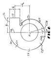
- the shell or casing 10 has a radial geometry in the plane of the impeller 15 as shown in Fig. 6.
- the width of the collector shell 10, in cross-section, may vary somewhat, but is normally about 60% of the suction diameter (2 Re ).
- the vanes 40, the front 30 and the back shroud 16 define the three circumferential spaced impeller channels 41 through which draw slurry from the impeller eye 31.
- Impeller 15 urges the slurry by centrifugal force and the orbital movement of the impeller vanes 40 outwardly into the single arcuate semi-rotate collector 10.
- the inner peripheral surface of collector 10 is defined by a progressively increasing cross-section and leads to the discharge nozzle 12, and to the opening 13.
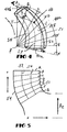
- the impeller 15 is of a special, thick, vane-type, mixed flow design, in which the channels 41 have a near radial outlet defined by the negative overlap (none) of the vanes 40, thereby providing a large sphere-like object passing capacity between the leading edge L of one vane 40 and an intermediate portion of the concaved inner surface, as specified in the relative geometry depicted in Figs. 4 and 5.
- the vane 40 includes a proximal end 40a, a distal end 40b, an inner face or surface 40c and an outer or leading face or surface 40d.
- Meridian lines A, B, C, D, E, F, G and H are spaced about 15° apart across the vane 40 at radial locations.
- the solid line labeled "L”, shown in Fig. 3, is the leading edge of vane 40 and the solid line is labeled "T" is the trailing edge.
- Tables I and II provide the parameters for the vane 40. Table I recites angles with respect to axis ⁇ in Fig. 4.
- the stream lines S1, S2, S3 and S4, indicated by broken lines in Fig. 4, are all leading face 40d stream lines along leading face 40d of vane 40.
- edge "L” and edge “T” can be ascertained with respect to the streams indicated as leading face streamline S1, S2, S3 and S4.
- the "X" and "Y” coordinates of the sections along the radial stream lines S1, S2, S3 and S4 and meridian lines A, B, C, D, E, F, G and H, the leading edge L and trailing edge T can be ascertained.
- each vane 40 at its proximal end 40a along back shroud 16 is 105° from the trailing edge T to leading edge L and the arc or sweep each vane 40 at its distal end 40b along shroud 30 is 80°, including a lag on the trailing edge of 15°.
- the maximum passage of channel 41 between the vanes 40 is close to 14.25 inches (362mm) or 37% of the suction inlet diameter (2 Re ) .
- the geometry of the impeller meridional section front and back of the impeller 15 is defined also in Table II above.
- the vanes 40 each have a thickness at their distal ends 40b adjacent the eye 31 of about 4%; along the body of vane 40 about 7%; and at the tips or proximal ends 40a of about 4%, respectively, of the suction diameter.
- the shell 10 has radial geometry in the plane of axis ⁇ (the impeller diameter) illustrated in Figs. 5 and 6.
- the width of the collector 10 in the cross-section may vary from about 55% to about 65%, but is normally 60% of the suction diameter.
- Figure 6 illustrates sections of collector 10 which are disposed every 45° around axis ⁇ , except for sections C3-C3B and C-4-C4B.
- the symbol ⁇ designates a 15° increment, and the circumferential distance between C4B and C5 is 22.5°.
- Table III below lists the coordinates of points C1 through C8 as illustrated in Fig. 6.
- the pump is capable of passing a sphere as large as 14.25 inches or 362mm, has long wearing life vanes 40 of 2.75 inches thickness or 70mm, lying within the semi-volute collector 10 that will give good wear over a wide range of ladder pump operating conditions and achieve a head quantity, efficiency and suction performance as shown in the tables of Fig. 7 and Fig. 8.
- the volume of liquid pumped is referred to as capacity and is generally measured in gallons per minute (gpm) or liters per second.
- the height to which liquid can be raised by a centrifugal pump is called total dynamic head and is measured in feet or meters. This does not depend on the nature of the liquid (its specific gravity) so long as the liquid viscosity is not higher than that of water.
- H d is the discharge head as measured at the discharge nozzle and referred to the pump shaft centerline, and is expressed in feet or meters
- H s is the suction head expressed in feet or meters as measured at the suction nozzle and referred to the same datum. If the suction head is negative, the term H s in that equation above becomes positive. The last two terms of equation above represent the difference in the kinetic energy or velocity heads at the discharge and suction nozzles.
- the degree of hydraulic and mechanical perfection of a pump is judged by its efficiency. This is defined as a ratio of pump energy output to the energy input applied to the pump shaft. The latter is the same as the driver's output and in US units is termed brake horsepower (BHP), as it generally determined by a standard brake test.
- Efficiency e pump output bhp Q y h 550 x bhp
- Q capacity in cubic feet per second
- (gpm x H)/3960 is the pump output expressed in horsepower and is referred to as water horsepower (whp). If a liquid other than cold water is used, the water horsepower should be multiplied by the specific gravity of the liquid to obtain the pump output or liquid horsepower.
- Fig. 7 graphically illustrates the characteristics of the pump 10 described above.
- the diamonds show the head, in feet, the squares indicate the efficiency as a percent of 100% and the triangles indicate the horsepower consumption of the pump.
- the inventive pump achieves a maximum head of about 50 feet with a flow of 20,000 gallons per minute and then drops to a head of about 32 feet as the pump delivers about 68,000 gallons per minute.
- Fig. 7 shows that at about 10,000 gallons per minute, the efficiency of the pump is above 30%, which is quite low; however, as the applied horsepower increases, the efficiency of the pump increases to about 85% at flows about 52,000 gallons per minute.
- Fig. 8 illustrates pump efficiency with respect to the power requirements in kilowatts, the flow in liters per second, the head generated in meters, and the efficiency as a percentage.
- the head remains essentially constant, while the efficiency of the pump increases as the flow increases up to about 3,400 liters per second, where the efficiency levels off.
- the power requirements appear to gradually increase with an increase in flow.
- the efficiency of the pump appears to level out at over 80% when delivering a large amount of slurry.
- the pump of the present invention has a very acceptable efficiency and yet will pass quite large spheres for the particular size pump.
- the pump 10 with a suction inlet diameter of 19 inches (482.6mm), vanes of 2.75 inches (70 mm) thickness and a semi-volute shell collector 10, providing the performance shown in the Fig. 8 and passes a sphere of 14.25 inches (362mm) in size.
- Pumps with different size suction inlets may have similar performance characteristics to the pump of the preferred embodiment if the dimensions of all wetted surfaces bear the same scaled proportions as the above described pump.
- a pump scaled in accordance with the present invention should have the same scaled performance, if scaled according to the generally acknowledged rules of scaling, laid out in the Hydraulic Institute Standard, except for the normal surface roughness effect, described in the Hydraulic Institute Standard.
- Centrifugal pumps constructed in accordance with the present invention should pass a solid of 37% ⁇ 3% of the suction diameter (2 Re ) .
- Q q S 3 N n ;
- H h S 2 ( N ) 2 ( n ) 2 where:
- a pump scaled exactly in every respect with the present invention with the suction diameter (2 Re ) of the impeller 15 being increased by up to 15% over the preferred embodiment and with a width of the shell collector 10 being increased by up to 25%, should then have a scaled performance, predictable in accordance with the Hydraulic Institute formulae set out above for both three dimensional true scale change and change of impeller diameter. More specifically, Hydraulic Institute scales should predict the flow characteristics and parameter performance points for head and efficiency.
- a pump scaled exactly in every respect with the present invention except that the inside diameter of the impeller 15 increased by up to 15%, and the inside widths of the shell collector 10 and the impeller 15 increased by up to 25%, would also perform according to the Hydraulic Institute scales for both three-dimensional true scale change and change of impeller diameter.
Landscapes
- Engineering & Computer Science (AREA)
- Mechanical Engineering (AREA)
- General Engineering & Computer Science (AREA)
- Physics & Mathematics (AREA)
- Geometry (AREA)
- Structures Of Non-Positive Displacement Pumps (AREA)
Description
- This invention relates to a centrifugal pump and is more particularly concerned with a high capacity, large sphere-passing slurry pump.
- This application is based on U.S. Provisional Application Serial No. 60/003,007, filed on August 31, 1995.
- In the past, centrifugal pumps have been used extensively for pumping slurries. Dredging operations often utilize two or more tandemly arranged centrifugal pumps to pump slurries. The slurries may consist of any fluid and particles. The particles may be as small as a few microns to as large as 508 mm (20 inches) or more and the density of the slurry mixture may be higher than 1.8 times the density of water.
- Conventional centrifugal water pumps may pump slurries having a low particulate concentration, but once such particles become large or if the particle concentration becomes large, the erosion and wear of the various parts become so severe that special designs and constructions for the pump are necessary to provide an acceptable pump service life. Where wear is a severe problem, the centrifugal pumps are usually made of white iron and have quite thick impeller vanes which will withstand the abrasion.
- When dredging operations require a centrifugal pump to be used as a dredge pump for removing materials such as sand, gravel and other objects from an ocean floor, it is not unusual for such a pump to be required to remove spheres or sphere-like objects, as large as 508 millimeters (20 inches) from time to time. Modifications to the centrifugal pump's hydraulic passage, inlet cross-sectional area, sphere clearance which are necessary to provide acceptable performance in passing those large objects, generally have an adverse affect on the hydraulic and mechanical efficiency of such centrifugal pumps. When such slurry pumps are used for dredging purposes and arranged in tandem, one of the pumps is usually mounted onboard a dredging vessel and the second pump is mounted at a distal end of a boom or "ladder." The second pump is submerged by the boom to position the second pump at the bottom of a river or larger body of water. Such pumps are referred to as "ladder pumps." Ladder pumps urge the water and aggregate, such as sand, gravel, rocks and relatively large spheres or sphere-like objects into the suction nozzle of the onboard centrifugal pump, by generating a vacuum at the intake of the ladder pump and then discharging this slurry through the ladder pump discharge nozzle and into a pipe leading upwardly to the onboard pump. The prime mover for the ladder pump may be adjacent to the pump or onboard the vessel where appropriate shafts and gears transmit the power to the submerged ladder pump. The onboard dredge pump is usually mounted near the prime mover or where it can be readily and easily accessed by an operator, who may also steer the dredging vessel.
- When the digging depth of the ladder pump is great, the net positive suction head (NPSH) requirements for the ladder pump are limited by the depth at which the pump must operate and also by the concentration of the slurry which is to be conveyed. NPSH is defined as the gauge reading in feel or meters taken on an inlet of the pump (the pump centerline) minus the gauge vapor pressure in feet or meters corresponding to the temperature of the liquid, plus velocity head at the pump inlet. Thus, these centrifugal pumps, in the interest of balance, control, and cost, must ideally be of a size, weight and power which is limited. Modern ladder pumps, therefore, are usually designed for the same capacity as an onboard pump but with a minimum head that can provide sufficient lift of the dredged slurry to the onboard pump so that the operation is free of cavitation.
- The impeller of a typical, rather small diameter modern ladder pump has an effective diameter usually only 125% of the suction diameter intake of the pump, which limits the size of sphere-like objects which will pass through the typical pump. The sphere-like objects are required to pass between the leading edge of the leading face or surface of one vane and the trailing face of the next adjacent vane. Such pumps are also required to be made of abrasive resistant material, such as white iron. The vanes, themselves, are quite thick to withstand very substantial abrasion during operation.
- The requirements of a pump which includes small inlet diameter that is capable of passing large spheres and which also must include a thick vane section impeller, a medium specific working speed, and a wear-resistant semi-volute shell collector, imposes severe restrictions on the hydraulic designer as to be achieved in terms of efficiency and suction performance.
- In DE-A-2442446 there is provided a pump having a tubular shell portion which has at least two blades attached thereto, such that the entire housing spins with the impeller blades. By attaching the blades to the housing, gaps between the housing and the blades are eliminated.
- US-A-3130679 discloses a centrifugal pump comprising a shell in the form of a semi-volute collector having a substantially circular front wall and a spaced substantially circular back wall, a generally continuous outer side wall and a spaced substantially circular back wall, a generally continuous outer side wall extending between said front wall and said back wall, a discharge nozzle disposed tangentially with respect to said side wall, a discharge opening at a terminal end of said discharge nozzle and a circular suction inlet defined in said front wall; an impeller rotatably supported within said shell, said impeller including a circular back shroud; a plurality of vanes, said vanes being equally spaced from each other and defining impeller channels therebetween; and protruding generally forwardly from said back shroud and opening in a forward direction; a drive shaft rotatably supported on said shell, said shaft being operably engaged with said back shroud and being connected to a prime mover for rotating said impeller.
- According to the present invention there is further provided a spaced annular shroud to which the distal ends of the vanes are fastened and which defines a circular opening which is in fluid communication with said suction inlet, said circular opening having a diameter approximately equal to a diameter of said suction inlet; and the size of each of said impeller channels equals approximately 34% to approximately 40% of said diameter of said circular opening defined by said annular shroud.
- The present invention seeks to overcome the problems of the prior art by providing a centrifugal pump which, while being capable of passing relatively large spheres or sphere-like objects, is compact, rugged, efficient and particularly suited for pumping the large spheres and for use as a ladder pump.
- Briefly described, the present invention preferably includes a low head (low power) centrifugal ladder pump which has wear-resistant, semi-volute shell which houses an impeller. Other preferred features are set out below. The impeller may include a restricted number of vanes of negative (no) overlap, which are capable of passing the relatively large spheres or sphere-like objects through the impeller-channels and which still are capable of achieving a respectable efficiency and a substantial net positive suction head (NPSH) performance. The impeller of the present invention may include three circumferentially, equally spaced, mixed flow vanes, rear ends of which originate from a rear shroud and forward ends of which terminate on a rear surface of an open annular shroud. In such arrangements the shroud of the impeller has a larger outside diameter than an outside diameter of the back shroud and each vane tapers toward the shroud. Thus, the vanes diverge forwardly from each other to a centre portion of the back shroud. The inner or trailing faces of the vanes are concave, the outer surfaces or leading faces of the vanes are convex, and the trailing surfaces are concave. Each vane has a specification as to curvature of these opposed surfaces along their lengths. The impeller of the present invention is of special design and operates with a particular type of collector. The impeller vanes are of mixed flow design with a near radial outlet.
- Accordingly, it is an object of the present invention provide a centrifugal-type slurry pump which is designed to pass large spheres or sphere-like objects in the slurry through the pump without an appreciable loss of efficiency. Other preferred objects are set out below.
- Another object of the present invention is to provide a centrifugal-type slurry pump which is particularly suited as a ladder pump or dredge pump.
- Still another object of the present invention is to provide a centrifugal-type slurry pump which is particularly suitable as a ladder pump used in tandem with an onboard or inboard pump for dredging operations.
- Yet another object of the present invention is to provide a centrifugal pump which is relatively inexpensive to manufacture, durable in structure and efficient in operation.
- Finally, another object of the present invention is to provide a centrifugal-type slurry pump which is capable of passing relatively large spheres or sphere-like objects while also being compact, rugged and efficient.
- Other objects, features and advantages of the present invention will become apparent from the following description when considered in conjunction with the accompanying drawings, wherein like characters of reference designate corresponding parts throughout the several views.
-
- FIG. 1 is a perspective view of a slurry pump constructed in accordance with the present invention;
- FIG. 2 is a fragmentary perspective view of the other side of the slurry pump disclosed in Fig. 1;
- FIG. 3 is a perspective view of the impeller of the slurry pump disclosed in Fig. 1;
- FIG. 4 is a schematic meridional diagram imposed on one of the vanes of the impeller shown in Fig. 3 for providing median coordinates for construction of the vanes;
- FIG. 5 is another radial section diagram showing the sweep of each vane at the back of the shroud of the impeller of Fig. 3;
- FIG. 6 is a schematic side elevational view of the shell collector of the pump illustrated in Fig. 1;
- FIG. 7 is a diagram showing the head, efficiency and horsepower of the pump depicted in Fig. 1; and
- FIG. 8 is a diagram showing the flow characteristics of the slurry pump shown in Fig. 1.
-
- Referring now in detail to the embodiment chosen for the purpose of illustrating the preferred embodiment of the present invention,
numeral 10 denotes generally the semi-volute shell or shell collector of a centrifugal pump of the present invention. Shell 10 includes adischarge nozzle 12 which protrudes outwardly therefrom in a tangential direction. Dischargenozzle 12 terminates atdischarge opening 13. - As best seen in Figs. 2 and 3, the
shell 10 has a hollow central interior 14 which receives the impeller, denoted generally by thenumeral 15.Impeller 15 includes a disc-shapedback shroud 16 with a bulbous forwardly protrudingcentral hub 17 of smaller diameter than the diameter of theback shroud 16. The central portion of the rear side of theback shroud 16 is internally threaded and receives the threaded end of adrive shaft 20, seen in Fig. 1. Thisdrive shaft 20 protrudes away from theback shroud 16 and bearings within a pair of spaced, aligned pillar blocks 21 mounted on acommon support block 22journal shaft 20. A motor (not shown) rotates theshaft 20 and theimpeller 15 withinshell 10. The usual packing (not shown) for surroundingshaft 20 in the central portion of the back side of theshell 10, prevents leakage as the pump pumps the slurry. - Forwardly of the
back shroud 16 is an openannular shroud 30 which has a larger outside diameter than the diameter of theback shroud 16. Thisshroud 30 includes a circular central opening orintake 31. Theshroud 30 is concentric with theback shroud 16 about the main axis α of thepump 10 andshaft 20 as is illustrated in Fig. 6. The periphery of theshroud 30 is machined to form a circularfront surface 32 which is concentric with the remainder of theimpeller 15. Therear shroud 16 includes a similarrear bearing surface 18 which rides against the appropriate wearing ring (not shown) within the interior of theshell 10. Extending between theshroud 30 and therear shroud 16 are three circumferential, equally spacedmixed pitch vanes 40, the proximal ends 40a of which are respectively integrally secured to the front surface of theback shroud 16. The distal ends 40b of thesevanes 40 are secured to the back surface of theannular shroud 30. Preferably, theimpeller 15 is cast as an integral unit out of white iron or some other wear-resistant material. - The
vanes 40 protrude essentially forwardly from aback shroud 16, the proximal ends 40a of each vane preferably occupying an arc or sweep of about 105° along the front surface ofback shroud 16 and the distal end 40b of each vane occupying an arc or sweep of 80° along the back surface of theannular shroud 30. In the preferred embodiment, the maximum impeller passage ofchannels 41 between thevanes 40, is about 14.25 inches (362mm) or approximately 37% of the suction inlet diameter (2 Re) ofeye 31. Eachvane 40 is identical to the other, thevanes 40 being spaced evenly throughout the circumference of theimpeller 15. Eachvane 40 has a thickness at the inlet end of the impeller of about 4% of the suction diameter (2 Re). Eachvane 40, has a body which occupies about 7% of the suction diameter (2 Re) and eachvane 40, at its tip, orproximal end 40a occupies about 4% of the suction diameter (2 Re). - The shell or
casing 10 has a radial geometry in the plane of theimpeller 15 as shown in Fig. 6. The width of thecollector shell 10, in cross-section, may vary somewhat, but is normally about 60% of the suction diameter (2 Re). - The
vanes 40, the front 30 and theback shroud 16 define the three circumferential spacedimpeller channels 41 through which draw slurry from theimpeller eye 31.Impeller 15 urges the slurry by centrifugal force and the orbital movement of theimpeller vanes 40 outwardly into the singlearcuate semi-rotate collector 10. The inner peripheral surface ofcollector 10 is defined by a progressively increasing cross-section and leads to thedischarge nozzle 12, and to theopening 13. - The
impeller 15 is of a special, thick, vane-type, mixed flow design, in which thechannels 41 have a near radial outlet defined by the negative overlap (none) of thevanes 40, thereby providing a large sphere-like object passing capacity between the leading edge L of onevane 40 and an intermediate portion of the concaved inner surface, as specified in the relative geometry depicted in Figs. 4 and 5. In Fig. 4, thevane 40 includes aproximal end 40a, a distal end 40b, an inner face orsurface 40c and an outer or leading face or surface 40d. Meridian lines A, B, C, D, E, F, G and H are spaced about 15° apart across thevane 40 at radial locations. The solid line labeled "L", shown in Fig. 3, is the leading edge ofvane 40 and the solid line is labeled "T" is the trailing edge. Tables I and II provide the parameters for thevane 40. Table I recites angles with respect to axis β in Fig. 4. The stream lines S1, S2, S3 and S4, indicated by broken lines in Fig. 4, are all leading face 40d stream lines along leading face 40d ofvane 40.L-Edge and T-Edge Angular Locations Sections Stream #1 Stream #2 Stream #3 Stream #4 T-Edge 15.0 Deg. 10.0 Deg. 5.2 Deg. 0.0 Deg. L-Edge 95.0 Deg. 97.6 Deg. 101.0 Deg. 105.0 Deg. - By reference to Table I, the angular locations of edge "L" and edge "T" can be ascertained with respect to the streams indicated as leading face streamline S1, S2, S3 and S4.
- By reference to the following Table II, the "X" and "Y" coordinates of the sections along the radial stream lines S1, S2, S3 and S4 and meridian lines A, B, C, D, E, F, G and H, the leading edge L and trailing edge T can be ascertained.
Leading Face Coordinates of Vane Radial Sections as a Percent of Re Radial Streamline4 Streamline 3 Streamline 2 Streamline 1 Sections X Y X Y X Y X Y T-Edge 1.6 115.8 45.6 123.4 86.1 130.4 123.5 136.8 A 1.6 115.8 B 5.2 99.4 49.5 114.4 88.4 126.6 123.5 136.8 C 11.1 82.8 57.8 100.7 95.9 116.8 128.7 128.7 D 18.5 68.0 68.6 89.0 104.0 108.5 132.7 126.7 E 26.5 55.7 80.4 79.8 113.2 102.0 136.6 119.7 F 34.3 46.0 92.7 73.4 122.9 96.5 141.8 115.1 G 41.4 38.5 104.2 69.1 133.5 92.3 150.1 109.5 L-Edge 47.5 32.9 111.8 67.1 139.1 90.3 153.8 107.6 - In a preferred embodiment, the arc or sweep of each
vane 40 at itsproximal end 40a along backshroud 16 is 105° from the trailing edge T to leading edge L and the arc or sweep eachvane 40 at its distal end 40b alongshroud 30 is 80°, including a lag on the trailing edge of 15°. In this embodiment, the maximum passage ofchannel 41 between thevanes 40 is close to 14.25 inches (362mm) or 37% of the suction inlet diameter (2 Re). The geometry of the impeller meridional section front and back of theimpeller 15 is defined also in Table II above. This defines the nominal diameter of the impeller (which can vary slightly) as 126% atshroud 30 and 116% at the back ofshroud 16 of the suction diameter (2 Re). Thevanes 40 each have a thickness at their distal ends 40b adjacent theeye 31 of about 4%; along the body ofvane 40 about 7%; and at the tips orproximal ends 40a of about 4%, respectively, of the suction diameter. - The
shell 10 has radial geometry in the plane of axis α (the impeller diameter) illustrated in Figs. 5 and 6. The width of thecollector 10 in the cross-section, may vary from about 55% to about 65%, but is normally 60% of the suction diameter. - Figure 6 illustrates sections of
collector 10 which are disposed every 45° around axis α, except for sections C3-C3B and C-4-C4B. The symbol α designates a 15° increment, and the circumferential distance between C4B and C5 is 22.5°. Table III below lists the coordinates of points C1 through C8 as illustrated in Fig. 6.Coordinates Points C1-C8 As a Percentage of Re Points X Y C1 154.0 154.0 C2 253.7 0.0 C3 205.6 -205.6 C3B 80.8 -301.2 C4 0.0 -321.9 C4B -84.9 -316.6 C5 -239.1 -239.1 C6 -352.1 0.0 C7 -259.1 -259.1 C8 0.0 387.6 - In Fig. 6, where Re equals 19 inches (482.6mm), the length γ, from C8 to the discharge nozzle opening 13 of the
nozzle 12, is 53.5 inches (1358.9 mm or 2.816 Re), the distance d 2 from the axis ofnozzle 12 to axis α is 55.375 inches, (1406.2 mm or 2.914Re) and the inside diameter of d 1 of thenozzle 13 is 38 inches (965.2 mm or 2.0 Re). - In the preferred embodiment, where the suction radius Re is 19 inches or 482.6mm, the pump is capable of passing a sphere as large as 14.25 inches or 362mm, has long wearing
life vanes 40 of 2.75 inches thickness or 70mm, lying within thesemi-volute collector 10 that will give good wear over a wide range of ladder pump operating conditions and achieve a head quantity, efficiency and suction performance as shown in the tables of Fig. 7 and Fig. 8. - To determine performance of the inventive pump, the following calculations for head and efficiency are made. The volume of liquid pumped is referred to as capacity and is generally measured in gallons per minute (gpm) or liters per second. The height to which liquid can be raised by a centrifugal pump is called total dynamic head and is measured in feet or meters. This does not depend on the nature of the liquid (its specific gravity) so long as the liquid viscosity is not higher than that of water. Water performance of centrifugal pumps is used as a standard of comparison because practically all commercial testing of pumps is done with water. For a horizontal pump the total dynamic head is defined as:
- Hd is the discharge head as measured at the discharge nozzle and referred to the pump shaft centerline, and is expressed in feet or meters, Hs is the suction head expressed in feet or meters as measured at the suction nozzle and referred to the same datum. If the suction head is negative, the term Hs in that equation above becomes positive. The last two terms of equation above represent the difference in the kinetic energy or velocity heads at the discharge and suction nozzles.
- The degree of hydraulic and mechanical perfection of a pump is judged by its efficiency. This is defined as a ratio of pump energy output to the energy input applied to the pump shaft. The latter is the same as the driver's output and in US units is termed brake horsepower (BHP), as it generally determined by a standard brake test.
- In the equation above, (gpm x H)/3960 is the pump output expressed in horsepower and is referred to as water horsepower (whp). If a liquid other than cold water is used, the water horsepower should be multiplied by the specific gravity of the liquid to obtain the pump output or liquid horsepower.
- In the metric system where head in meters and Qγ in liters per second, efficiency e is expressed as follows:
- In Fig. 7 graphically illustrates the characteristics of the
pump 10 described above. The diamonds show the head, in feet, the squares indicate the efficiency as a percent of 100% and the triangles indicate the horsepower consumption of the pump. Looking first at the head produced, the inventive pump achieves a maximum head of about 50 feet with a flow of 20,000 gallons per minute and then drops to a head of about 32 feet as the pump delivers about 68,000 gallons per minute. Regarding efficiency, Fig. 7 shows that at about 10,000 gallons per minute, the efficiency of the pump is above 30%, which is quite low; however, as the applied horsepower increases, the efficiency of the pump increases to about 85% at flows about 52,000 gallons per minute. - Fig. 8 illustrates pump efficiency with respect to the power requirements in kilowatts, the flow in liters per second, the head generated in meters, and the efficiency as a percentage. Here, the head remains essentially constant, while the efficiency of the pump increases as the flow increases up to about 3,400 liters per second, where the efficiency levels off. Furthermore, the power requirements appear to gradually increase with an increase in flow. As illustrated in Fig. 7, the efficiency of the pump appears to level out at over 80% when delivering a large amount of slurry. Thus, the pump of the present invention has a very acceptable efficiency and yet will pass quite large spheres for the particular size pump. The
pump 10 with a suction inlet diameter of 19 inches (482.6mm), vanes of 2.75 inches (70 mm) thickness and asemi-volute shell collector 10, providing the performance shown in the Fig. 8 and passes a sphere of 14.25 inches (362mm) in size. - Pumps with different size suction inlets may have similar performance characteristics to the pump of the preferred embodiment if the dimensions of all wetted surfaces bear the same scaled proportions as the above described pump. A pump scaled in accordance with the present invention should have the same scaled performance, if scaled according to the generally acknowledged rules of scaling, laid out in the Hydraulic Institute Standard, except for the normal surface roughness effect, described in the Hydraulic Institute Standard. Centrifugal pumps constructed in accordance with the present invention should pass a solid of 37% ±3% of the suction diameter (2 Re). Other model size pumps scaled exactly in every respect except that the diameter of the impeller is increased by up to 15%, should pass spheres equal to 37%±3% of the suction diameter (2 Re), if the resulting performance were scaled according to the Hydraulic Institute for both: (1) three dimensional true scale change, and (2) change of impeller diameter.
- A second pump designed as a true scale of a first pump in the ratio S, where the first and second pumps have the same configuration, in the following configuration:
- Q = the second pump flow rate (gallons per minute);
- H = head produced by the second pump (in feet);
- N = second pump speed (in RPM);
- q = the first pump flow rate (in gallons per minute);
- h = head produced by the first pump (in feet); and
- n = first pump speed (in RPM). If carried out accurately, performance can be predicted within 2%.
-
- For example, a pump scaled exactly in every respect with the present invention with the suction diameter (2 Re) of the
impeller 15 being increased by up to 15% over the preferred embodiment and with a width of theshell collector 10 being increased by up to 25%, should then have a scaled performance, predictable in accordance with the Hydraulic Institute formulae set out above for both three dimensional true scale change and change of impeller diameter. More specifically, Hydraulic Institute scales should predict the flow characteristics and parameter performance points for head and efficiency. - Similarly, a pump scaled exactly in every respect with the present invention except that the inside diameter of the
impeller 15 increased by up to 15%, and the inside widths of theshell collector 10 and theimpeller 15 increased by up to 25%, would also perform according to the Hydraulic Institute scales for both three-dimensional true scale change and change of impeller diameter. - It will be obvious to those skilled in the art that many variations may be made in the embodiment here chosen for the purpose of illustrating the present invention, without departing from the scope thereof, as defined by the appended claims.
Claims (11)
- A centrifugal pump adapted to pump a slurry including spherically shaped solids, said pump comprising:characterized in that there is further provided a spaced annular shroud (30) to which the distal ends (40b) of the vanes (40) are fastened and which defines a circular opening (31) which is in fluid communication with said suction inlet, said circular opening (31) having a diameter approximately equal to a diameter of said suction inlet; and in that the size of each of said impeller channels (41) equals approximately 34% to approximately 40% of said diameter of said circular opening (31) defined by said annular shroud (30).a shell (10) in the form of a semi-volute collector having a substantially circular front wall and a spaced substantially circular back wall, a generally continuous outer side wall and a spaced substantially circular back wall, a generally continuous outer side wall extending between said front wall and said back wall, a discharge nozzle (12) disposed tangentially with respect to said side wall, a discharge opening (13) at a terminal end of said discharge nozzle (12), and a circular suction inlet defined in said front wall;an impeller (15) rotatably supported within said shell (10), said impeller (15) including a circular back shroud (16); a plurality of vanes (40), said vanes (40) being equally spaced from each other and defining impeller channels (41) therebetween; and protruding generally forwardly from said back shroud (16) and opening in a forward direction;a drive shaft (20) rotatably supported on said shell (10), said shaft being operably engaged with said back shroud (16) and being connected to a prime mover for rotating said impeller (15);
- The centrifugal pump defined in claim 1, wherein said impeller channels (41) are sized and shaped to pass the spherically shaped sphere therethrough in which the major diameter of at least one spherically shaped solid equals approximately 37.5% of said diameter of said circular opening (31).
- The centrifugal pump defined in claim 1, wherein each of said vanes (40) has a body portion formed intermediate said proximal end (40a) and said distal end (40b), said body portion further having a thickness in the range from approximately 6% to approximately 8% of said diameter of said circular opening (31).
- The centrifugal pump defined in claim 3, wherein each of said vanes (40) has a body portion thickness equal to approximately 7.25% of said diameter of said circular opening (31).
- The centrifugal pump defined in claim 1, wherein said discharge opening (13) has a substantially circular cross-section and an inside diameter, said inside diameter being approximately equal to said diameter of said circular opening (31).
- The centrifugal pump defined in claim 1, wherein said impeller channels (41) are sized and shaped to pass the at least one spherically shaped solid therethrough in which the major diameter of the at least one spherically shaped solid is approximately 14.25 inches (362mm).
- The centrifugal pump defined in claim 3, wherein said body portion thickness of each of said vanes (40) is at least 2.75 inches (70mm).
- The centrifugal pump defined in claim 1, wherein said circular opening (31) has a diameter of at least 38 inches (965.2mm).
- The centrifugal pump defined in claim 8, wherein said diameter of said circular opening (31) is increased by 15% and a width of said shell (10) and said impeller (15) are increased by 25%.
- The centrifugal pump defined in claim 1, wherein said pump produces a flow of approximately 52,000 gallons per minute at an efficiency of approximately 85%.
- The centrifugal pump defined in claim 1 wherein said pump produces a total dynamic head of approximately 35 feet with a pump efficiency of approximately 85%.
Applications Claiming Priority (2)
| Application Number | Priority Date | Filing Date | Title |
|---|---|---|---|
| US300795P | 1995-08-31 | 1995-08-31 | |
| US3007 | 1995-08-31 |
Publications (2)
| Publication Number | Publication Date |
|---|---|
| EP0760427A1 EP0760427A1 (en) | 1997-03-05 |
| EP0760427B1 true EP0760427B1 (en) | 2002-11-06 |
Family
ID=21703633
Family Applications (1)
| Application Number | Title | Priority Date | Filing Date |
|---|---|---|---|
| EP96306246A Expired - Lifetime EP0760427B1 (en) | 1995-08-31 | 1996-08-29 | High capacity, large sphere passing, slurry pump |
Country Status (2)
| Country | Link |
|---|---|
| US (1) | US5813833A (en) |
| EP (1) | EP0760427B1 (en) |
Families Citing this family (13)
| Publication number | Priority date | Publication date | Assignee | Title |
|---|---|---|---|---|
| US6053698A (en) * | 1995-08-31 | 2000-04-25 | Giw Industries, Inc. | High capacity slurry pump |
| US6033187A (en) * | 1997-10-17 | 2000-03-07 | Giw Industries, Inc. | Method for controlling slurry pump performance to increase system operational stability |
| NZ336855A (en) | 1999-07-21 | 2002-03-01 | Unitec Inst Of Technology | Multi-phase flow pump with vanes having large spaces there between |
| US6431831B1 (en) * | 1999-08-20 | 2002-08-13 | Giw Industries, Inc. | Pump impeller with enhanced vane inlet wear |
| US6450023B1 (en) * | 2000-08-07 | 2002-09-17 | Giw Industries, Inc. | Method and apparatus for air testing pumps |
| AU2012242661B2 (en) * | 2011-04-14 | 2016-02-25 | Flsmidth A/S | Low-wear slurry pump |
| US8974178B2 (en) * | 2012-01-17 | 2015-03-10 | Hamilton Sundstrand Corporation | Fuel system centrifugal boost pump volute |
| US20140064923A1 (en) * | 2012-08-28 | 2014-03-06 | Ellicott Dredges, Llc | Slurry pump with adjustable liner |
| AU201711336S (en) * | 2016-09-08 | 2017-03-29 | Battlemax Pty Ltd | Casing |
| AU201711339S (en) * | 2016-09-09 | 2017-03-29 | Battlemax Pty Ltd | Volute Liner |
| USD958841S1 (en) * | 2020-09-26 | 2022-07-26 | Weir Slurry Group, Inc. | Main liner for a pump |
| USD958195S1 (en) * | 2020-09-26 | 2022-07-19 | Weir Slurry Group, Inc. | Main liner for a pump |
| KR20240068473A (en) * | 2022-11-10 | 2024-05-17 | 한국생산기술연구원 | method for designing a centrifugal pump |
Family Cites Families (12)
| Publication number | Priority date | Publication date | Assignee | Title |
|---|---|---|---|---|
| US398301A (en) * | 1889-02-19 | Combined centrifugal and screw pump | ||
| US1633609A (en) * | 1920-10-29 | 1927-06-28 | Westinghouse Electric & Mfg Co | Radial-flow pump |
| FR629615A (en) * | 1926-05-12 | 1927-11-14 | Rateau Sa | Vane for pumps delivering liquids loaded with solids |
| DE1196506B (en) * | 1957-05-28 | 1965-07-08 | Klein Schanzlin & Becker Ag | Channel wheel for centrifugal pumps |
| US3130678A (en) * | 1961-04-28 | 1964-04-28 | William F Chenault | Centrifugal pump |
| US3148464A (en) * | 1962-06-07 | 1964-09-15 | Kenneth M Jones | Dredging apparatus |
| US3130679A (en) * | 1962-12-07 | 1964-04-28 | Allis Chalmers Mfg Co | Nonclogging centrifugal pump |
| GB1041935A (en) * | 1964-08-31 | 1966-09-07 | Miklos Patay | Improvements in centrifugal pumps |
| US3447475A (en) * | 1967-01-09 | 1969-06-03 | Albert Blum | Centrifugal pump |
| US3734640A (en) * | 1971-06-23 | 1973-05-22 | W Daniel | Airfoil vacuum pump with tapered rotor |
| DE2442446A1 (en) * | 1974-09-05 | 1976-03-18 | Lederle Pumpen & Maschf | Sewage pump for water containing solids - has impeller with blades attached to outer shroud and open centre |
| FI73501C (en) * | 1984-06-06 | 1987-10-09 | Sarlin Ab Oy E | LOEPHJUL VID EN PUMP. |
-
1996
- 1996-08-29 EP EP96306246A patent/EP0760427B1/en not_active Expired - Lifetime
- 1996-08-29 US US08/703,948 patent/US5813833A/en not_active Expired - Lifetime
Also Published As
| Publication number | Publication date |
|---|---|
| EP0760427A1 (en) | 1997-03-05 |
| US5813833A (en) | 1998-09-29 |
Similar Documents
| Publication | Publication Date | Title |
|---|---|---|
| US5813833A (en) | High capacity, large sphere passing, slurry pump | |
| EP0677148B1 (en) | Pump impeller and centrifugal slurry pump incorporating same | |
| US4305214A (en) | In-line centrifugal pump | |
| KR100541330B1 (en) | Turbo pump | |
| US6053698A (en) | High capacity slurry pump | |
| CN109257934B (en) | Rotating part for a thick matter pump | |
| US5549451A (en) | Impelling apparatus | |
| WO2012116651A1 (en) | Rotary cylinder type scroll pump, sediment intake device, sediment dredger and dredging method | |
| CA2819779C (en) | Centrifugal pump and a double bent rotor blade for use in such a centrifugal pump | |
| CA2351008C (en) | Pump impeller with enhanced vane inlet wear | |
| US20250188945A1 (en) | Impeller pump and method | |
| CN118030601B (en) | An open vortex pump impeller structure with high and low oblique folded blades and an open vortex pump | |
| EP3874169B1 (en) | Eddy pump | |
| RU2182263C2 (en) | Centrifugal pump | |
| WO2005097593A2 (en) | Improved velocity profile impeller vane | |
| RU2011016C1 (en) | Partial centrifugal pump for pumping fluids with suspension | |
| JPS61164096A (en) | Centrifugal pump rotatable to both normal and reverse directions allowing both normal and reverse flow of liquid | |
| AU691112B2 (en) | Pump impeller and centrifugal slurry pump incorporating same | |
| RU2239725C2 (en) | Centrifugal pump | |
| JP2008169737A (en) | Pump impeller and pump device | |
| JPS5818591A (en) | Single balde type turbine pump | |
| CN1008293B (en) | Low flow pump casing | |
| WO1982004284A1 (en) | Pump of functioning with propeller blades and directional plates |
Legal Events
| Date | Code | Title | Description |
|---|---|---|---|
| PUAI | Public reference made under article 153(3) epc to a published international application that has entered the european phase |
Free format text: ORIGINAL CODE: 0009012 |
|
| AK | Designated contracting states |
Kind code of ref document: A1 Designated state(s): NL |
|
| 17P | Request for examination filed |
Effective date: 19970623 |
|
| 17Q | First examination report despatched |
Effective date: 20000329 |
|
| GRAG | Despatch of communication of intention to grant |
Free format text: ORIGINAL CODE: EPIDOS AGRA |
|
| GRAG | Despatch of communication of intention to grant |
Free format text: ORIGINAL CODE: EPIDOS AGRA |
|
| GRAH | Despatch of communication of intention to grant a patent |
Free format text: ORIGINAL CODE: EPIDOS IGRA |
|
| GRAH | Despatch of communication of intention to grant a patent |
Free format text: ORIGINAL CODE: EPIDOS IGRA |
|
| GRAA | (expected) grant |
Free format text: ORIGINAL CODE: 0009210 |
|
| AK | Designated contracting states |
Kind code of ref document: B1 Designated state(s): NL |
|
| PLBE | No opposition filed within time limit |
Free format text: ORIGINAL CODE: 0009261 |
|
| STAA | Information on the status of an ep patent application or granted ep patent |
Free format text: STATUS: NO OPPOSITION FILED WITHIN TIME LIMIT |
|
| 26N | No opposition filed |
Effective date: 20030807 |
|
| PGFP | Annual fee paid to national office [announced via postgrant information from national office to epo] |
Ref country code: NL Payment date: 20150826 Year of fee payment: 20 |
|
| REG | Reference to a national code |
Ref country code: NL Ref legal event code: MK Effective date: 20160828 |