EP0759554B1 - Apparatus and method for detecting printing press web breakage - Google Patents
Apparatus and method for detecting printing press web breakage Download PDFInfo
- Publication number
- EP0759554B1 EP0759554B1 EP96306044A EP96306044A EP0759554B1 EP 0759554 B1 EP0759554 B1 EP 0759554B1 EP 96306044 A EP96306044 A EP 96306044A EP 96306044 A EP96306044 A EP 96306044A EP 0759554 B1 EP0759554 B1 EP 0759554B1
- Authority
- EP
- European Patent Office
- Prior art keywords
- transducer
- web
- echo signal
- burst
- energy
- Prior art date
- Legal status (The legal status is an assumption and is not a legal conclusion. Google has not performed a legal analysis and makes no representation as to the accuracy of the status listed.)
- Expired - Lifetime
Links
- 238000000034 method Methods 0.000 title claims abstract description 18
- 238000007639 printing Methods 0.000 title description 23
- 230000005540 biological transmission Effects 0.000 claims description 10
- 238000004458 analytical method Methods 0.000 claims description 6
- 238000004891 communication Methods 0.000 claims description 6
- 239000002991 molded plastic Substances 0.000 claims description 3
- 239000000463 material Substances 0.000 abstract description 2
- 238000001514 detection method Methods 0.000 description 43
- 230000037303 wrinkles Effects 0.000 description 18
- 238000005259 measurement Methods 0.000 description 7
- 239000003990 capacitor Substances 0.000 description 6
- 230000001419 dependent effect Effects 0.000 description 3
- 230000009977 dual effect Effects 0.000 description 3
- 230000008569 process Effects 0.000 description 3
- 230000001360 synchronised effect Effects 0.000 description 3
- XAGFODPZIPBFFR-UHFFFAOYSA-N aluminium Chemical compound [Al] XAGFODPZIPBFFR-UHFFFAOYSA-N 0.000 description 2
- 229910052782 aluminium Inorganic materials 0.000 description 2
- 230000007423 decrease Effects 0.000 description 2
- 238000010586 diagram Methods 0.000 description 2
- 230000000694 effects Effects 0.000 description 2
- 238000012545 processing Methods 0.000 description 2
- 238000004364 calculation method Methods 0.000 description 1
- 230000015556 catabolic process Effects 0.000 description 1
- 230000008878 coupling Effects 0.000 description 1
- 238000010168 coupling process Methods 0.000 description 1
- 238000005859 coupling reaction Methods 0.000 description 1
- 238000006731 degradation reaction Methods 0.000 description 1
- 239000000428 dust Substances 0.000 description 1
- 238000002592 echocardiography Methods 0.000 description 1
- 238000005516 engineering process Methods 0.000 description 1
- 238000001914 filtration Methods 0.000 description 1
- 238000003780 insertion Methods 0.000 description 1
- 230000037431 insertion Effects 0.000 description 1
- 239000012528 membrane Substances 0.000 description 1
- 238000012544 monitoring process Methods 0.000 description 1
- 230000009467 reduction Effects 0.000 description 1
- 230000008439 repair process Effects 0.000 description 1
- 230000006641 stabilisation Effects 0.000 description 1
- 238000011105 stabilization Methods 0.000 description 1
- 230000009466 transformation Effects 0.000 description 1
- 238000011144 upstream manufacturing Methods 0.000 description 1
Images




Classifications
-
- G—PHYSICS
- G01—MEASURING; TESTING
- G01N—INVESTIGATING OR ANALYSING MATERIALS BY DETERMINING THEIR CHEMICAL OR PHYSICAL PROPERTIES
- G01N29/00—Investigating or analysing materials by the use of ultrasonic, sonic or infrasonic waves; Visualisation of the interior of objects by transmitting ultrasonic or sonic waves through the object
- G01N29/22—Details, e.g. general constructional or apparatus details
- G01N29/223—Supports, positioning or alignment in fixed situation
-
- G—PHYSICS
- G01—MEASURING; TESTING
- G01N—INVESTIGATING OR ANALYSING MATERIALS BY DETERMINING THEIR CHEMICAL OR PHYSICAL PROPERTIES
- G01N29/00—Investigating or analysing materials by the use of ultrasonic, sonic or infrasonic waves; Visualisation of the interior of objects by transmitting ultrasonic or sonic waves through the object
- G01N29/22—Details, e.g. general constructional or apparatus details
- G01N29/26—Arrangements for orientation or scanning by relative movement of the head and the sensor
- G01N29/27—Arrangements for orientation or scanning by relative movement of the head and the sensor by moving the material relative to a stationary sensor
-
- G—PHYSICS
- G01—MEASURING; TESTING
- G01N—INVESTIGATING OR ANALYSING MATERIALS BY DETERMINING THEIR CHEMICAL OR PHYSICAL PROPERTIES
- G01N33/00—Investigating or analysing materials by specific methods not covered by groups G01N1/00 - G01N31/00
- G01N33/34—Paper
- G01N33/346—Paper sheets
-
- G—PHYSICS
- G01—MEASURING; TESTING
- G01N—INVESTIGATING OR ANALYSING MATERIALS BY DETERMINING THEIR CHEMICAL OR PHYSICAL PROPERTIES
- G01N2291/00—Indexing codes associated with group G01N29/00
- G01N2291/01—Indexing codes associated with the measuring variable
- G01N2291/011—Velocity or travel time
-
- G—PHYSICS
- G01—MEASURING; TESTING
- G01N—INVESTIGATING OR ANALYSING MATERIALS BY DETERMINING THEIR CHEMICAL OR PHYSICAL PROPERTIES
- G01N2291/00—Indexing codes associated with group G01N29/00
- G01N2291/01—Indexing codes associated with the measuring variable
- G01N2291/015—Attenuation, scattering
-
- G—PHYSICS
- G01—MEASURING; TESTING
- G01N—INVESTIGATING OR ANALYSING MATERIALS BY DETERMINING THEIR CHEMICAL OR PHYSICAL PROPERTIES
- G01N2291/00—Indexing codes associated with group G01N29/00
- G01N2291/02—Indexing codes associated with the analysed material
- G01N2291/023—Solids
- G01N2291/0235—Plastics; polymers; soft materials, e.g. rubber
-
- G—PHYSICS
- G01—MEASURING; TESTING
- G01N—INVESTIGATING OR ANALYSING MATERIALS BY DETERMINING THEIR CHEMICAL OR PHYSICAL PROPERTIES
- G01N2291/00—Indexing codes associated with group G01N29/00
- G01N2291/02—Indexing codes associated with the analysed material
- G01N2291/023—Solids
- G01N2291/0237—Thin materials, e.g. paper, membranes, thin films
-
- G—PHYSICS
- G01—MEASURING; TESTING
- G01N—INVESTIGATING OR ANALYSING MATERIALS BY DETERMINING THEIR CHEMICAL OR PHYSICAL PROPERTIES
- G01N2291/00—Indexing codes associated with group G01N29/00
- G01N2291/02—Indexing codes associated with the analysed material
- G01N2291/028—Material parameters
- G01N2291/02854—Length, thickness
-
- G—PHYSICS
- G01—MEASURING; TESTING
- G01N—INVESTIGATING OR ANALYSING MATERIALS BY DETERMINING THEIR CHEMICAL OR PHYSICAL PROPERTIES
- G01N2291/00—Indexing codes associated with group G01N29/00
- G01N2291/04—Wave modes and trajectories
- G01N2291/044—Internal reflections (echoes), e.g. on walls or defects
-
- G—PHYSICS
- G01—MEASURING; TESTING
- G01N—INVESTIGATING OR ANALYSING MATERIALS BY DETERMINING THEIR CHEMICAL OR PHYSICAL PROPERTIES
- G01N2291/00—Indexing codes associated with group G01N29/00
- G01N2291/10—Number of transducers
- G01N2291/103—Number of transducers one emitter, two or more receivers
Definitions
- This invention relates generally to non-contact measurement systems for monitoring a web of material, and, more particularly, to an ultrasonic apparatus and method for diagnosing printing press web breakage while minimizing the effect of web wrinkles on the detection process which utilizes an ultrasonic transmitter and at least two ultrasonic receivers.
- Measurement systems are widely used in the printing industry to monitor characteristics of a web of paper ("web") passing through machinery such as a printing press.
- Ultrasonic technology is popular because of its reliable operation in the often dusty and dirty printing plant environment.
- ultrasonic measurement systems The principles of operation of ultrasonic measurement systems are well-known.
- ultrasonic energy i.e., a frequency higher than the audible range, or above 20 kHz
- part of the energy is reflected, part is transmitted and part is absorbed.
- Measuring the time between transmission of the energy and return of the reflected energy makes it possible to determine the distance from the ultrasonic transmitter and/or receiver to the web.
- a typical ultrasonic web break detection system generates an emergency shutdown signal if the web is determined to be absent.
- the web is judged to be absent when no return echo is received by an ultrasonic receiver within certain amount of time, or if the time for receipt of the return echo indicates that the web has traveled outside of acceptable tolerances.
- the measurement system considers the web to be present and does not generate an emergency shutdown signal.
- Two well known ultrasonic web break detection systems used in the printing industry include the sonic web break detector disclosed in U.S. Patent No. 5,036,706 to Gnumül et al. and the model 1127 ultrasonic web break detector manufactured by Baldwin Web Controls. Such systems detect the presence or absence of a web within certain tolerances which vary with the speed of the web.
- Web break detectors generally mount directly to a printing press, perpendicular to the plane of the web, within a few inches of the web's surface.
- Known web break detectors typically comprise a pair of piezoelectric transducers functioning in opposite ways, i.e., one transducer transmits ultrasonic energy at a predetermined amplitude, frequency and phase angle and a second transducer receives a return echo of the transmitted energy.
- the transmitter transducer and the receiver transducer together comprise a sonic head, and are typically tilted toward each other at a slight angle, for example, 5 to 10 degrees.
- the transmission and reception of sonic energy by the sonic head is typically coordinated by a controller module, which causes the transmitter to emit a short burst of sonic energy every few milliseconds and, if the web is present, looks for the receiver to detect a return echo of sonic energy within a certain time, for example 300 to 780 microseconds, after the beginning of the transmission of the energy burst.
- the receiver when the web is present, the receiver must generally show the presence of a return echo from the web for a certain number of consecutive transmit signals.
- the number of absent return echo signals tolerated is dependent on web speed, and decreases as web speed increases.
- the number of return echo absences functions as a filter which helps to ameliorate the possibility of the detection system issuing an emergency shutdown signal because of web flutter or small holes in the web.
- the controller module may continuously monitor the strength of the return echo to determine whether the receiver transducer has become dirty--covered with ink or paper dust, for example. A two-transducer sonic head will not function properly if the receiver transducer is too dirty.
- a single controller synchronizes multiple web break detection systems, each detection system having one or more sonic heads, so that the timing of sonic energy transmission and reception for each sonic head is synchronized. Synchronizing detection systems which are in close proximity to each other eliminates interference in the detection of return echoes which would result if timing were not precisely synchronized.
- Typical ultrasonic web break detection systems utilizing a single transmitter-receiver transducer pair per sonic head suffer from the problem of mistaking harmless web angles and wrinkles in the web, which cause marked degradation of the return echo signal, for actual web breaks, thereby shutting down machinery and severing and re-directing webs unnecessarily.
- Past systems have attempted to solve the false web breakage alarm problem caused by wrinkles by connecting the processed signals from two sonic heads in parallel logic, so that each sonic head must detect the absence of the web before an emergency shutdown signal is generated.
- Parallel logic connection of the sonic heads suffers from various disadvantages, however.
- Embodiments of the invention enable minimisation of false web breakage alarms resulting primarily from web wrinkles and secondly from angular web distortion.
- Embodiments of the invention allow reduction of a number of components necessary to detect web breakage and prevent false web breakage alarms resulting from web wrinkles.
- Embodiments of the invention increase reliability of web breakage detection systems.
- Embodiments of the invention decrease web tear detection time.
- a method of detecting a web break comprising: transmitting periodically a burst of energy for a period of time by a first transducer, the burst of energy being reflected off the web thereby producing an echo signal; receiving a first portion of the echo signal by a second transducer and receiving a second portion of the echo signal by a third transducer; determining a strength of the first portion of the echo signal and a strength of the second portion of the echo signal; comparing the strength of the first portion of the echo signal with the strength of the second portion of the echo signal to determine which portion is stronger; analyzing the stronger portion of the echo signal to determine the presence of a web break.
- a method of detecting a web break comprising: transmitting periodically a burst of energy for a period of time by a first transducer, the burst of energy being reflected off the web thereby producing an echo signal; receiving a first portion of the echo signal by a second transducer; and receiving a second portion of the echo signal by a third transducer; and adding the first portion of the echo signal and the second portion of the echo signal to arrive at a resultant signal; and analysing the resultant signal to determine the presence of a web break.
- an apparatus for detecting a web break comprising: a first transducer for periodically emitting a burst of energy for a period of time, the burst of energy being reflected off the web thereby producing an echo signal; a second transducer adapted to receive a first portion of the echo signal; a third transducer adapted to receive a second portion of the echo signal; and a system controller disposed in communication with the second and third transducers for receiving and comparing said first and second portions of the echo signal to determine the stronger portion of the echo signal and, for determining the presence of a web break from the analysis of said stronger portion of the echo signal.
- an apparatus for detecting a web break comprising: a first transducer for periodically emitting a burst of energy for a period of time, the burst of energy being reflected off the web thereby producing an echo signal; a second transducer adapted to receive a first portion of the echo signal; a third transducer adapted to receive a second portion of the echo signal; and a system controller disposed in communication with the second and third transducers for receiving said first and second portions of the echo signal, for adding the first and second portions of the echo signal to arrive at a resultant signal, and for analysing the resultant signal to determine the presence of a web break.
- FIG. 1 illustrates a typical multiple printing unit heat set press system.
- the press may include multiple printing units 10A-10D, each having one or more blanked impression cylinder combinations 5 employed in the printing process.
- the blanked cylinders 5 feed a continuous paper web 30 through the printing units 10A-10D, from an infeed unit 2 upstream from the printing units 10A-10D and then through a web dryer unit 35 and a chill unit 40 downstream of the printing units 10A-10D .
- Web break detection systems 15 which may be ultrasonic systems, are located at various points in the system above web 30 to detect when the web 30 breaks. As shown, a web break 42 has occurred in the dryer unit 35 .
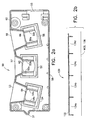
- FIG. 2a illustrates a cut-away side view of an ultrasonic detection module 50 for diagnosing printing press web breakage according to the preferred embodiment of the present invention.
- the detection module 50 may be molded plastic, and have dimensions of approximately 4.5 inches (114mm) long by approximately 1.7 inches (43mm) high.
- the detection module 50 may be adjustably located in a detector bar 130 , as illustrated in FIG. 2b, which may be extruded aluminum.
- the detector bar 130 may have a channel 132 sufficiently long to hold up to four detection modules 50 arranged in series logic in slot positions 134a, b, c and d, respectively. Stocking the detector bar with four modules 50 allows for accurate web detection at both full and half-web conditions.
- the detector module 50 has approximately the same dimensions as a Baldwin model 1127 sonic head, and thus slots 134a, b, c or d may house either detector modules 50 or prior sonic heads such as the Baldwin 1127 model.
- a flange 51 may facilitate the insertion and removal of detection module 50 to and from the detector bar 130 .
- a base side 58 of the detector module 50 fits into the detector bar channel 132 .
- the detector bar 130 is mounted to a printing press via brackets (not shown) such that a detection side 60 of the detector module 50 is oriented toward the web 136 , perpendicular to the plane of the web, nominally about 2.5 inches (64mm) from the web's surface.
- Three dimensionally-identical piezoelectric transducers 62, 64 and 66 are housed within individual transducer housings 52, 54 and 56 .
- the transducers 62, 64 and 66 may be cylindrical, the center of each transducer being approximately 1.2 inches (30mm) from its neighbor, and may be composed of a can containing a piezoceramic-driven aluminum membrane. Each can may in turn be encased in a rubber boot. Suitable transducers are commercially available from Motorola, product numbers KSN6541A and KSN6540A and from S. Square Enterprise Co., Ltd., Taiwan, Product Nos. RE455ET/R180 or RE400ET/R180. A transducer which oscillates at 45.5 kHz, 40 kHz or another frequency may be utilized.
- a transmitter transducer 62 may reside in transducer housing 52 , held in place by transducer supports 52a and 52b.
- the transmitter transducer 62 may emit a short burst of four pulses, for example 77 microseconds long, of 45.5 kHz sonic energy toward the web every 10 milliseconds.
- One receiver transducer 64 may reside in transducer housing 54 supported by transducer supports 54a and 54b, while a second receiver transducer 66 , which is approximately 2.4 inches (61mm) from the first receiver transducer, may reside in transducer housing 56 , secured by transducer supports 56a and 56b .
- the receiver transducers 64, 66 detect the presence of a return echo of the transmitted sonic energy.
- the transmitter transducer 62 is generally perpendicular to the plane of the web, while the receiver transmitters 64, 66 may be tilted toward the transmitter transducer 62 at a slight angle, for example, 10 degrees.
- Three cone-shaped horns 53, 57 and 59 which may be integral with the molded plastic of the detection module 50 , counteract cross-talk between the transducers 62, 64 and 66 .
- the center horn 57 associated with the transmitter transducer 62 is shorter than horns 53 and 59 associated with the receiver transducers 64, 66 so that, among other things, transmitted sonic energy radiates a wide beam.
- the beam width may be approximately 60 degrees, whereas past two-transducer sonic heads having angled transmitter transducers emitted total beam widths of only 45 degrees.
- the receiver transducers 64, 66 are typically immediately active upon transmission of a burst of sonic energy by the transmitter transducer 62 . To detect the presence of the web, a receiver transducer 64, 66 generally must detect a leading edge of a return echo of the transmitted sonic energy from 300 to 780 microseconds after initial transmission of the sonic energy toward the web.
- This calculation may be performed by a system controller (not shown) such as the Baldwin Web Controls model 1127 controller using well-known methods.
- the web is considered present if it is found to be within certain distances, for example, 1 to 4 inches (25-100mm) from the detection module 50 . If the web is not detected within 1 to 4 inches (25-100mm) of the module 50 , an emergency shutdown signal is sent to the printing presses (depicted in FIG. 1) by the web system controller (discussed further below).
- Connector port 55 allows the detector module 50 to be remotely connected to the system controller via a cable (not shown), which supplies communication between the detection module 50 and the system controller.
- the system controller is responsible, for example, for (1) generating control signals which cause the transmitter transducer 62 to periodically emit bursts of sonic energy, (2) accepting and analyzing the return echo signals detected by the receiver transducer 64, 66, and (3) for determining whether the web is or is not present beneath the detector module 50 based on the analysis performed on the return echo signals.
- a web is considered to be absent by the controller when there are no return echo signals from the web (within a given distance, such as 1 inch to 4 inches (25-100mm)) for a certain number of consecutive transmit signals, the number of tolerated return echo absences being dependent on web speed.
- the methods for processing return echo signals based on web speed to determine web presence or absence are well-known to those skilled in the art.
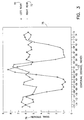
- Return echo signal strength 75 i.e., a direct current magnitude of a return echo signal
- a centerline point 73 directly beneath a transmitter transducer for both a left receiver transducer 70 and a right receiver transducer 72, the left and right receiver transducers being positioned approximately 2.4 inches (61mm) apart, as a web wrinkle with a height of 0.43 (10.92mm) inches passes from left to right under the ultrasonic detection module.
- the graph 75 demonstrates that the left and right transducer receivers in different locations from the same transmitter have signal losses (and therefore absent return echo signals) as the wrinkle changes position.
- the left receiver transducer 72 maintains a relative signal strength of about 5.5 when the wrinkle is near the left of the detection module, the left receiver transducer signal strength drops to about 1. Conversely, as the wrinkle travels toward to the right side of the detection module, the left receiver transducer maintains a signal strength of approximately 5.5, while the right receiver transducer signal strength drops to about 1.
- the loss of signal detected by the receiver transducer nearest to the wrinkle may explained by, for example, two general principles of wave mechanics.
- a rise in the web height because of the wrinkle creates an obstruction in the path of the return echo signals--the wrinkle thus blocks most of the return echo signals from being detected by the receiver transducer closest to the wrinkle.
- the wrinkle causes a phase angle of the return echo signals to shift such that signal cancellation with the transmitted sonic energy results.
- the effect of web wrinkles on the web break detection process may be reduced by comparing the return echo signal strengths detected by the left and right receiver transducers prior to the system controller performing analysis of the return echo signals. Then, only the stronger of the left or right receiver transducer signal must be analyzed by the controller to determine whether the web is or is not present beneath the detector module.
- the three-transducer detector module according to the present invention eliminates the need for parallel logic connection of detection modules. Thus, web edge tears are quickly detected.
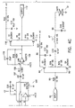
- FIG. 4 is a schematic electrical diagram of the ultrasonic detection module according to the preferred embodiment of the present invention.
- the electronics are designed to be used with a Baldwin Web Controls model 1127 system controller, which utilizes well-known methods for providing a 4-pulse signal to a transmitter transducer, and for digitally processing the return echo signals detected by a receiver transducer.
- Circuitry 80 associated with the transmitter transducer 81 of the preferred embodiment of the detection module described in connection with FIG. 2 receives an input 82 from the system controller (not shown) and is fed via resistor 83 to dual emitter followers 84, 85 .
- the dual emitter followers 84, 85, via coupling capacitor 86 drive the transmitter transducer 81 at its low impedance resonance point, series resonating with inductor 87 and capacitor 88 .
- Circuitry 90a is associated with a first receiver transducer 91a, and identical circuitry 90b is associated with a second receiver transducer 91b, both transducers 91a and 91b being constructed and oriented according to the preferred embodiment of the detection module described in connection with FIG. 2.
- the inputs from receiver transducers 91a,b are fed to capacitors 92a,b and resistors 93a,b.
- the capacitor-resistor combinations discriminate against lower frequency interference.
- Operational amplifier stages 94a,b, along with their associated capacitors 95a,b and resistors 96a,b, provide some gain along with impedance transformation.
- Stages 97a,b including operational amplifiers 98a,b and their associated components beginning with resistors 99a,b comprise two-pole bandpass filters centered at the transmitter transducer's frequency.
- Stages 97a,b also provide gain.
- the outputs of stages 97a,b serve as inputs to stages 118a,b, which provide large, adjustable gain.
- the return echo signals detected by each receiver transducer could be added together and processed by the system controller.
- the addition method is not preferred, however, because, as illustrated in FIG. 5, the signals from the left receiver transducer 70 and the right receiver transducer 72 may be out of phase. As shown, the signals are 180 degrees out of phase, so that simple addition of the signal magnitudes would be impossible, and could lead to unsatisfactory web detection.
- stages 119a,b plus 100a,b perform full-wave rectification of the signals, so that absolute magnitudes or direct current values of the return echo signals detected by each receiver transducer are obtained.
- the rectified signals represent the relative strengths of the signals.
- Components 101a,b and 102a,b provide filtering.
- the rectified and filtered signals are impedance transformed by operational amplifier stages 103a,b and their associated components. Then, each signal is fed into a comparator stage 104, which drives analog switch 105 . The analog switch 105 selects the stronger of the two signals. The strongest signal is fed to a final amplifier stage 106 via capacitor 107 and resistor 108 . Capacitor 109 provides stabilization. Stage 106 drives dual emitter followers 110, 111, the output 112 of which is capable of driving long cables (not shown) for connecting the detection module to the system controller.
Landscapes
- Chemical & Material Sciences (AREA)
- Health & Medical Sciences (AREA)
- Life Sciences & Earth Sciences (AREA)
- Immunology (AREA)
- Analytical Chemistry (AREA)
- Biochemistry (AREA)
- General Health & Medical Sciences (AREA)
- General Physics & Mathematics (AREA)
- Physics & Mathematics (AREA)
- Pathology (AREA)
- Engineering & Computer Science (AREA)
- Food Science & Technology (AREA)
- Medicinal Chemistry (AREA)
- Controlling Rewinding, Feeding, Winding, Or Abnormalities Of Webs (AREA)
- Inking, Control Or Cleaning Of Printing Machines (AREA)
- Investigating Or Analyzing Materials By The Use Of Ultrasonic Waves (AREA)
- Handling Of Sheets (AREA)
- Controlling Sheets Or Webs (AREA)
Abstract
Description
- This invention relates generally to non-contact measurement systems for monitoring a web of material, and, more particularly, to an ultrasonic apparatus and method for diagnosing printing press web breakage while minimizing the effect of web wrinkles on the detection process which utilizes an ultrasonic transmitter and at least two ultrasonic receivers.
- Measurement systems, particularly ultrasonic measurement systems, are widely used in the printing industry to monitor characteristics of a web of paper ("web") passing through machinery such as a printing press. Ultrasonic technology is popular because of its reliable operation in the often dusty and dirty printing plant environment.
- The principles of operation of ultrasonic measurement systems are well-known. When ultrasonic energy (i.e., a frequency higher than the audible range, or above 20 kHz) is incident on an object such as a web, part of the energy is reflected, part is transmitted and part is absorbed. Measuring the time between transmission of the energy and return of the reflected energy (the "return echo"), makes it possible to determine the distance from the ultrasonic transmitter and/or receiver to the web.
- One important function of an ultrasonic measurement system for a printing press is to detect web breaks by checking for the absence or presence of a web within a certain distance from the measurement system. A typical ultrasonic web break detection system generates an emergency shutdown signal if the web is determined to be absent. The web is judged to be absent when no return echo is received by an ultrasonic receiver within certain amount of time, or if the time for receipt of the return echo indicates that the web has traveled outside of acceptable tolerances. Conversely, if there is a return echo within an acceptable time, the measurement system considers the web to be present and does not generate an emergency shutdown signal.
- When a web breaks, the web is often directed back into the printing press, where it becomes entangled in the press rolls, resulting in substantial down-time and repair expenses. When a web break is detected it is often desirable to deploy a press protection device which stops the printing presses and severs and/or re-directs the web at various points. Accordingly, a false web breakage alarm could cause significant and unnecessary delay and expense.
- Two well known ultrasonic web break detection systems used in the printing industry include the sonic web break detector disclosed in U.S. Patent No. 5,036,706 to Gnuechtel et al. and the model 1127 ultrasonic web break detector manufactured by Baldwin Web Controls. Such systems detect the presence or absence of a web within certain tolerances which vary with the speed of the web.
- Web break detectors generally mount directly to a printing press, perpendicular to the plane of the web, within a few inches of the web's surface. Known web break detectors typically comprise a pair of piezoelectric transducers functioning in opposite ways, i.e., one transducer transmits ultrasonic energy at a predetermined amplitude, frequency and phase angle and a second transducer receives a return echo of the transmitted energy. The transmitter transducer and the receiver transducer together comprise a sonic head, and are typically tilted toward each other at a slight angle, for example, 5 to 10 degrees.
- The transmission and reception of sonic energy by the sonic head is typically coordinated by a controller module, which causes the transmitter to emit a short burst of sonic energy every few milliseconds and, if the web is present, looks for the receiver to detect a return echo of sonic energy within a certain time, for example 300 to 780 microseconds, after the beginning of the transmission of the energy burst.
- In addition, when the web is present, the receiver must generally show the presence of a return echo from the web for a certain number of consecutive transmit signals. The number of absent return echo signals tolerated is dependent on web speed, and decreases as web speed increases. Thus, the number of return echo absences functions as a filter which helps to ameliorate the possibility of the detection system issuing an emergency shutdown signal because of web flutter or small holes in the web.
- Further, if a web is present, the controller module may continuously monitor the strength of the return echo to determine whether the receiver transducer has become dirty--covered with ink or paper dust, for example. A two-transducer sonic head will not function properly if the receiver transducer is too dirty.
- Often, a single controller synchronizes multiple web break detection systems, each detection system having one or more sonic heads, so that the timing of sonic energy transmission and reception for each sonic head is synchronized. Synchronizing detection systems which are in close proximity to each other eliminates interference in the detection of return echoes which would result if timing were not precisely synchronized.
- Typical ultrasonic web break detection systems utilizing a single transmitter-receiver transducer pair per sonic head suffer from the problem of mistaking harmless web angles and wrinkles in the web, which cause marked degradation of the return echo signal, for actual web breaks, thereby shutting down machinery and severing and re-directing webs unnecessarily.
- Past systems have attempted to solve the false web breakage alarm problem caused by wrinkles by connecting the processed signals from two sonic heads in parallel logic, so that each sonic head must detect the absence of the web before an emergency shutdown signal is generated.
- Parallel logic connection of the sonic heads suffers from various disadvantages, however. First, space within a detection system is wasted with two sonic heads essentially functioning as one detection unit. Second, cost and complexity are increased, where one transmitter transducer and associated electronics must be utilized for each receiver transducer, then both transmitter transducers must be synchronized to prevent interference between the adjacent transducer pairs. Third, the controller module must perform the same web detection analysis for each receiver transducer input. This wastes controller inputs and increases web break detection times, thus creating the potential for more serious press jams. For example, when two sonic heads are connected in parallel, a small web tear at only one edge (i.e., under only one sonic head), often referred to as an "edge tear", will not result in press shutdown until the tear travels further across the web. This is because, when connected in parallel logic, both sonic heads must detect a web break before an emergency shutdown signal is generated.
- Embodiments of the invention enable minimisation of false web breakage alarms resulting primarily from web wrinkles and secondly from angular web distortion.
- Embodiments of the invention allow reduction of a number of components necessary to detect web breakage and prevent false web breakage alarms resulting from web wrinkles.
- Embodiments of the invention increase reliability of web breakage detection systems.
- Embodiments of the invention decrease web tear detection time.
- According to a first aspect of the present invention there is provided a method of detecting a web break, comprising: transmitting periodically a burst of energy for a period of time by a first transducer, the burst of energy being reflected off the web thereby producing an echo signal; receiving a first portion of the echo signal by a second transducer and receiving a second portion of the echo signal by a third transducer; determining a strength of the first portion of the echo signal and a strength of the second portion of the echo signal; comparing the strength of the first portion of the echo signal with the strength of the second portion of the echo signal to determine which portion is stronger; analyzing the stronger portion of the echo signal to determine the presence of a web break.
- According to a second aspect of the present invention there is provided a method of detecting a web break, comprising: transmitting periodically a burst of energy for a period of time by a first transducer, the burst of energy being reflected off the web thereby producing an echo signal; receiving a first portion of the echo signal by a second transducer; and receiving a second portion of the echo signal by a third transducer; and adding the first portion of the echo signal and the second portion of the echo signal to arrive at a resultant signal; and analysing the resultant signal to determine the presence of a web break.
- According to a third aspect of the present invention there is provided an apparatus for detecting a web break, comprising: a first transducer for periodically emitting a burst of energy for a period of time, the burst of energy being reflected off the web thereby producing an echo signal; a second transducer adapted to receive a first portion of the echo signal; a third transducer adapted to receive a second portion of the echo signal; and a system controller disposed in communication with the second and third transducers for receiving and comparing said first and second portions of the echo signal to determine the stronger portion of the echo signal and, for determining the presence of a web break from the analysis of said stronger portion of the echo signal.
- According to a fourth aspect of the present invention there is provided an apparatus for detecting a web break, comprising: a first transducer for periodically emitting a burst of energy for a period of time, the burst of energy being reflected off the web thereby producing an echo signal; a second transducer adapted to receive a first portion of the echo signal; a third transducer adapted to receive a second portion of the echo signal; and a system controller disposed in communication with the second and third transducers for receiving said first and second portions of the echo signal, for adding the first and second portions of the echo signal to arrive at a resultant signal, and for analysing the resultant signal to determine the presence of a web break.
- Further aspects of the invention and preferred features are set out in the dependent claims.
- Exemplary embodiments of the invention will now be described with reference to the accompanying drawings in which:
- Fig. 1 illustrates a typical multiple printing unit heat set press system.
- Fig. 2a illustrates a cut-away side view of an ultrasonic detection module for diagnosing printing press web breakage according to the preferred embodiment of the present invention.
- FIG. 2b illustrates a cut-away side view of a detector bar for housing up to four detection modules according to the preferred embodiment of the present invention.
- FIG. 3 illustrates the principle of operation of the ultrasonic detection module for diagnosing printing press web breakage while reducing false web break alarms according to the preferred embodiment of the present invention.
- FIG. 4 is a schematic electrical diagram of the ultrasonic detection module according to the preferred embodiment of the present invention.
- FIG. 5 illustrates the difference in phase angle of a return echo signal received by a left receiver transducer and a return echo received by a right receiver transducer of a detection module according to the preferred embodiment of the present invention.
-
- Turning now to the drawings, wherein like numerals designate like components, FIG. 1 illustrates a typical multiple printing unit heat set press system. As shown, the press may include
multiple printing units 10A-10D, each having one or more blankedimpression cylinder combinations 5 employed in the printing process. When theprinting units 10A-10D are running, theblanked cylinders 5 feed acontinuous paper web 30 through theprinting units 10A-10D, from an infeedunit 2 upstream from theprinting units 10A-10D and then through aweb dryer unit 35 and achill unit 40 downstream of theprinting units 10A-10D. - Web
break detection systems 15, which may be ultrasonic systems, are located at various points in the system aboveweb 30 to detect when theweb 30 breaks. As shown, aweb break 42 has occurred in thedryer unit 35. - FIG. 2a illustrates a cut-away side view of an
ultrasonic detection module 50 for diagnosing printing press web breakage according to the preferred embodiment of the present invention. Thedetection module 50 may be molded plastic, and have dimensions of approximately 4.5 inches (114mm) long by approximately 1.7 inches (43mm) high. - The
detection module 50 may be adjustably located in adetector bar 130, as illustrated in FIG. 2b, which may be extruded aluminum. Thedetector bar 130 may have achannel 132 sufficiently long to hold up to fourdetection modules 50 arranged in series logic inslot positions 134a, b, c and d, respectively. Stocking the detector bar with fourmodules 50 allows for accurate web detection at both full and half-web conditions. Thedetector module 50 has approximately the same dimensions as a Baldwin model 1127 sonic head, and thusslots 134a, b, c or d may house eitherdetector modules 50 or prior sonic heads such as the Baldwin 1127 model. - Referring again to FIG. 2a, a
flange 51 may facilitate the insertion and removal ofdetection module 50 to and from thedetector bar 130. Abase side 58 of thedetector module 50 fits into thedetector bar channel 132. Thedetector bar 130 is mounted to a printing press via brackets (not shown) such that adetection side 60 of thedetector module 50 is oriented toward theweb 136, perpendicular to the plane of the web, nominally about 2.5 inches (64mm) from the web's surface. Three dimensionally-identicalpiezoelectric transducers individual transducer housings transducers - A
transmitter transducer 62 may reside intransducer housing 52, held in place by transducer supports 52a and 52b. Thetransmitter transducer 62 may emit a short burst of four pulses, for example 77 microseconds long, of 45.5 kHz sonic energy toward the web every 10 milliseconds. - One
receiver transducer 64 may reside intransducer housing 54 supported by transducer supports 54a and 54b, while asecond receiver transducer 66, which is approximately 2.4 inches (61mm) from the first receiver transducer, may reside intransducer housing 56, secured by transducer supports 56a and 56b. Thereceiver transducers - The
transmitter transducer 62 is generally perpendicular to the plane of the web, while thereceiver transmitters transmitter transducer 62 at a slight angle, for example, 10 degrees. Three cone-shapedhorns detection module 50, counteract cross-talk between thetransducers center horn 57 associated with thetransmitter transducer 62 is shorter thanhorns receiver transducers - The
receiver transducers transmitter transducer 62. To detect the presence of the web, areceiver transducer - Measuring the amount of time elapsed between initial transmission of sonic energy by the
transmitter transducer 62 and detection of the leading edge of the return echo by thereceiver transducer detection module 50. This calculation may be performed by a system controller (not shown) such as the Baldwin Web Controls model 1127 controller using well-known methods. The web is considered present if it is found to be within certain distances, for example, 1 to 4 inches (25-100mm) from thedetection module 50. If the web is not detected within 1 to 4 inches (25-100mm) of themodule 50, an emergency shutdown signal is sent to the printing presses (depicted in FIG. 1) by the web system controller (discussed further below). -
Connector port 55 allows thedetector module 50 to be remotely connected to the system controller via a cable (not shown), which supplies communication between thedetection module 50 and the system controller. - The system controller is responsible, for example, for (1) generating control signals which cause the
transmitter transducer 62 to periodically emit bursts of sonic energy, (2) accepting and analyzing the return echo signals detected by thereceiver transducer detector module 50 based on the analysis performed on the return echo signals. - A web is considered to be absent by the controller when there are no return echo signals from the web (within a given distance, such as 1 inch to 4 inches (25-100mm)) for a certain number of consecutive transmit signals, the number of tolerated return echo absences being dependent on web speed. The methods for processing return echo signals based on web speed to determine web presence or absence are well-known to those skilled in the art.
- The frequency of false web break alarms which occur because of web wrinkles is reduced by using the preferred embodiment of the detection-module constructed and oriented as described in connection with FIG. 2, the principle of operation of which is graphically illustrated in FIG. 3. Return
echo signal strength 75, i.e., a direct current magnitude of a return echo signal, is plotted against wrinkle distance from acenterline point 73 directly beneath a transmitter transducer, for both aleft receiver transducer 70 and aright receiver transducer 72, the left and right receiver transducers being positioned approximately 2.4 inches (61mm) apart, as a web wrinkle with a height of 0.43 (10.92mm) inches passes from left to right under the ultrasonic detection module. - The
graph 75 demonstrates that the left and right transducer receivers in different locations from the same transmitter have signal losses (and therefore absent return echo signals) as the wrinkle changes position. - For example, while the
right receiver transducer 72 maintains a relative signal strength of about 5.5 when the wrinkle is near the left of the detection module, the left receiver transducer signal strength drops to about 1. Conversely, as the wrinkle travels toward to the right side of the detection module, the left receiver transducer maintains a signal strength of approximately 5.5, while the right receiver transducer signal strength drops to about 1. - A similar situation results when the web is tilted side-to-side, and, as will be appreciated by one skilled in the art, the principles of the present invention which apply to reducing false web break alarms resulting from web wrinkles are also applicable to reducing the false alarms which occur because of web angles.
- The loss of signal detected by the receiver transducer nearest to the wrinkle may explained by, for example, two general principles of wave mechanics. First, a rise in the web height because of the wrinkle creates an obstruction in the path of the return echo signals--the wrinkle thus blocks most of the return echo signals from being detected by the receiver transducer closest to the wrinkle. Second, the wrinkle causes a phase angle of the return echo signals to shift such that signal cancellation with the transmitted sonic energy results.
- Thus, it is seen that the effect of web wrinkles on the web break detection process may be reduced by comparing the return echo signal strengths detected by the left and right receiver transducers prior to the system controller performing analysis of the return echo signals. Then, only the stronger of the left or right receiver transducer signal must be analyzed by the controller to determine whether the web is or is not present beneath the detector module.
- The use of two receiver transducers in the manner described herein increases detector module reliability over prior systems having one transmitter transducer and one receiver transducer. For example, one receiver transducer which breaks or becomes blocked by dirt will not affect the continued operation of a detector module according to the present invention because a second receiver transducer will continue to detect web breaks in a manner comparable to prior two-transducer systems.
- As will further be recognized by one skilled in the art, the three-transducer detector module according to the present invention eliminates the need for parallel logic connection of detection modules. Thus, web edge tears are quickly detected.
- FIG. 4 is a schematic electrical diagram of the ultrasonic detection module according to the preferred embodiment of the present invention. The electronics are designed to be used with a Baldwin Web Controls model 1127 system controller, which utilizes well-known methods for providing a 4-pulse signal to a transmitter transducer, and for digitally processing the return echo signals detected by a receiver transducer.
-
Circuitry 80 associated with thetransmitter transducer 81 of the preferred embodiment of the detection module described in connection with FIG. 2 receives aninput 82 from the system controller (not shown) and is fed viaresistor 83 todual emitter followers dual emitter followers transmitter transducer 81 at its low impedance resonance point, series resonating withinductor 87 andcapacitor 88. -
Circuitry 90a is associated with afirst receiver transducer 91a, andidentical circuitry 90b is associated with asecond receiver transducer 91b, bothtransducers - The inputs from
receiver transducers 91a,b are fed tocapacitors 92a,b andresistors 93a,b. The capacitor-resistor combinations discriminate against lower frequency interference.Operational amplifier stages 94a,b, along with their associatedcapacitors 95a,b andresistors 96a,b, provide some gain along with impedance transformation.Stages 97a,b including operational amplifiers 98a,b and their associated components beginning withresistors 99a,b comprise two-pole bandpass filters centered at the transmitter transducer's frequency.Stages 97a,b also provide gain. The outputs ofstages 97a,b serve as inputs tostages 118a,b, which provide large, adjustable gain. - At this point, the return echo signals detected by each receiver transducer could be added together and processed by the system controller. The addition method is not preferred, however, because, as illustrated in FIG. 5, the signals from the
left receiver transducer 70 and theright receiver transducer 72 may be out of phase. As shown, the signals are 180 degrees out of phase, so that simple addition of the signal magnitudes would be impossible, and could lead to unsatisfactory web detection. - Thus, it is preferred that
stages 119a,b plus 100a,b perform full-wave rectification of the signals, so that absolute magnitudes or direct current values of the return echo signals detected by each receiver transducer are obtained. The rectified signals represent the relative strengths of the signals.Components 101a,b and 102a,b provide filtering. - The rectified and filtered signals are impedance transformed by
operational amplifier stages 103a,b and their associated components. Then, each signal is fed into acomparator stage 104, which drivesanalog switch 105. Theanalog switch 105 selects the stronger of the two signals. The strongest signal is fed to afinal amplifier stage 106 viacapacitor 107 andresistor 108. Capacitor 109 provides stabilization.Stage 106 drivesdual emitter followers output 112 of which is capable of driving long cables (not shown) for connecting the detection module to the system controller.
Claims (21)
- A method of detecting a web break, comprising:transmitting periodically a burst of energy for a period of time by a first transducer (62), the burst of energy being reflected off the web (136) thereby producing an echo signal;receiving a first portion of the echo signal by a second transducer (64) and receiving a second portion of the echo signal by a third transducer (66);determining a strength of the first portion of the echo signal and a strength of the second portion of the echo signal;comparing the strength of the first portion of the echo signal with the strength of the second portion of the echo signal to determine which portion is stronger;analyzing the stronger portion of the echo signal to determine the presence of a web break.
- The method according to claim 1, further comprising the step of sending an emergency shutdown signal to a machine feeding the web (136) if the analysis determines that a web break is present.
- The method according to claim 1 or 2, further comprising the steps of:calculating an amount of time elapsed between transmission of the burst of energy and receipt of the portion of the echo signal by the transducer which received the strongest echo signal;determining a position of the web; anddetecting whether the web position is acceptable.
- A method of detecting a web break, comprising:transmitting periodically a burst of energy for a period of time by a first transducer (62), the burst of energy being reflected off the web (136) thereby producing an echo signal;receiving a first portion of the echo signal by a second transducer (64); andreceiving a second portion of the echo signal by a third transducer (66); andadding the first portion of the echo signal and the second portion of the echo signal to arrive at a resultant signal; andanalysing the resultant signal to determine the presence of a web break.
- A method according to any of the preceding claims, wherein said first transducer (62) is located perpendicular to a plane of the web.
- A method according to any of the preceding claims, wherein the first transducer is located 6,35 cm (2,5 inches) from a normal operating position of the web.
- An apparatus for detecting a web break, comprising:a first transducer (62) for periodically emitting a burst of energy for a period of time, the burst of energy being reflected off the web (136) thereby producing an echo signal;a second transducer (64) adapted to receive a first portion of the echo signal;a third transducer (66) adapted to receive a second portion of the echo signal; anda system controller disposed in communication with the second and third transducers (64, 66) for receiving and comparing said first and second portions of the echo signal to determine the stronger portion of the echo signal, and for determining the presence of a web break from the analysis of said stronger portion of the echo signal.
- An apparatus for detecting a web break, comprising:a first transducer (62) for periodically emitting a burst of energy for a period of time, the burst of energy being reflected off the web (136) thereby producing an echo signal;a second transducer (64) adapted to receive a first portion of the echo signal;a third transducer (66) adapted to receive a second portion of the echo signal; anda system controller disposed in communication with the second and third transducers (64, 66) for receiving said first and second portions of the echo signal, for adding the first and second portions of the echo signal to arrive at a resultant signal, and for analysing the resultant signal to determine the presence of a web break.
- The apparatus according to claim 7 or 8, wherein the first transducer (62) comprises a piezoelectric transducer and/or said second and third transducers (64,66) comprise piezoelectric transducers.
- The apparatus according to claim 7 or 8, wherein the burst of energy emitted by the first transducer (62) has a frequency of 45.5 Hz.
- The apparatus according to claim 10, wherein the burst of energy emitted by the first transducer (62) lasts for seventy seven microseconds.
- The apparatus according to claim 10 or 11, wherein the burst of energy emitted by the first transducer (62) is repeated every ten milliseconds.
- The apparatus according to claims 7 or 8, wherein the second and third transducers (64, 66) are angled toward the first transducer (62) by ten degrees.
- The apparatus according to claim 7 or 8, further comprising:a housing for maintaining the first, second and third transducers (62, 64, 66) in a fixed relationship relative to one another.
- The apparatus according to claim 14, wherein the housing comprises molded plastic.
- The apparatus [in] according to claim 14, wherein the housing further comprises:a first conical cavity (57) associated with an emission side of the first transducer (62);a second conical cavity (53) associated with a reception side of the second transducer (64); anda third conical cavity (59) associated with a reception side of the third transducer (66), wherein the conical cavities (53, 57, 59) are arranged to reduce signal interference between the transducers (62, 64, 66) and shape their ultrasonic beams.
- The apparatus in claim 16, wherein the first conical cavity (57) associated with the first transducer (62) is shorter than the conical cavities (53,59) associated with the second (64) and third (66) transducers, so that the burst of energy emitted by the first transducer (62) is wide enough that the portions of the echo signal are received by both the second and the third transducers (64, 66) simultaneously.
- The apparatus according to claim 7, wherein the system controller is in communication with the first, second and third transducers (62, 64, 66) for calculating an amount of time elapsed between transmission of the burst of energy and reception of the strongest portion of the echo signal.
- The apparatus according to claim 7 or 8, comprising a means for transmitting to the system controller a signal comprising a portion of the echo signal detected by any of the receivers.
- The apparatus according to claim 7, wherein the system controller calculates an amount of time elapsed between transmission of the burst of sonic energy and receipt of the signal comprising the strongest portion of the echo signal detected by one of the receivers, to determine a position of the web, and to detect whether the web position is acceptable.
- The apparatus according to claim 7, wherein the system controller comprises a comparator.
Applications Claiming Priority (2)
| Application Number | Priority Date | Filing Date | Title |
|---|---|---|---|
| US517333 | 1995-08-21 | ||
| US08/517,333 US5652388A (en) | 1995-08-21 | 1995-08-21 | Apparatus and method for detecting printing press web breakage |
Publications (2)
| Publication Number | Publication Date |
|---|---|
| EP0759554A1 EP0759554A1 (en) | 1997-02-26 |
| EP0759554B1 true EP0759554B1 (en) | 2004-11-10 |
Family
ID=24059383
Family Applications (1)
| Application Number | Title | Priority Date | Filing Date |
|---|---|---|---|
| EP96306044A Expired - Lifetime EP0759554B1 (en) | 1995-08-21 | 1996-08-19 | Apparatus and method for detecting printing press web breakage |
Country Status (7)
| Country | Link |
|---|---|
| US (1) | US5652388A (en) |
| EP (1) | EP0759554B1 (en) |
| JP (1) | JPH09132345A (en) |
| CN (1) | CN1115558C (en) |
| AT (1) | ATE282202T1 (en) |
| CA (1) | CA2183408A1 (en) |
| DE (1) | DE69633814T2 (en) |
Families Citing this family (15)
| Publication number | Priority date | Publication date | Assignee | Title |
|---|---|---|---|---|
| US6098063A (en) * | 1994-02-15 | 2000-08-01 | R. R. Donnelley & Sons | Device and method for identifying causes of web breaks in a printing system on web manufacturing attributes |
| US5694524A (en) * | 1994-02-15 | 1997-12-02 | R. R. Donnelley & Sons Company | System and method for identifying conditions leading to a particular result in a multi-variant system |
| US5850184A (en) * | 1997-06-25 | 1998-12-15 | Cobra Machine Tool Co., Inc. | Ultrasonic tool confirmation sensor |
| DE19734137C2 (en) * | 1997-08-07 | 2001-07-12 | Baldwin Grafotec Gmbh | Device for preventing printing unit damage |
| US5942689A (en) * | 1997-10-03 | 1999-08-24 | General Electric Company | System and method for predicting a web break in a paper machine |
| US6405140B1 (en) | 1999-09-15 | 2002-06-11 | General Electric Company | System and method for paper web time-break prediction |
| US6466877B1 (en) | 1999-09-15 | 2002-10-15 | General Electric Company | Paper web breakage prediction using principal components analysis and classification and regression trees |
| US6498993B1 (en) | 2000-05-30 | 2002-12-24 | Gen Electric | Paper web breakage prediction using bootstrap aggregation of classification and regression trees |
| JP3673777B2 (en) * | 2001-08-21 | 2005-07-20 | キヤノン株式会社 | Signal output device, sheet material type discrimination device, and image forming device |
| US6763763B2 (en) * | 2001-11-20 | 2004-07-20 | Discover Graphics, Inc. | Web press rotary equipment protection system |
| US7415881B2 (en) * | 2004-08-19 | 2008-08-26 | Fife Corporation | Ultrasonic sensor system for web-guiding apparatus |
| WO2007073340A1 (en) * | 2005-12-22 | 2007-06-28 | Stora Enso Ab | A method and a system for monitoring structural changes of a fiber web |
| JP4960466B2 (en) * | 2010-03-18 | 2012-06-27 | 株式会社東芝 | Paper sheet processing equipment |
| US9415963B2 (en) | 2013-01-30 | 2016-08-16 | Fife Corporation | Sensor controller for interpreting natural interaction sensor for web handling |
| EP2826626B1 (en) * | 2013-07-15 | 2016-01-20 | Goss Contiweb B.V. | Web break analysis system |
Family Cites Families (10)
| Publication number | Priority date | Publication date | Assignee | Title |
|---|---|---|---|---|
| GB1385184A (en) * | 1971-02-26 | 1975-02-26 | British Iron Steel Research | Method and apparatus for testing moving material |
| FI45799C (en) * | 1971-03-23 | 1972-09-11 | Valmet Oy | A method for determining the orientation of paper or a similar fiber by means of light reflected from paper. |
| FR2199887A5 (en) * | 1972-08-16 | 1974-04-12 | Shraiber David | |
| EP0098115A1 (en) * | 1982-06-28 | 1984-01-11 | De La Rue Systems Limited | Detecting the condition of a sheet or web |
| US4496428A (en) * | 1982-09-23 | 1985-01-29 | Champion International Corporation | Apparatus for paper tension control by measuring the frequency and flutter of a web |
| DE3424652C2 (en) * | 1984-07-04 | 1993-11-11 | Gao Ges Automation Org | Device for the dynamic non-contact determination of the local basis weight of sheet material |
| US5280724A (en) * | 1989-06-22 | 1994-01-25 | Nissan Motor Co., Ltd. | Ultrasonic inspection method for detecting defects in solid objects |
| US5036706A (en) * | 1989-08-08 | 1991-08-06 | Web Printing Controls Co., Inc. | Sonic web break detector |
| FR2661749B1 (en) * | 1990-05-02 | 1994-04-15 | Centre Tech Ind Papiers Cartons | METHOD AND DEVICE FOR DETERMINING THE COEFFICIENT OF ELASTICITY OF A NON-RIGID THROUGHPUT MATERIAL. |
| DE4106901C2 (en) * | 1991-03-05 | 1994-05-26 | Kotterer Grafotec | Method and device for monitoring a web |
-
1995
- 1995-08-21 US US08/517,333 patent/US5652388A/en not_active Expired - Fee Related
-
1996
- 1996-08-14 JP JP8233665A patent/JPH09132345A/en active Pending
- 1996-08-15 CA CA002183408A patent/CA2183408A1/en not_active Abandoned
- 1996-08-19 DE DE69633814T patent/DE69633814T2/en not_active Expired - Lifetime
- 1996-08-19 AT AT96306044T patent/ATE282202T1/en not_active IP Right Cessation
- 1996-08-19 EP EP96306044A patent/EP0759554B1/en not_active Expired - Lifetime
- 1996-08-21 CN CN96119817.6A patent/CN1115558C/en not_active Expired - Fee Related
Also Published As
| Publication number | Publication date |
|---|---|
| JPH09132345A (en) | 1997-05-20 |
| DE69633814T2 (en) | 2005-03-17 |
| CN1115558C (en) | 2003-07-23 |
| CA2183408A1 (en) | 1997-02-22 |
| MX9603525A (en) | 1997-07-31 |
| EP0759554A1 (en) | 1997-02-26 |
| DE69633814D1 (en) | 2004-12-16 |
| US5652388A (en) | 1997-07-29 |
| CN1178323A (en) | 1998-04-08 |
| ATE282202T1 (en) | 2004-11-15 |
Similar Documents
| Publication | Publication Date | Title |
|---|---|---|
| US5652388A (en) | Apparatus and method for detecting printing press web breakage | |
| US4901292A (en) | Method for the position detection of the strip edge of a material web | |
| US5515341A (en) | Proximity sensor utilizing polymer piezoelectric film | |
| US7025348B2 (en) | Method and apparatus for detection of multiple documents in a document scanner using multiple ultrasonic sensors | |
| KR20090122983A (en) | Method and apparatus for detecting corrugator and paper joints thereof | |
| KR900006580A (en) | Method and apparatus for recognizing unnecessary substance in fiber | |
| US5479825A (en) | Transducers for transmitting and/or receiving ultrasonic energy | |
| CA2334974A1 (en) | Measuring the speed of sound of a gas | |
| JPH09132345A5 (en) | ||
| US5036706A (en) | Sonic web break detector | |
| CA2111299A1 (en) | Method and Device for Monitoring an Edge of a Moving Web | |
| US5421102A (en) | Non-contacting drying system | |
| CA1256976A (en) | Self-diagnostic ultrasonic intrusion detection system | |
| JP3890766B2 (en) | Double feed detection device for sheet material using ultrasonic waves | |
| JPH02156391A (en) | Method and apparatus for counting flat product within flake | |
| JP4688497B2 (en) | Method and apparatus for identifying an opening tape on a material strip | |
| MXPA96003525A (en) | Apparatus and method for detecting rupture of the continuous paper roll in a print press | |
| US5737238A (en) | Method and apparatus for ply discontinuity detection | |
| KR19990044446A (en) | Subspace Detection and Monitoring Method | |
| CA2234905A1 (en) | Method and assembly for monitoring a predetermined level in a container | |
| DE19701644A1 (en) | Sheet supply control unit for industrial printing machine | |
| JPH0672591A (en) | Supersonic wave type two sheet detection method | |
| JP2000025988A (en) | Method of detecting double feed of sheet material using ultrasonic waves | |
| US4513404A (en) | Acoustic reflectometer for sheet feed sensing | |
| JP2000185629A (en) | Monitoring system for vehicle interior |
Legal Events
| Date | Code | Title | Description |
|---|---|---|---|
| PUAI | Public reference made under article 153(3) epc to a published international application that has entered the european phase |
Free format text: ORIGINAL CODE: 0009012 |
|
| AK | Designated contracting states |
Kind code of ref document: A1 Designated state(s): AT BE CH DE DK ES FI FR GB GR IE IT LI LU MC NL PT SE |
|
| 17P | Request for examination filed |
Effective date: 19970826 |
|
| 17Q | First examination report despatched |
Effective date: 20010706 |
|
| GRAP | Despatch of communication of intention to grant a patent |
Free format text: ORIGINAL CODE: EPIDOSNIGR1 |
|
| GRAS | Grant fee paid |
Free format text: ORIGINAL CODE: EPIDOSNIGR3 |
|
| GRAA | (expected) grant |
Free format text: ORIGINAL CODE: 0009210 |
|
| AK | Designated contracting states |
Kind code of ref document: B1 Designated state(s): AT BE CH DE DK ES FI FR GB GR IE IT LI LU MC NL PT SE |
|
| PG25 | Lapsed in a contracting state [announced via postgrant information from national office to epo] |
Ref country code: NL Free format text: LAPSE BECAUSE OF FAILURE TO SUBMIT A TRANSLATION OF THE DESCRIPTION OR TO PAY THE FEE WITHIN THE PRESCRIBED TIME-LIMIT Effective date: 20041110 Ref country code: LI Free format text: LAPSE BECAUSE OF FAILURE TO SUBMIT A TRANSLATION OF THE DESCRIPTION OR TO PAY THE FEE WITHIN THE PRESCRIBED TIME-LIMIT Effective date: 20041110 Ref country code: IT Free format text: LAPSE BECAUSE OF FAILURE TO SUBMIT A TRANSLATION OF THE DESCRIPTION OR TO PAY THE FEE WITHIN THE PRE;WARNING: LAPSES OF ITALIAN PATENTS WITH EFFECTIVE DATE BEFORE 2007 MAY HAVE OCCURRED AT ANY TIME BEFORE 2007. THE CORRECT EFFECTIVE DATE MAY BE DIFFERENT FROM THE ONE RECORDED.SCRIBED TIME-LIMIT Effective date: 20041110 Ref country code: FR Free format text: LAPSE BECAUSE OF NON-PAYMENT OF DUE FEES Effective date: 20041110 Ref country code: FI Free format text: LAPSE BECAUSE OF FAILURE TO SUBMIT A TRANSLATION OF THE DESCRIPTION OR TO PAY THE FEE WITHIN THE PRESCRIBED TIME-LIMIT Effective date: 20041110 Ref country code: CH Free format text: LAPSE BECAUSE OF FAILURE TO SUBMIT A TRANSLATION OF THE DESCRIPTION OR TO PAY THE FEE WITHIN THE PRESCRIBED TIME-LIMIT Effective date: 20041110 Ref country code: BE Free format text: LAPSE BECAUSE OF FAILURE TO SUBMIT A TRANSLATION OF THE DESCRIPTION OR TO PAY THE FEE WITHIN THE PRESCRIBED TIME-LIMIT Effective date: 20041110 Ref country code: AT Free format text: LAPSE BECAUSE OF FAILURE TO SUBMIT A TRANSLATION OF THE DESCRIPTION OR TO PAY THE FEE WITHIN THE PRESCRIBED TIME-LIMIT Effective date: 20041110 |
|
| REG | Reference to a national code |
Ref country code: GB Ref legal event code: FG4D |
|
| REG | Reference to a national code |
Ref country code: CH Ref legal event code: EP |
|
| REG | Reference to a national code |
Ref country code: IE Ref legal event code: FG4D |
|
| REF | Corresponds to: |
Ref document number: 69633814 Country of ref document: DE Date of ref document: 20041216 Kind code of ref document: P |
|
| PG25 | Lapsed in a contracting state [announced via postgrant information from national office to epo] |
Ref country code: SE Free format text: LAPSE BECAUSE OF FAILURE TO SUBMIT A TRANSLATION OF THE DESCRIPTION OR TO PAY THE FEE WITHIN THE PRESCRIBED TIME-LIMIT Effective date: 20050210 Ref country code: GR Free format text: LAPSE BECAUSE OF FAILURE TO SUBMIT A TRANSLATION OF THE DESCRIPTION OR TO PAY THE FEE WITHIN THE PRESCRIBED TIME-LIMIT Effective date: 20050210 Ref country code: DK Free format text: LAPSE BECAUSE OF FAILURE TO SUBMIT A TRANSLATION OF THE DESCRIPTION OR TO PAY THE FEE WITHIN THE PRESCRIBED TIME-LIMIT Effective date: 20050210 |
|
| PG25 | Lapsed in a contracting state [announced via postgrant information from national office to epo] |
Ref country code: ES Free format text: LAPSE BECAUSE OF FAILURE TO SUBMIT A TRANSLATION OF THE DESCRIPTION OR TO PAY THE FEE WITHIN THE PRESCRIBED TIME-LIMIT Effective date: 20050221 |
|
| NLV1 | Nl: lapsed or annulled due to failure to fulfill the requirements of art. 29p and 29m of the patents act | ||
| REG | Reference to a national code |
Ref country code: CH Ref legal event code: PL |
|
| PG25 | Lapsed in a contracting state [announced via postgrant information from national office to epo] |
Ref country code: LU Free format text: LAPSE BECAUSE OF NON-PAYMENT OF DUE FEES Effective date: 20050819 Ref country code: IE Free format text: LAPSE BECAUSE OF NON-PAYMENT OF DUE FEES Effective date: 20050819 Ref country code: GB Free format text: LAPSE BECAUSE OF NON-PAYMENT OF DUE FEES Effective date: 20050819 |
|
| PG25 | Lapsed in a contracting state [announced via postgrant information from national office to epo] |
Ref country code: MC Free format text: LAPSE BECAUSE OF NON-PAYMENT OF DUE FEES Effective date: 20050831 |
|
| PLBE | No opposition filed within time limit |
Free format text: ORIGINAL CODE: 0009261 |
|
| STAA | Information on the status of an ep patent application or granted ep patent |
Free format text: STATUS: NO OPPOSITION FILED WITHIN TIME LIMIT |
|
| 26N | No opposition filed |
Effective date: 20050811 |
|
| EN | Fr: translation not filed | ||
| EN | Fr: translation not filed | ||
| GBPC | Gb: european patent ceased through non-payment of renewal fee |
Effective date: 20050819 |
|
| REG | Reference to a national code |
Ref country code: IE Ref legal event code: MM4A |
|
| PG25 | Lapsed in a contracting state [announced via postgrant information from national office to epo] |
Ref country code: PT Free format text: LAPSE BECAUSE OF NON-PAYMENT OF DUE FEES Effective date: 20050410 |
|
| PGFP | Annual fee paid to national office [announced via postgrant information from national office to epo] |
Ref country code: DE Payment date: 20090814 Year of fee payment: 14 |
|
| REG | Reference to a national code |
Ref country code: DE Ref legal event code: R119 Ref document number: 69633814 Country of ref document: DE Effective date: 20110301 |
|
| PG25 | Lapsed in a contracting state [announced via postgrant information from national office to epo] |
Ref country code: DE Free format text: LAPSE BECAUSE OF NON-PAYMENT OF DUE FEES Effective date: 20110301 |