EP0759400A2 - Collapsible container - Google Patents
Collapsible container Download PDFInfo
- Publication number
- EP0759400A2 EP0759400A2 EP96305602A EP96305602A EP0759400A2 EP 0759400 A2 EP0759400 A2 EP 0759400A2 EP 96305602 A EP96305602 A EP 96305602A EP 96305602 A EP96305602 A EP 96305602A EP 0759400 A2 EP0759400 A2 EP 0759400A2
- Authority
- EP
- European Patent Office
- Prior art keywords
- container according
- container
- base
- intermediate member
- formations
- Prior art date
- Legal status (The legal status is an assumption and is not a legal conclusion. Google has not performed a legal analysis and makes no representation as to the accuracy of the status listed.)
- Granted
Links
Images


Classifications
-
- B—PERFORMING OPERATIONS; TRANSPORTING
- B65—CONVEYING; PACKING; STORING; HANDLING THIN OR FILAMENTARY MATERIAL
- B65D—CONTAINERS FOR STORAGE OR TRANSPORT OF ARTICLES OR MATERIALS, e.g. BAGS, BARRELS, BOTTLES, BOXES, CANS, CARTONS, CRATES, DRUMS, JARS, TANKS, HOPPERS, FORWARDING CONTAINERS; ACCESSORIES, CLOSURES, OR FITTINGS THEREFOR; PACKAGING ELEMENTS; PACKAGES
- B65D11/00—Containers having bodies formed by interconnecting or uniting two or more rigid, or substantially rigid, components made wholly or mainly of plastics material
- B65D11/18—Containers having bodies formed by interconnecting or uniting two or more rigid, or substantially rigid, components made wholly or mainly of plastics material collapsible, i.e. with walls hinged together or detachably connected
- B65D11/1866—Containers having bodies formed by interconnecting or uniting two or more rigid, or substantially rigid, components made wholly or mainly of plastics material collapsible, i.e. with walls hinged together or detachably connected with detachable components
- B65D11/1873—Containers having bodies formed by interconnecting or uniting two or more rigid, or substantially rigid, components made wholly or mainly of plastics material collapsible, i.e. with walls hinged together or detachably connected with detachable components all walls are detached from each other to collapse the container
-
- B—PERFORMING OPERATIONS; TRANSPORTING
- B65—CONVEYING; PACKING; STORING; HANDLING THIN OR FILAMENTARY MATERIAL
- B65D—CONTAINERS FOR STORAGE OR TRANSPORT OF ARTICLES OR MATERIALS, e.g. BAGS, BARRELS, BOTTLES, BOXES, CANS, CARTONS, CRATES, DRUMS, JARS, TANKS, HOPPERS, FORWARDING CONTAINERS; ACCESSORIES, CLOSURES, OR FITTINGS THEREFOR; PACKAGING ELEMENTS; PACKAGES
- B65D11/00—Containers having bodies formed by interconnecting or uniting two or more rigid, or substantially rigid, components made wholly or mainly of plastics material
- B65D11/18—Containers having bodies formed by interconnecting or uniting two or more rigid, or substantially rigid, components made wholly or mainly of plastics material collapsible, i.e. with walls hinged together or detachably connected
- B65D11/1833—Containers having bodies formed by interconnecting or uniting two or more rigid, or substantially rigid, components made wholly or mainly of plastics material collapsible, i.e. with walls hinged together or detachably connected whereby all side walls are hingedly connected to the base panel
-
- B—PERFORMING OPERATIONS; TRANSPORTING
- B65—CONVEYING; PACKING; STORING; HANDLING THIN OR FILAMENTARY MATERIAL
- B65D—CONTAINERS FOR STORAGE OR TRANSPORT OF ARTICLES OR MATERIALS, e.g. BAGS, BARRELS, BOTTLES, BOXES, CANS, CARTONS, CRATES, DRUMS, JARS, TANKS, HOPPERS, FORWARDING CONTAINERS; ACCESSORIES, CLOSURES, OR FITTINGS THEREFOR; PACKAGING ELEMENTS; PACKAGES
- B65D21/00—Nestable, stackable or joinable containers; Containers of variable capacity
- B65D21/02—Containers specially shaped, or provided with fittings or attachments, to facilitate nesting, stacking, or joining together
- B65D21/0209—Containers specially shaped, or provided with fittings or attachments, to facilitate nesting, stacking, or joining together stackable or joined together one-upon-the-other in the upright or upside-down position
- B65D21/0212—Containers presenting local stacking elements protruding from the upper or lower edge of a side wall, e.g. handles, lugs, ribs, grooves
Definitions
- the present invention relates to collapsible containers.
- Containers which can collapse to a more compact form when not in use are desirable for a number of situations, such as delivery of retail goods.
- Containers loaded with retail goods can be transported to the retailer, emptied, collapsed and then returned in their collapsed condition. This makes return transport easier by minimising the volume to be transported.
- the invention provides a collapsible container comprising a base, at least one side wall which may move to a stowed position when the container is not in use, an intermediate member, hinge means connecting the intermediate member with a first one of the side wall and the base, and attachment means operable to attach the intermediate member to the second one of the side wall and the base, the intermediate member and the said second one of the side wall and the base being manufactured separately, and subsequently assembled by means of the attachment means.
- the intermediate member extends along substantially the whole length of the side wall.
- the intermediate member may be located below the lower edge of the side wall, in use.
- the attachment means may comprise cooperating formations such as cooperating projections and recesses.
- detent means preferably snap-together detent means, operable to retain the cooperating formations together.
- the cooperating formations may be brought together by movement of a first type, and subsequently moved to a locked condition by movement of a second type. The first and second types of movement may be movement in different, preferably perpendicular, directions.
- the cooperating formations may comprise a hook formation for introduction into a projection in a first direction, movement in a second direction serving to engage the hook with the walls of the recess, thereby locking the projection and recess together.
- the attachment means may be detachable.
- the attachment means may incorporate resilience for retaining the attachment means in the attached condition.
- the hinge means may comprise a live hinge.
- the hinge means connects the intermediate member with the side wall, and the attachment means attaches the intermediate member to the base.
- the base may have rectilinear shape and the container may comprise four side walls as aforesaid, and corresponding intermediate members connected and attached as aforesaid.
- the walls may fold over the base when the container is collapsed.
- the container comprises stacking formations able to interlock with corresponding formations on a like container when the containers are in the erect or collapsed condition, and are stacked one on the other, the stacked containers being substantially prevented from relative movement by the interlocking of the stacking formations.
- the invention also provides a collapsible container comprising a base, side walls having an erect condition and a collapsed condition, the container further comprising stacking formations able to interlock with corresponding formations on a like container when the containers are in the erect or collapsed condition and are stacked one on the other, the stacked containers being substantially prevented from relative movement by the interlocking of the stacking formations.
- the side walls are connected to the base by hinge means.
- the side walls preferably lie across the base when in the collapsed condition.
- the stacking formations may comprise projections and recesses.
- the stacking formations are preferably arranged to prevent containers sliding one on the other when stacked.
- the stacking formations may comprise castellations along wall edges which are uppermost when the container is in the erect condition and/or castellations located along the lower face of the base and/or recesses or depressions in the face and/or edges of the walls, the recesses or depressions being exposed from above when the container is in the collapsed condition, to receive castellations formed on the base of a like container.
- the stacking formations allow containers to be stacked as aforesaid in a plurality of relative orientations, preferably orientations at right angles to each other.
- the side walls may move to the collapsed condition when the container is not in use and the container may comprise an intermediate member, hinge means connecting the intermediate member with one of the side wall and the base, and attachment means operable to attach the intermediate member to the other of the side wall and the base, the intermediate member and the said other of the side wall and the base being manufactured separately and subsequently assembled by means of the attachment means.
- FIG. 1 there is shown in Fig. 1 two collapsible containers 10 each comprising a base 12, four side walls 14 which may fold to a stowed or collapsed position (shown in Fig. 5) when the container is not in use.
- Each side wall 14 is associated with an intermediate member 16.
- Hinge means connect (in this example) each intermediate member 16 with the corresponding side wall 14.
- Attachment means (to be described in relation to Fig. 2) attach the intermediate members 16 to the base 12.
- the intermediate members 16 and the base are manufactured separately and subsequently assembled by means of the attachment means to be described.
- each container 10 has a generally rectangular base 12 from which the four side walls 14 extend upwardly when the container is in the erect condition, to form a generally parallelepipedal container with an open top.
- each container 10 which has a base of approximately 600mm x 400mm, one pair of opposed side walls is shorter than the other pair of opposed side walls.
- Each side wall is connected along its lower edge 18 to the corresponding intermediate member 16 which runs along the whole length of the wall 14.
- the connection is by means of a "live" hinge, that is, a thin web 19 (Fig. 4) of material connecting the wall 14 and member 16 and sufficiently thin to flex, allowing the wall 14 to hinge relative to the member 16.
- a "live" hinge that is, a thin web 19 (Fig. 4) of material connecting the wall 14 and member 16 and sufficiently thin to flex, allowing the wall 14 to hinge relative to the member 16.
- the various components of the container are manufactured in a plastics material, preferably by injection moulding.
- the side wall and intermediate member can therefore be manufactured as a single element having much reduced thickness at the hinge 19.
- the container 10 can be collapsed in the manner indicated in Fig. 3.
- the two shorter walls 14 are first folded toward each other to lie across the base 12.
- Fig. 3 shows the shorter walls fully folded to this stowed position.
- the height of the intermediate members under the shorter walls is less than the height of the intermediate members under the longer walls so that in the position shown in Fig. 3, the upper face of the shorter walls is at or below the line of the hinges connecting the longer walls to their corresponding intermediate members. This allows the longer walls to be folded toward each other, down across the base and over the shorter walls.
- the container is then in the collapsed position shown in Fig. 5, which also shows additional features to be described below.
- the intermediate members 16 are attached to the base 12 by a series of recesses 20 and projections 22 shown in Figs. 2 and 4.
- Each projection 22 is generally L-shaped to form a hook having a short downwardly extending limb 24 finishing at an elbow 26, from which a generally horizontal and relatively long limb 28 extends away parallel to the length of the member 16.
- the recesses 20 are generally rectangular and aligned parallel with the intermediate members 16. Their length corresponds with the length of the limb 28. This allows the members 16 to be lowered to introduce the limbs 28 into the recesses 20, whereupon the members 16 can be slid sideways parallel to the length of the members 16, to hook the long limbs 28 under corresponding surfaces 30 (Fig. 4) within the recesses 20. Alternatively, the second movement could be in a different direction, such as twisting.
- detent means associated with the recesses and projections to hold them together once connected. These may be permanent, but are preferably releasable to allow an intermediate member 16 to be removed by reversing the sequence of operations described above. This allows an intermediate member 16 and the corresponding side wall 14 to be removed and replaced, for instance to repair damage.
- Arrangements for holding the intermediate member 16 and base 12 together may be resilient as indicated in Fig. 2, in which a small resilient upstand 32 projects above the surface of the base 12, to be pushed down when the intermediate member 16 is lowered into position.
- the resilience of the upstand 32 causes it to push the intermediate members 16 upwardly after connection to the base, thereby increasing friction between the limbs 28 and surfaces 30, to hold the intermediate member 16 in position on the base 12.
- connection arrangement could be used to securely connect the intermediate members 16 to the base 12.
- Other types of hinge could also be used. In the example described above, it is preferred to provide the hinge between the intermediate member 16 and the side wall 14, with the attachments between the members 16 and the base 12 being detachable. However, it may in some circumstances be advantageous to provide the hinge between the member 16 and the base 12, with the members 16 and the corresponding walls 14 being attached by an arrangement similar to that shown, or any of the alternatives.
- the containers shown in the drawings also incorporate a number of features which assist stacking.
- the containers have a base 12 and side walls 14 with an erect condition and a collapsed condition.
- the container 10 further comprises stacking formations 34,36,38 and 40.
- the side walls 14 have top edges (when erect) which are castellated to form notches 34. These overlie downward projections 36 from the base 12 so that a container base can be stacked on a container below when the lower container is in the erect condition, by lowering the base of the upper container until the base projections 36 on the upper container sit in the notches 34 in the lower container.
- the notches 34 and projections 36 then engage to stop the upper container sliding relative to the lower container. This assists secure stacking.
- One arrangement uses projections 36 which fit closely in corresponding notches 34.
- projections 36 could be shorter than the notches 34, so that one notch 34 prevents sliding in one direction, with another notch preventing sliding in the opposite direction.
- the locations of the notches 34 and projections 36 also allows containers to be stacked when rotated through 90°, there being three notches 34 and projections 36 along each longer side of the rectangular container, and two notches 34 and two projections 36 along each shorter side. When stacked in this way, the upper container will overhang the lower container by approximately one third of its length.
- FIG. 5 Secure stacking in which relative sliding is prevented can also be achieved when the lower container is in the collapsed condition.
- Fig. 5 Two containers are shown there, both collapsed. Depressions 38 formed in the face of the side walls 14 now face upwardly by virtue of the collapsed condition of the containers. In addition, notches 40 around the edges of the walls 14, including notches along the edge 18, become exposed when the container is collapsed. The arrangement and form of these depressions and notches allows them to receive the projections 36 from a like container stacked from above. The arrangement allows stacking two containers in alignment, or at right angles to one another (as shown).
- two projections 36 at the short side of the base 12 sit in two notches 40 at the lower edge of a longer wall 14 of the lower container, leaving a third notch 40 unoccupied.
- Two projections 36 on the base of the upper container sit in depressions 38, one in each of the longer walls 14 of the lower container.
- Another two projections 36 (obscured in Fig. 5) sit in notches at the obscured end of the walls 14. A corresponding two notches 40 at the visible end are unoccupied.
- the spacing and sizes of the notches 34, projections 36, depressions 38, and notches 40 locate the upper container on the lower container to stop the stacked containers sliding relative to each other.
- the ability to stack collapsed containers at right angles to one another facilitates the creation of a stable stack as will now be described with reference to Fig. 6.
- the depressions 38 are relatively wide, and allow two projections 36 to be located in them, side-by-side, one from each of two containers being stacked side-by-side on the same lower container.
- a layer in a stack of collapsed containers is formed by five containers arranged as indicated by the solid lines.
- Three containers 50 have their long sides adjacent and their short sides aligned.
- Two more containers 52 are at right angles to the containers 50 with shorter sides abutting and longer sides adjacent the shorter sides of the containers 50.
- Fig. 6 also indicates the arrangement on the layer beneath, using broken lines. It can be seen that the arrangement is the same except that the whole layer has been rotated through a half turn. This results in every container overlying at least two containers on the layer below which, by virtue of the interconnecting notches, projections and depressions, yields a secure stack akin to the building of brickwork.
- Containers of 600mm x 400mm base can be stacked in the manner shown on a standard size pallet. Similar overlapping stacking arrangements can be devised for other container sizes, such as 400mm x 300mm, again with similar advantages.
- the layout of the interlocking formations for the erect and collapsed containers would vary according to the size of container.
Landscapes
- Engineering & Computer Science (AREA)
- Mechanical Engineering (AREA)
- Stackable Containers (AREA)
- Rigid Containers With Two Or More Constituent Elements (AREA)
Abstract
Description
- The present invention relates to collapsible containers.
- Containers which can collapse to a more compact form when not in use are desirable for a number of situations, such as delivery of retail goods. Containers loaded with retail goods can be transported to the retailer, emptied, collapsed and then returned in their collapsed condition. This makes return transport easier by minimising the volume to be transported.
- The invention provides a collapsible container comprising a base, at least one side wall which may move to a stowed position when the container is not in use, an intermediate member, hinge means connecting the intermediate member with a first one of the side wall and the base, and attachment means operable to attach the intermediate member to the second one of the side wall and the base, the intermediate member and the said second one of the side wall and the base being manufactured separately, and subsequently assembled by means of the attachment means.
- Preferably the intermediate member extends along substantially the whole length of the side wall. The intermediate member may be located below the lower edge of the side wall, in use.
- The attachment means may comprise cooperating formations such as cooperating projections and recesses. There may be detent means, preferably snap-together detent means, operable to retain the cooperating formations together. The cooperating formations may be brought together by movement of a first type, and subsequently moved to a locked condition by movement of a second type. The first and second types of movement may be movement in different, preferably perpendicular, directions. The cooperating formations may comprise a hook formation for introduction into a projection in a first direction, movement in a second direction serving to engage the hook with the walls of the recess, thereby locking the projection and recess together. The attachment means may be detachable. The attachment means may incorporate resilience for retaining the attachment means in the attached condition.
- The hinge means may comprise a live hinge.
- Preferably the hinge means connects the intermediate member with the side wall, and the attachment means attaches the intermediate member to the base.
- The base may have rectilinear shape and the container may comprise four side walls as aforesaid, and corresponding intermediate members connected and attached as aforesaid. The walls may fold over the base when the container is collapsed.
- Preferably the container comprises stacking formations able to interlock with corresponding formations on a like container when the containers are in the erect or collapsed condition, and are stacked one on the other, the stacked containers being substantially prevented from relative movement by the interlocking of the stacking formations.
- The invention also provides a collapsible container comprising a base, side walls having an erect condition and a collapsed condition, the container further comprising stacking formations able to interlock with corresponding formations on a like container when the containers are in the erect or collapsed condition and are stacked one on the other, the stacked containers being substantially prevented from relative movement by the interlocking of the stacking formations.
- Preferably the side walls are connected to the base by hinge means. The side walls preferably lie across the base when in the collapsed condition.
- The stacking formations may comprise projections and recesses. The stacking formations are preferably arranged to prevent containers sliding one on the other when stacked. The stacking formations may comprise castellations along wall edges which are uppermost when the container is in the erect condition and/or castellations located along the lower face of the base and/or recesses or depressions in the face and/or edges of the walls, the recesses or depressions being exposed from above when the container is in the collapsed condition, to receive castellations formed on the base of a like container.
- Preferably the stacking formations allow containers to be stacked as aforesaid in a plurality of relative orientations, preferably orientations at right angles to each other.
- The side walls may move to the collapsed condition when the container is not in use and the container may comprise an intermediate member, hinge means connecting the intermediate member with one of the side wall and the base, and attachment means operable to attach the intermediate member to the other of the side wall and the base, the intermediate member and the said other of the side wall and the base being manufactured separately and subsequently assembled by means of the attachment means.
- It will be apparent from the following description that the features of the first aspect of the invention set out above can be used along with the features of the second aspect of the invention as set out above, in various combinations.
- Embodiments of the present invention will now be described in more detail, by way of example only, and with reference to the accompanying drawings, in which:
- Fig. 1 is a schematic perspective view of two containers according to the invention, being stacked in their erect condition;
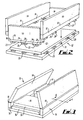
- Fig. 2 is a more schematic exploded view of one of the containers of Fig. 1;
- Fig. 3 is a highly schematic perspective view of the container of Fig. 2 in the partially collapsed condition;
- Fig. 4 is an exploded section along the line IV-IV in Fig. 2;
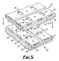
- Fig. 5 shows the containers of Fig. 1 being stacked in the collapsed condition; and
- Fig. 6 is a schematic plan view of the stacking pattern of the containers of Fig. 5.
- Referring to the figures, there is shown in Fig. 1 two
collapsible containers 10 each comprising abase 12, fourside walls 14 which may fold to a stowed or collapsed position (shown in Fig. 5) when the container is not in use. Eachside wall 14 is associated with anintermediate member 16. Hinge means connect (in this example) eachintermediate member 16 with thecorresponding side wall 14. Attachment means (to be described in relation to Fig. 2) attach theintermediate members 16 to thebase 12. Theintermediate members 16 and the base are manufactured separately and subsequently assembled by means of the attachment means to be described. - In more detail, each
container 10 has a generallyrectangular base 12 from which the fourside walls 14 extend upwardly when the container is in the erect condition, to form a generally parallelepipedal container with an open top. In the example shown, which has a base of approximately 600mm x 400mm, one pair of opposed side walls is shorter than the other pair of opposed side walls. - Each side wall is connected along its
lower edge 18 to the correspondingintermediate member 16 which runs along the whole length of thewall 14. The connection is by means of a "live" hinge, that is, a thin web 19 (Fig. 4) of material connecting thewall 14 andmember 16 and sufficiently thin to flex, allowing thewall 14 to hinge relative to themember 16. Preferably, the various components of the container are manufactured in a plastics material, preferably by injection moulding. The side wall and intermediate member can therefore be manufactured as a single element having much reduced thickness at thehinge 19. - When the container is in the erect condition, the
side walls 14 stand on theintermediate members 16. However, thecontainer 10 can be collapsed in the manner indicated in Fig. 3. The twoshorter walls 14 are first folded toward each other to lie across thebase 12. Fig. 3 shows the shorter walls fully folded to this stowed position. It is to be noted that the height of the intermediate members under the shorter walls is less than the height of the intermediate members under the longer walls so that in the position shown in Fig. 3, the upper face of the shorter walls is at or below the line of the hinges connecting the longer walls to their corresponding intermediate members. This allows the longer walls to be folded toward each other, down across the base and over the shorter walls. The container is then in the collapsed position shown in Fig. 5, which also shows additional features to be described below. - The
intermediate members 16 are attached to thebase 12 by a series ofrecesses 20 andprojections 22 shown in Figs. 2 and 4. Eachprojection 22 is generally L-shaped to form a hook having a short downwardly extendinglimb 24 finishing at anelbow 26, from which a generally horizontal and relativelylong limb 28 extends away parallel to the length of themember 16. - The
recesses 20 are generally rectangular and aligned parallel with theintermediate members 16. Their length corresponds with the length of thelimb 28. This allows themembers 16 to be lowered to introduce thelimbs 28 into therecesses 20, whereupon themembers 16 can be slid sideways parallel to the length of themembers 16, to hook thelong limbs 28 under corresponding surfaces 30 (Fig. 4) within therecesses 20. Alternatively, the second movement could be in a different direction, such as twisting. - There are preferably detent means associated with the recesses and projections to hold them together once connected. These may be permanent, but are preferably releasable to allow an
intermediate member 16 to be removed by reversing the sequence of operations described above. This allows anintermediate member 16 and thecorresponding side wall 14 to be removed and replaced, for instance to repair damage. - Arrangements for holding the
intermediate member 16 andbase 12 together may be resilient as indicated in Fig. 2, in which a smallresilient upstand 32 projects above the surface of thebase 12, to be pushed down when theintermediate member 16 is lowered into position. The resilience of theupstand 32 causes it to push theintermediate members 16 upwardly after connection to the base, thereby increasing friction between thelimbs 28 and surfaces 30, to hold theintermediate member 16 in position on thebase 12. - Many other types of connection arrangement could be used to securely connect the
intermediate members 16 to thebase 12. Other types of hinge could also be used. In the example described above, it is preferred to provide the hinge between theintermediate member 16 and theside wall 14, with the attachments between themembers 16 and the base 12 being detachable. However, it may in some circumstances be advantageous to provide the hinge between themember 16 and thebase 12, with themembers 16 and thecorresponding walls 14 being attached by an arrangement similar to that shown, or any of the alternatives. - The containers shown in the drawings also incorporate a number of features which assist stacking. As has been described, the containers have a base 12 and
side walls 14 with an erect condition and a collapsed condition. Thecontainer 10 further comprises stackingformations side walls 14 have top edges (when erect) which are castellated to formnotches 34. These overliedownward projections 36 from the base 12 so that a container base can be stacked on a container below when the lower container is in the erect condition, by lowering the base of the upper container until thebase projections 36 on the upper container sit in thenotches 34 in the lower container. Thenotches 34 andprojections 36 then engage to stop the upper container sliding relative to the lower container. This assists secure stacking. One arrangement usesprojections 36 which fit closely incorresponding notches 34. Alternatively,projections 36 could be shorter than thenotches 34, so that onenotch 34 prevents sliding in one direction, with another notch preventing sliding in the opposite direction. - In the arrangements shown, the locations of the
notches 34 andprojections 36 also allows containers to be stacked when rotated through 90°, there being threenotches 34 andprojections 36 along each longer side of the rectangular container, and twonotches 34 and twoprojections 36 along each shorter side. When stacked in this way, the upper container will overhang the lower container by approximately one third of its length. - Secure stacking in which relative sliding is prevented can also be achieved when the lower container is in the collapsed condition. This is illustrated in Fig. 5. Two containers are shown there, both collapsed.
Depressions 38 formed in the face of theside walls 14 now face upwardly by virtue of the collapsed condition of the containers. In addition,notches 40 around the edges of thewalls 14, including notches along theedge 18, become exposed when the container is collapsed. The arrangement and form of these depressions and notches allows them to receive theprojections 36 from a like container stacked from above. The arrangement allows stacking two containers in alignment, or at right angles to one another (as shown). When stacked at right angles, twoprojections 36 at the short side of the base 12 sit in twonotches 40 at the lower edge of alonger wall 14 of the lower container, leaving athird notch 40 unoccupied. Twoprojections 36 on the base of the upper container sit indepressions 38, one in each of thelonger walls 14 of the lower container. Another two projections 36 (obscured in Fig. 5) sit in notches at the obscured end of thewalls 14. A corresponding twonotches 40 at the visible end are unoccupied. - The spacing and sizes of the
notches 34,projections 36,depressions 38, andnotches 40 locate the upper container on the lower container to stop the stacked containers sliding relative to each other. - The ability to stack collapsed containers at right angles to one another facilitates the creation of a stable stack as will now be described with reference to Fig. 6. First, it should be noted that the
depressions 38 are relatively wide, and allow twoprojections 36 to be located in them, side-by-side, one from each of two containers being stacked side-by-side on the same lower container. - Turning to Fig. 6, a layer in a stack of collapsed containers is formed by five containers arranged as indicated by the solid lines. Three
containers 50 have their long sides adjacent and their short sides aligned. Twomore containers 52 are at right angles to thecontainers 50 with shorter sides abutting and longer sides adjacent the shorter sides of thecontainers 50. Fig. 6 also indicates the arrangement on the layer beneath, using broken lines. It can be seen that the arrangement is the same except that the whole layer has been rotated through a half turn. This results in every container overlying at least two containers on the layer below which, by virtue of the interconnecting notches, projections and depressions, yields a secure stack akin to the building of brickwork. - Containers of 600mm x 400mm base can be stacked in the manner shown on a standard size pallet. Similar overlapping stacking arrangements can be devised for other container sizes, such as 400mm x 300mm, again with similar advantages. The layout of the interlocking formations for the erect and collapsed containers would vary according to the size of container.
- It will be apparent from the above description that many variations and modifications can be made without departing from the scope of the present invention. In particular, many different sizes of container could be designed, with corresponding arrangements of interlocking formations. Other hinge techniques could be used, as could alternative arrangements for attaching the intermediate members to the base. Alternatively, the intermediate member and the base could be hinged, with the wall being made separately. The containers have been described as being of plastics material, but other materials could be used. Lock arrangements could be incorporated to hold the container walls in the erect position.
- Whilst endeavouring in the foregoing specification to draw attention to those features of the invention believed to be of particular importance it should be understood that the Applicant claims protection in respect of any patentable feature or combination of features hereinbefore referred to and/or shown in the drawings whether or not particular emphasis has been placed thereon.
Claims (33)
- A collapsible container comprising a base, at least one side wall which may move to a stowed position when the container is not in use, an intermediate member, hinge means connecting the intermediate member with a first one of the side wall and the base, and attachment means operable to attach the intermediate member to the second one of the side wall and the base, the intermediate member and the said second one of the side wall and the base being manufactured separately, and subsequently assembled by means of the attachment means.
- A container according to claim 1, wherein the intermediate member extends along substantially the whole length of the side wall.
- A container according to claim 1 or 2, wherein the intermediate member is located below the lower edge of the side wall, in use.
- A container according to claim 1, 2 or 3, wherein the attachment means comprise cooperating formations such as cooperating projections and recesses.
- A container according to claim 4, further comprising detent means operable to retain the cooperating formations together.
- A container according to claim 5, wherein the detent means snap together.
- A container according to claim 4, 5 or 6, wherein the cooperating formations are engageable by movement of a first type, and subsequently movable to a locked condition by movement of a second type.
- A container according to claim 7, wherein the first and second types of movement are different.
- A container according to claim 8, wherein the different directions are perpendicular.
- A container according to any of claims 4 to 9, wherein the cooperating formations comprise a hook formation for introduction into a projection in a first direction, movement in a second direction serving to engage the hook with the walls of the recess, thereby locking the projection and recess together.
- A container according to any preceding claim, wherein the attachment means are detachable.
- A container according to any preceding claim, wherein the attachment means incorporate resilience for retaining the attachment means in the attached condition.
- A container according to any preceding claim, wherein the hinge means comprise a live hinge.
- A container according to any preceding claim, wherein the hinge means connects the intermediate member with the side wall, and the attachment means attaches the intermediate member to the base.
- A container according to any preceding claim, wherein the base has rectilinear shape and the container comprises four side walls as aforesaid, and corresponding intermediate members connected and attached as aforesaid.
- A container according to any preceding claim, wherein the walls fold over the base when the container is collapsed.
- A container according to any preceding claim, wherein the container comprises stacking formations able to interlock with corresponding formations on a like container when the containers are in the erect or collapsed condition and are stacked one on the other, the stacked containers being substantially prevented from relative movement by the interlocking of the stacking formations.
- A collapsible container comprising a base, side walls having an erect condition and a collapsed condition, the container further comprising stacking formations able to interlock with corresponding formations on a like container when the containers are in the erect or collapsed condition and are stacked one on the other, the stacked containers being substantially prevented from relative movement by the interlocking of the stacking formations.
- A container according to claim 18, wherein the side walls are connected to the base by hinge means.
- A container according to claim 18 or 19, wherein the side walls lie across the base when in the collapsed condition.
- A container according to claim 18, 19 or 20, wherein the stacking formations comprise projections and recesses.
- A container according to any of claims 18 to 21, wherein the stacking formations are arranged to prevent containers sliding one on the other when stacked.
- A container according to any of claims 18 to 22, wherein the stacking formations comprise castellations along wall edges which are uppermost when the container is in the erect condition.
- A container according to any of claims 18 to 23, wherein the stacking formations comprise castellations located along the lower face of the base.
- A container according to any of claims 18 to 24, wherein the stacking formations comprise recesses or depressions in the face and/or edges of the walls.
- A container according to any of claims 23 to 25, wherein the recesses or depressions are exposed from above when the container is in the collapsed condition, to receive castellations formed on the base of a like container.
- A container according to any of claims 18 to 26, wherein the stacking formations allow containers to be stacked as aforesaid in a plurality of relative orientations.
- A container according to claim 27, wherein the orientations are at right angles to each other.
- A container according to any of claims 18 to 28, wherein the side walls are movable to the collapsed condition when the container is not in use.
- A container according to any of claims 18 to 19, comprising an intermediate member, hinge means connecting the intermediate member with one of the side wall and the base, and attachment means operable to attach the intermediate member to the other of the side wall and the base, the intermediate member and the said other of the side wall and the base being manufactured separately and subsequently assembled by means of the attachment means.
- A container according to any of claims 18 to 30 and any of claims 1 to 17.
- A container substantially as described above, with reference to the accompanying drawings.
- Any novel subject matter or combination including novel subject matter disclosed, whether or not within the scope of or relating to the same invention as any of the preceding claims.
Priority Applications (1)
| Application Number | Priority Date | Filing Date | Title |
|---|---|---|---|
| EP99200692A EP0928745A3 (en) | 1995-07-26 | 1996-07-26 | Stackable collapsible container |
Applications Claiming Priority (5)
| Application Number | Priority Date | Filing Date | Title |
|---|---|---|---|
| GB9515364 | 1995-07-26 | ||
| GB9515364A GB2303616B (en) | 1995-07-26 | 1995-07-26 | Collapsible container |
| US08/703,486 US5797508A (en) | 1995-07-26 | 1996-08-27 | Collapsible container |
| AU64290/96A AU720101B2 (en) | 1996-08-28 | 1996-08-28 | Collapsible container |
| CA002184319A CA2184319A1 (en) | 1995-07-26 | 1996-08-28 | Collapsible container |
Related Child Applications (1)
| Application Number | Title | Priority Date | Filing Date |
|---|---|---|---|
| EP99200692A Division EP0928745A3 (en) | 1995-07-26 | 1996-07-26 | Stackable collapsible container |
Publications (3)
| Publication Number | Publication Date |
|---|---|
| EP0759400A2 true EP0759400A2 (en) | 1997-02-26 |
| EP0759400A3 EP0759400A3 (en) | 1997-05-02 |
| EP0759400B1 EP0759400B1 (en) | 2000-01-19 |
Family
ID=27423655
Family Applications (1)
| Application Number | Title | Priority Date | Filing Date |
|---|---|---|---|
| EP96305602A Expired - Lifetime EP0759400B1 (en) | 1995-07-26 | 1996-07-26 | Collapsible container |
Country Status (4)
| Country | Link |
|---|---|
| US (1) | US5797508A (en) |
| EP (1) | EP0759400B1 (en) |
| CA (1) | CA2184319A1 (en) |
| GB (1) | GB2303616B (en) |
Cited By (10)
| Publication number | Priority date | Publication date | Assignee | Title |
|---|---|---|---|---|
| WO2000029294A3 (en) * | 1998-11-18 | 2001-01-04 | Steiner Tech Gmbh | Container consisting of a plurality of plates |
| WO2005117796A1 (en) * | 2004-06-04 | 2005-12-15 | Gijsbert Michiel Zijlstra | Box |
| WO2005100174A3 (en) * | 2004-04-08 | 2006-01-19 | Meadwestvaco Packaging Systems | Carton and carton blank with reinforced handle structure |
| EP1780133A3 (en) * | 2005-10-31 | 2008-07-09 | thermohauser GmbH | Insulated container |
| EP2241511A1 (en) * | 2009-04-16 | 2010-10-20 | Rehrig Pacific Company | Collapsible Container |
| WO2011141587A1 (en) * | 2010-05-11 | 2011-11-17 | Obeikan Mdf España, S.L. | Stackable container |
| WO2012028567A1 (en) | 2010-09-02 | 2012-03-08 | Febra-Kunststoffe Gmbh | Transporting container |
| EP2845818A1 (en) * | 2013-09-09 | 2015-03-11 | Orbis Corporation | Bulk bin with interlocking elements for stacking |
| FR3028846A1 (en) * | 2014-11-24 | 2016-05-27 | Sofrigam | THERMALLY INSULATING TRANSPORT BODY SYSTEM DELIVERABLE IN A KIT. |
| IT201800009278A1 (en) * | 2018-10-09 | 2020-04-09 | Scs Societa' Costruzione Stampi Srl | PERFECTED FOLDABLE BOX STACKABLE INTERLOCKING. |
Families Citing this family (44)
| Publication number | Priority date | Publication date | Assignee | Title |
|---|---|---|---|---|
| GB9522232D0 (en) | 1995-10-31 | 1996-01-03 | Woodall Plastic Products Ltd | Collapsible crate |
| US6286701B1 (en) * | 1998-02-06 | 2001-09-11 | Schoeller Plast Sa | Container, in particular for transporting fruits and vegetables |
| US6047841A (en) * | 1998-12-22 | 2000-04-11 | Chen; Kun Chen | Assembly type toolbox frame |
| US6398054B1 (en) * | 1999-12-27 | 2002-06-04 | Rehrig Pacific Co. | Collapsible container |
| US20020108950A1 (en) * | 2001-02-14 | 2002-08-15 | Moorman Stephen E. | Collapsible container |
| US7059489B2 (en) * | 2002-10-11 | 2006-06-13 | Rehrig Pacific Company | Portable storage device |
| US7017766B2 (en) * | 2003-03-10 | 2006-03-28 | Rehrig Pacific Company | Collapsible container with side wall latching capability |
| US7100786B2 (en) * | 2003-03-21 | 2006-09-05 | Rehrig Pacific Company | Collapsible container |
| JP3883984B2 (en) * | 2003-05-12 | 2007-02-21 | 三甲株式会社 | Folding container combination module |
| US7195127B2 (en) * | 2003-05-13 | 2007-03-27 | Rehrig Pacific Company | Collapsible container |
| US7475526B2 (en) * | 2004-04-19 | 2009-01-13 | Polymer Logistics (Israel) Ltd. | Knock-down crate with walls stored in base and method employing such a crate |
| US20060213150A1 (en) * | 2005-03-24 | 2006-09-28 | Sonon James A | Method for product handling using a configurable display container |
| US8235217B2 (en) * | 2005-05-24 | 2012-08-07 | Stolzman Michael D | Bulk container with cap and pallet base |
| US20070095842A1 (en) * | 2005-11-01 | 2007-05-03 | Apps William P | Container |
| US7357269B2 (en) * | 2005-11-01 | 2008-04-15 | Rehrig Pacific Company | Container |
| US20080116201A1 (en) * | 2006-11-17 | 2008-05-22 | Kyle Baltz | Container |
| ES2301405B1 (en) * | 2006-12-05 | 2009-05-01 | Marco Esteban, D. Jon. | REMOVABLE BOX. |
| US7641066B2 (en) * | 2007-06-11 | 2010-01-05 | Rehrig Pacific Company | Collapsible container |
| US7717283B2 (en) * | 2007-11-06 | 2010-05-18 | Rehrig Pacific Company | Collapsible container |
| US20090159593A1 (en) * | 2007-12-21 | 2009-06-25 | Apps William P | Collapsible container |
| US7909000B1 (en) * | 2007-12-25 | 2011-03-22 | Horse Safe Products, LLC | Universal panel member for forming feeder assemblies |
| US8261923B2 (en) * | 2008-04-22 | 2012-09-11 | Otto Industries North America, Inc. | Collapsible container |
| WO2010056137A1 (en) * | 2008-11-17 | 2010-05-20 | Corcel Ip Limited | A stackable carton with ventilation channels |
| US8413831B2 (en) | 2009-12-16 | 2013-04-09 | Orbis Corporation | Collapsible bin |
| CA2741242C (en) * | 2010-05-27 | 2019-01-15 | Rehrig Pacific Company | Dual height collapsible container |
| DE102010024097B3 (en) * | 2010-06-17 | 2011-07-14 | Georg Utz Holding Ag | Transport container has rectangular base, at whose lower side support feet are arranged and side walls that are foldably designed around hinges |
| US9617035B2 (en) | 2011-08-10 | 2017-04-11 | Brooks Johnson | Multi-position tool box system and method |
| CN103523328A (en) * | 2012-07-02 | 2014-01-22 | 江苏立华塑料制品有限公司 | Turnover basket |
| US8915397B2 (en) | 2012-11-01 | 2014-12-23 | Orbis Corporation | Bulk container with center support between drop door and side wall |
| EP2783995B1 (en) * | 2013-03-28 | 2016-06-29 | K. Hartwall Oy AB | Logistics crate module and method of transporting goods |
| JP6209390B2 (en) * | 2013-08-08 | 2017-10-04 | 岐阜プラスチック工業株式会社 | Folding container |
| US9708097B2 (en) | 2013-11-15 | 2017-07-18 | Orbis Corporation | Bulk bin with integrated shock absorber |
| US9487326B2 (en) | 2013-11-26 | 2016-11-08 | Orbis Corporation | Bulk bin with panel to panel interlock features |
| CN103754455B (en) * | 2014-01-07 | 2015-09-30 | 常熟市发东塑业有限公司 | Foldable circulation basket |
| WO2015195927A1 (en) | 2014-06-20 | 2015-12-23 | Orbis Corporation | Hinge rod trap for a collapsible bin |
| US9596915B1 (en) | 2014-07-11 | 2017-03-21 | ProSports Technologies, LLC | Sports fan cooler attachment for tailgating purposes |
| US9555921B1 (en) * | 2014-07-11 | 2017-01-31 | ProSports Technologies, LLC | Portable cooler |
| IL237267B (en) * | 2015-02-16 | 2019-08-29 | Dolav Plastic Products Cooperative Soc Ltd | Heavy-duty foldable storage bin |
| US10427837B2 (en) | 2015-04-20 | 2019-10-01 | Orbis Corporation | Container with feature to block fork tine openings |
| CA2960500A1 (en) | 2016-03-11 | 2017-09-11 | Rehrig Pacific Company | Collapsible crate with wood appearance |
| US12448172B2 (en) | 2018-03-05 | 2025-10-21 | Rehrig Pacific Company | Collapsible container |
| US11597557B2 (en) | 2018-10-04 | 2023-03-07 | Rehrig Pacific Company | Reconfigurable beverage crate |
| CN111776422A (en) * | 2020-08-11 | 2020-10-16 | 张国枫 | A portable storage box that can be opened on multiple sides |
| CA3172382A1 (en) | 2021-09-16 | 2023-03-16 | Rehrig Pacific Company | Hybrid collapsible crate |
Family Cites Families (15)
| Publication number | Priority date | Publication date | Assignee | Title |
|---|---|---|---|---|
| GB233946A (en) * | 1924-08-18 | 1925-05-21 | Charles Ernest Barrie | Improvements in shipping case |
| DE2145550C3 (en) * | 1971-09-11 | 1974-07-18 | Walther Dipl.-Ing. 8110 Murnau Zarges | Collapsible container |
| US4044910A (en) * | 1976-05-05 | 1977-08-30 | Box Theodor | Collapsible crate |
| US4098409A (en) * | 1977-03-04 | 1978-07-04 | Moore Iron Works | Foldable shipping rack |
| AU570224B2 (en) * | 1982-11-23 | 1988-03-10 | Technosearch Pty. Limited | Pallet cage |
| US4591065A (en) * | 1984-09-25 | 1986-05-27 | Foy Dennis M | Foldable container assembly |
| IL75934A (en) * | 1985-07-29 | 1990-01-18 | Mercaz Haargazim Ltd | Collapsible plastic container |
| US4662532A (en) * | 1985-11-04 | 1987-05-05 | Steel King Industries, Inc. | Foldable container |
| US4809851A (en) * | 1987-04-03 | 1989-03-07 | World Container Corporation | Collapsible container |
| US5161709A (en) * | 1989-01-30 | 1992-11-10 | World Container Corporation | Hinged collapsible container |
| US5070577A (en) * | 1990-02-09 | 1991-12-10 | World Container Corporation | Seperable hinge |
| DE4137095A1 (en) * | 1991-11-12 | 1993-05-13 | Christian Graalfs | Storage transport container for pot plants - has sidewalls unfolding flat outwards on joints made of protruding webs on walls engaging in slit openings in base plate |
| DE4201145C2 (en) * | 1992-01-17 | 2001-02-08 | Giso Verwaltungsgmbh & Co Beha | Containers made of plastic, in particular vegetable containers, with foldable side walls |
| DE4242679A1 (en) * | 1992-12-17 | 1994-06-23 | Otto Geb Kg | Collapsible transport container as reusable packaging |
| WO1995018047A1 (en) * | 1993-12-30 | 1995-07-06 | Hae Soon Oh | Folding and unfolding box |
-
1995
- 1995-07-26 GB GB9515364A patent/GB2303616B/en not_active Expired - Fee Related
-
1996
- 1996-07-26 EP EP96305602A patent/EP0759400B1/en not_active Expired - Lifetime
- 1996-08-27 US US08/703,486 patent/US5797508A/en not_active Expired - Fee Related
- 1996-08-28 CA CA002184319A patent/CA2184319A1/en not_active Abandoned
Cited By (18)
| Publication number | Priority date | Publication date | Assignee | Title |
|---|---|---|---|---|
| WO2000029294A3 (en) * | 1998-11-18 | 2001-01-04 | Steiner Tech Gmbh | Container consisting of a plurality of plates |
| US6708836B2 (en) | 1998-11-18 | 2004-03-23 | Steiner Technology Gmbh | Container consisting of a plurality of plates |
| WO2005100174A3 (en) * | 2004-04-08 | 2006-01-19 | Meadwestvaco Packaging Systems | Carton and carton blank with reinforced handle structure |
| WO2005117796A1 (en) * | 2004-06-04 | 2005-12-15 | Gijsbert Michiel Zijlstra | Box |
| US7761963B2 (en) | 2004-06-04 | 2010-07-27 | Arne Koch | Box |
| EP1780133A3 (en) * | 2005-10-31 | 2008-07-09 | thermohauser GmbH | Insulated container |
| EP2241511A1 (en) * | 2009-04-16 | 2010-10-20 | Rehrig Pacific Company | Collapsible Container |
| US8056723B2 (en) | 2009-04-16 | 2011-11-15 | Rehrig Pacific Company | Collapsible container |
| WO2011141587A1 (en) * | 2010-05-11 | 2011-11-17 | Obeikan Mdf España, S.L. | Stackable container |
| US9434507B2 (en) | 2010-05-11 | 2016-09-06 | Obeikan Mdf Espana, S.L. | Stackable container |
| WO2012028567A1 (en) | 2010-09-02 | 2012-03-08 | Febra-Kunststoffe Gmbh | Transporting container |
| EP2845818A1 (en) * | 2013-09-09 | 2015-03-11 | Orbis Corporation | Bulk bin with interlocking elements for stacking |
| FR3028846A1 (en) * | 2014-11-24 | 2016-05-27 | Sofrigam | THERMALLY INSULATING TRANSPORT BODY SYSTEM DELIVERABLE IN A KIT. |
| FR3028845A1 (en) * | 2014-11-24 | 2016-05-27 | Sofrigam | THERMALLY INSULATING TRANSPORT BODY SYSTEM DELIVERABLE IN A KIT. |
| WO2016083710A1 (en) * | 2014-11-24 | 2016-06-02 | Sofrigam | Thermally insulating transport case system that is deliverable in kit form |
| IT201800009278A1 (en) * | 2018-10-09 | 2020-04-09 | Scs Societa' Costruzione Stampi Srl | PERFECTED FOLDABLE BOX STACKABLE INTERLOCKING. |
| EP3636557A1 (en) | 2018-10-09 | 2020-04-15 | S.C.S. Socita' Costruzione Stampi S.r.l. | Improved stackable interlocking collapsible crate |
| WO2020074408A1 (en) | 2018-10-09 | 2020-04-16 | S.C.S. Societa' Costruzione Stampi S.R.L. | Improved stackable interlocking collapsible crate |
Also Published As
| Publication number | Publication date |
|---|---|
| GB2303616B (en) | 1999-09-15 |
| US5797508A (en) | 1998-08-25 |
| EP0759400B1 (en) | 2000-01-19 |
| CA2184319A1 (en) | 1998-03-01 |
| GB2303616A (en) | 1997-02-26 |
| EP0759400A3 (en) | 1997-05-02 |
| GB9515364D0 (en) | 1995-09-20 |
Similar Documents
| Publication | Publication Date | Title |
|---|---|---|
| US5797508A (en) | Collapsible container | |
| US6722515B2 (en) | Folding crate | |
| US6059114A (en) | Container | |
| EP0125307B1 (en) | Container | |
| US5617953A (en) | Stackable/nestable containers | |
| US5092385A (en) | Interlocking panel system | |
| US5289935A (en) | Container with sidewall extension and method for making | |
| US20250214746A1 (en) | Palletized Container with Clip-Locked Sleeve | |
| EP0928745A2 (en) | Stackable collapsible container | |
| US11167920B2 (en) | Stand system for arranging panels | |
| US20110174655A1 (en) | Container | |
| MXPA06009837A (en) | Interlocking roll support and spacing structure. | |
| JP2002002696A (en) | Loading structure of folding container | |
| WO2000059789A1 (en) | Panel assembly | |
| US5275289A (en) | Frame container support and stackable container system using same | |
| GB2069464A (en) | Corner members for stckable boxes | |
| AU720101B2 (en) | Collapsible container | |
| EP1261529B1 (en) | Stackable plastic container with collapsible walls, in particular for fruit and vegetable products | |
| US5762261A (en) | Collapsible container | |
| AU2011265443A1 (en) | Collapsible document tray | |
| CN211495224U (en) | Rack system for arranging panels | |
| JPH0411931Y2 (en) | ||
| JPH08506788A (en) | Returnable packaging system | |
| EP0875464A1 (en) | Container and lid | |
| WO2000012396A1 (en) | Transport package |
Legal Events
| Date | Code | Title | Description |
|---|---|---|---|
| PUAI | Public reference made under article 153(3) epc to a published international application that has entered the european phase |
Free format text: ORIGINAL CODE: 0009012 |
|
| AK | Designated contracting states |
Kind code of ref document: A2 Designated state(s): BE DE ES FR IE IT LU NL PT SE |
|
| AX | Request for extension of the european patent |
Free format text: AL;LT;LV;SI |
|
| PUAL | Search report despatched |
Free format text: ORIGINAL CODE: 0009013 |
|
| AK | Designated contracting states |
Kind code of ref document: A3 Designated state(s): AT BE CH DE DK ES FI FR GB GR IE IT LI LU MC NL PT SE |
|
| AX | Request for extension of the european patent |
Free format text: AL;LT;LV;SI |
|
| RBV | Designated contracting states (corrected) |
Designated state(s): BE DE ES FR GB IE IT LU NL PT SE |
|
| 17P | Request for examination filed |
Effective date: 19970709 |
|
| 17Q | First examination report despatched |
Effective date: 19980226 |
|
| GRAG | Despatch of communication of intention to grant |
Free format text: ORIGINAL CODE: EPIDOS AGRA |
|
| GRAG | Despatch of communication of intention to grant |
Free format text: ORIGINAL CODE: EPIDOS AGRA |
|
| GRAH | Despatch of communication of intention to grant a patent |
Free format text: ORIGINAL CODE: EPIDOS IGRA |
|
| DAX | Request for extension of the european patent (deleted) | ||
| GRAH | Despatch of communication of intention to grant a patent |
Free format text: ORIGINAL CODE: EPIDOS IGRA |
|
| RBV | Designated contracting states (corrected) |
Designated state(s): BE DE ES FR IE IT LU NL PT SE |
|
| GRAA | (expected) grant |
Free format text: ORIGINAL CODE: 0009210 |
|
| AK | Designated contracting states |
Kind code of ref document: B1 Designated state(s): BE DE ES FR IE IT LU NL PT SE |
|
| PG25 | Lapsed in a contracting state [announced via postgrant information from national office to epo] |
Ref country code: SE Free format text: THE PATENT HAS BEEN ANNULLED BY A DECISION OF A NATIONAL AUTHORITY Effective date: 20000119 Ref country code: NL Free format text: LAPSE BECAUSE OF FAILURE TO SUBMIT A TRANSLATION OF THE DESCRIPTION OR TO PAY THE FEE WITHIN THE PRESCRIBED TIME-LIMIT Effective date: 20000119 Ref country code: IT Free format text: LAPSE BECAUSE OF FAILURE TO SUBMIT A TRANSLATION OF THE DESCRIPTION OR TO PAY THE FEE WITHIN THE PRESCRIBED TIME-LIMIT;WARNING: LAPSES OF ITALIAN PATENTS WITH EFFECTIVE DATE BEFORE 2007 MAY HAVE OCCURRED AT ANY TIME BEFORE 2007. THE CORRECT EFFECTIVE DATE MAY BE DIFFERENT FROM THE ONE RECORDED. Effective date: 20000119 Ref country code: FR Free format text: LAPSE BECAUSE OF FAILURE TO SUBMIT A TRANSLATION OF THE DESCRIPTION OR TO PAY THE FEE WITHIN THE PRESCRIBED TIME-LIMIT Effective date: 20000119 Ref country code: ES Free format text: THE PATENT HAS BEEN ANNULLED BY A DECISION OF A NATIONAL AUTHORITY Effective date: 20000119 Ref country code: BE Free format text: LAPSE BECAUSE OF FAILURE TO SUBMIT A TRANSLATION OF THE DESCRIPTION OR TO PAY THE FEE WITHIN THE PRESCRIBED TIME-LIMIT Effective date: 20000119 |
|
| REF | Corresponds to: |
Ref document number: 69606240 Country of ref document: DE Date of ref document: 20000224 |
|
| REG | Reference to a national code |
Ref country code: IE Ref legal event code: FG4D |
|
| PG25 | Lapsed in a contracting state [announced via postgrant information from national office to epo] |
Ref country code: PT Free format text: LAPSE BECAUSE OF FAILURE TO SUBMIT A TRANSLATION OF THE DESCRIPTION OR TO PAY THE FEE WITHIN THE PRESCRIBED TIME-LIMIT Effective date: 20000419 |
|
| PG25 | Lapsed in a contracting state [announced via postgrant information from national office to epo] |
Ref country code: DE Free format text: LAPSE BECAUSE OF FAILURE TO SUBMIT A TRANSLATION OF THE DESCRIPTION OR TO PAY THE FEE WITHIN THE PRESCRIBED TIME-LIMIT Effective date: 20000420 |
|
| RAP2 | Party data changed (patent owner data changed or rights of a patent transferred) |
Owner name: MCKECHNIE COMPONENTS LIMITED |
|
| EN | Fr: translation not filed | ||
| NLV1 | Nl: lapsed or annulled due to failure to fulfill the requirements of art. 29p and 29m of the patents act | ||
| PG25 | Lapsed in a contracting state [announced via postgrant information from national office to epo] |
Ref country code: LU Free format text: LAPSE BECAUSE OF NON-PAYMENT OF DUE FEES Effective date: 20000726 Ref country code: IE Free format text: LAPSE BECAUSE OF NON-PAYMENT OF DUE FEES Effective date: 20000726 |
|
| PLBE | No opposition filed within time limit |
Free format text: ORIGINAL CODE: 0009261 |
|
| STAA | Information on the status of an ep patent application or granted ep patent |
Free format text: STATUS: NO OPPOSITION FILED WITHIN TIME LIMIT |
|
| 26N | No opposition filed | ||
| REG | Reference to a national code |
Ref country code: IE Ref legal event code: MM4A |