EP0759059B1 - Electroflocculator for solids removal in hydrocarbon processes - Google Patents
Electroflocculator for solids removal in hydrocarbon processes Download PDFInfo
- Publication number
- EP0759059B1 EP0759059B1 EP95920393A EP95920393A EP0759059B1 EP 0759059 B1 EP0759059 B1 EP 0759059B1 EP 95920393 A EP95920393 A EP 95920393A EP 95920393 A EP95920393 A EP 95920393A EP 0759059 B1 EP0759059 B1 EP 0759059B1
- Authority
- EP
- European Patent Office
- Prior art keywords
- catalyst particles
- solid catalyst
- electric field
- process fluid
- particles
- Prior art date
- Legal status (The legal status is an assumption and is not a legal conclusion. Google has not performed a legal analysis and makes no representation as to the accuracy of the status listed.)
- Expired - Lifetime
Links
- 238000000034 method Methods 0.000 title claims description 87
- 230000008569 process Effects 0.000 title claims description 67
- 239000004215 Carbon black (E152) Substances 0.000 title claims description 20
- 229930195733 hydrocarbon Natural products 0.000 title claims description 20
- 150000002430 hydrocarbons Chemical class 0.000 title claims description 20
- 239000007787 solid Substances 0.000 title description 10
- 239000002245 particle Substances 0.000 claims description 87
- 239000012530 fluid Substances 0.000 claims description 53
- 239000003054 catalyst Substances 0.000 claims description 41
- 239000011949 solid catalyst Substances 0.000 claims description 37
- 230000005684 electric field Effects 0.000 claims description 29
- 239000002002 slurry Substances 0.000 claims description 20
- 229910052751 metal Inorganic materials 0.000 claims description 18
- 239000002184 metal Substances 0.000 claims description 18
- 238000006243 chemical reaction Methods 0.000 claims description 12
- 239000000203 mixture Substances 0.000 claims description 8
- 230000005484 gravity Effects 0.000 claims description 3
- 239000007788 liquid Substances 0.000 description 22
- 230000000694 effects Effects 0.000 description 8
- 238000012360 testing method Methods 0.000 description 6
- XEEYBQQBJWHFJM-UHFFFAOYSA-N Iron Chemical compound [Fe] XEEYBQQBJWHFJM-UHFFFAOYSA-N 0.000 description 5
- GWEVSGVZZGPLCZ-UHFFFAOYSA-N Titan oxide Chemical compound O=[Ti]=O GWEVSGVZZGPLCZ-UHFFFAOYSA-N 0.000 description 4
- 239000011521 glass Substances 0.000 description 4
- 230000003134 recirculating effect Effects 0.000 description 4
- 230000015572 biosynthetic process Effects 0.000 description 3
- 229910017052 cobalt Inorganic materials 0.000 description 3
- 239000010941 cobalt Substances 0.000 description 3
- GUTLYIVDDKVIGB-UHFFFAOYSA-N cobalt atom Chemical compound [Co] GUTLYIVDDKVIGB-UHFFFAOYSA-N 0.000 description 3
- 238000002474 experimental method Methods 0.000 description 3
- 238000003786 synthesis reaction Methods 0.000 description 3
- 238000005189 flocculation Methods 0.000 description 2
- 239000012634 fragment Substances 0.000 description 2
- 229910052742 iron Inorganic materials 0.000 description 2
- 230000005012 migration Effects 0.000 description 2
- 238000013508 migration Methods 0.000 description 2
- BASFCYQUMIYNBI-UHFFFAOYSA-N platinum Chemical compound [Pt] BASFCYQUMIYNBI-UHFFFAOYSA-N 0.000 description 2
- 238000005054 agglomeration Methods 0.000 description 1
- 230000002776 aggregation Effects 0.000 description 1
- 229910052782 aluminium Inorganic materials 0.000 description 1
- XAGFODPZIPBFFR-UHFFFAOYSA-N aluminium Chemical compound [Al] XAGFODPZIPBFFR-UHFFFAOYSA-N 0.000 description 1
- PNEYBMLMFCGWSK-UHFFFAOYSA-N aluminium oxide Inorganic materials [O-2].[O-2].[O-2].[Al+3].[Al+3] PNEYBMLMFCGWSK-UHFFFAOYSA-N 0.000 description 1
- 230000008859 change Effects 0.000 description 1
- 238000003889 chemical engineering Methods 0.000 description 1
- 238000001311 chemical methods and process Methods 0.000 description 1
- 238000004140 cleaning Methods 0.000 description 1
- ZEWGRSAJWPFTRK-UHFFFAOYSA-N cobalt rhenium Chemical compound [Co].[Re] ZEWGRSAJWPFTRK-UHFFFAOYSA-N 0.000 description 1
- 238000012790 confirmation Methods 0.000 description 1
- 238000011437 continuous method Methods 0.000 description 1
- 238000013073 enabling process Methods 0.000 description 1
- 238000001914 filtration Methods 0.000 description 1
- 239000010419 fine particle Substances 0.000 description 1
- 230000016615 flocculation Effects 0.000 description 1
- 239000011888 foil Substances 0.000 description 1
- 230000003993 interaction Effects 0.000 description 1
- 150000002500 ions Chemical class 0.000 description 1
- 238000009533 lab test Methods 0.000 description 1
- 239000013618 particulate matter Substances 0.000 description 1
- 229910052697 platinum Inorganic materials 0.000 description 1
- 239000011148 porous material Substances 0.000 description 1
- 238000005086 pumping Methods 0.000 description 1
- 230000009467 reduction Effects 0.000 description 1
- 229910052702 rhenium Inorganic materials 0.000 description 1
- WUAPFZMCVAUBPE-UHFFFAOYSA-N rhenium atom Chemical compound [Re] WUAPFZMCVAUBPE-UHFFFAOYSA-N 0.000 description 1
- 230000000630 rising effect Effects 0.000 description 1
- 238000004062 sedimentation Methods 0.000 description 1
- 238000000926 separation method Methods 0.000 description 1
- 239000008247 solid mixture Substances 0.000 description 1
- 239000000126 substance Substances 0.000 description 1
- 230000000007 visual effect Effects 0.000 description 1
Images
Classifications
-
- C—CHEMISTRY; METALLURGY
- C10—PETROLEUM, GAS OR COKE INDUSTRIES; TECHNICAL GASES CONTAINING CARBON MONOXIDE; FUELS; LUBRICANTS; PEAT
- C10G—CRACKING HYDROCARBON OILS; PRODUCTION OF LIQUID HYDROCARBON MIXTURES, e.g. BY DESTRUCTIVE HYDROGENATION, OLIGOMERISATION, POLYMERISATION; RECOVERY OF HYDROCARBON OILS FROM OIL-SHALE, OIL-SAND, OR GASES; REFINING MIXTURES MAINLY CONSISTING OF HYDROCARBONS; REFORMING OF NAPHTHA; MINERAL WAXES
- C10G32/00—Refining of hydrocarbon oils by electric or magnetic means, by irradiation, or by using microorganisms
- C10G32/02—Refining of hydrocarbon oils by electric or magnetic means, by irradiation, or by using microorganisms by electric or magnetic means
Definitions
- the present invention is directed to a continuous method of removing solid catalyst particles from hydrocarbon process fluids, including Fischer-Tropsch process fluids, using an electric field preferably an electric field generated by an electroflocculating apparatus.
- the invention is further directed to such apparatus.
- WO 85/03017 a method and apparatus are described for removing particulate matter (for example catalyst fines) suspended in low dielectric, low conductivity liquids (for example oil). A unipolar current of extrinsic ions is passed through the flowing liquid to charge the particles. The charged particles are then removed by agglomeration or sedimentation.
- particulate matter for example catalyst fines
- low dielectric, low conductivity liquids for example oil
- a method for separating solid catalyst particles from hydrocarbon process fluids comprises the steps of:
- the process further comprises the step of:
- the process further comprises the step of:
- the present invention advantageously allows substantially catalyst particle-free fluid to be removed from a process without the use of filters which become blinded (clogged) necessitating interrupting the process for filter replacement or cleaning.
- the method of the invention has no effect on the catalyst surface area, particle density, particle size, or catalyst activity.
- the apparatus provides for the continuous removal of solid catalyst particles from process fluids and conveyance of the removed solid catalyst particles, which deagglomerate once removed from the electric field back into the reaction zone, if desired.
- the electroflocculator can be located within or without (outside) the reactor.
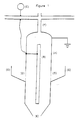
- Figure 1 schematically depicts one example of an electroflocculating apparatus where the electroflocculator is located inside a hydrocarbon synthesis bubble column.
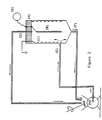
- FIG. 2 schematically shows another example of an electroflocculator apparatus.
- the instant invention teaches a method for separating catalyst particles from process fluids having such particles suspended therein.
- the method is capable of separating particles which are 1 micron in size up to and including a 0.3 cm particles.
- the invention can remove suspended particles from any type of hydrocarbon liquid.
- the invention is particularly useful for removing catalyst particles from slurry process fluids, particularly bubble column slurry process fluids, ebulating bed processes and stirred process fluids.
- catalyst particles can be separated from the process fluids in accordance with the instant invention without any pretreatment of the process fluids. Thus, they can be introduced directly into the electroflocculator apparatusus from the hydrocarbon reaction vessel.
- the invention merely requires that the solid catalyst particles contain at least 0.1 wt.%, based on the total particle weight, of a metal in its zero valence state.
- Applicants have discovered that applying an electric field to a process fluid which contains about 0.1 to 50 wt.%, preferably 0.3 to 50 wt.% suspended solid catalyst particles containing at least 0.1 wt.% metal in the zero valence state, causes the solid catalyst particles to be temporarily agglomerated, causing them to settle, through gravity, out of the process fluid enabling the ready removal of process fluid from the fluid/solid mixture.
- the catalyst particles Once the catalyst particles have settled and passed out of the electric field, they deagglomerate to their original size and are usable once again. Hence, they can be immediately returned to the reaction zone without interruption of the process being performed and a recirculating process (which reutilizes the deagglomerated catalyst particles) can be conducted.
- the present invention can be utilized to reclaim, e.g., supported Fischer-Tropsch catalysts from slurry Fischer-Tropsch media.
- the invention can additionally be used on promoted cobalt catalyst such as rhenium promoted cobalt.
- the invention can be used to separate a cobalt-rhenium on titania catalyst from Fischer-Tropsch media.
- the above catalysts are merely illustrative and are not meant to be limiting.
- the instant invention is capable of removing >95% of the solid catalyst particles directly from the process fluid without the aid of any pretreatment steps.
- a slurry process fluid can be passed through an electroflocculator, in accordance with the instant invention, whereupon the catalyst particles present will agglomerate and settle to the electroflocculator vessel bottom. Once the catalyst particles are outside of the forces of the electrical field, they deagglomerate. The catalyst particles can then be passed back into the slurry process reaction zone if desired. Process fluid having catalyst particles removed therefrom can be withdrawn from the electroflocculator vessel by any suitable means. In the instant process there is substantially no migration of the catalyst to the electrodes, preferably no such migration will occur.
- the preferred mode of carrying out the instant invention is to pass the process fluid having suspended solid catalyst particle therein through an electroflocculator by utilizing techniques such as the "downcomer" effect commonly practiced in chemical engineering.
- the term "downcomer effect” used herein refers to a well-known technique for causing liquid in a first upwardly or downwardly extending volume (e.g., in a tube or vessel) to have a higher apparent density than liquid in a second upwardly or downwardly extending volume (e.g., in another tube or vessel) wherein liquid can flow between the upper regions of both volumes and between the lower regions of both volumes.
- the apparent liquid density in the second volume is reduced by bubbles of gas therein.
- the differing liquid densities in the two connected volumes cause upward liquid flow in the second volume and downward liquid flow in the first volume.
- the flocculator is a vessel equipped with an AC voltage source across two electrodes (one electrode being "hot” (i.e. connected to a source of alternating current), and the other earthed or ground) capable of producing AC voltage of from about 0.1 hertz, up to and including about 5000 hertz of current.
- the electrical field strength produced will be from about 100 volts/cm up to and including about 100,000 volts/cm, preferably from about 200 to about 50,000 volts/cm.
- the electroflocculator will be equipped with a metal screen, at the area where the process fluid and catalyst particles enter to exclude gas bubbles.
- the openings of the screen should be adequate to exclude most gas bubbles in the process fluid but allow the passing of the particles.
- the electroflocculator will be equipped with both a baffle and a metal screen. The baffle helps to further exclude gas bubbles. Once the solid catalyst particles experience the electric field, they agglomerate and settle through the opening at the bottom of the electroflocculator. They can thus be readily removed.
- the departiculated process stream can be collected by any suitable means such as siphoning from near the top of the electroflocculator, decanting, etc.
- the instant method can be carried out with an electroflocculator inside the reaction vessel, enabling the agglomerated catalyst particles, which deagglomerate without any change in size, surface area, particle density or catalyst activity, to be passed back into the reaction zone once removed from the electroflocculator.
- the electroflocculator could alternatively be external to the reaction vessel itself. In the external setup, the deagglomerated particles may be returned to the reaction zone by any suitable means such as pumping.
- the small catalyst particles having zero valence metal therein, will experience electric dipole/dipole interactions and will flocculate to agglomerates that exhibit a much higher settling velocity than deagglomerated particles. Because gas will have preferably been removed from the fluid, there will be a driving force for the liquid to flow downward due to the Downcomer effect. This Downcomer effect will be countered by any process fluid removal during settling. Provided the net rising velocity of the process liquid is less than the settling velocity of the agglomerated particles, most particles can be removed through enhanced settling of the agglomerates.
- the electroflocculator may be equipped with a screen or filter at the product withdrawal outlet to filter any solid residual catalyst particles that might be present near the siphoning outlet due to inadequate residence times.
- the horizontal cross-sectional area of the upper zone of the electroflocculator, the zone of high electric field above the entrance and below the exit port for clarified product, will be sized such that the liquid upflow velocity in this zone is about a factor of 2 to about 40 of the Stokes velocity of the particles being separated.
- the height of this zone should be such that it allows a residence time of at least 0.1 minutes, preferably at least about 0.5 minutes. The longer the residence time, the greater the departiculation efficiency.
- the apparatus which will preferably be used to carry out the method of the instant invention will consist of a reactor vessel equipped with an electroflocculator attached to the outside of the reactor or present within the reactor. Additionally, the electrodes of the electroflocculator may be within or external to the flocculator shell. The electrodes need only produce an electric field which penetrates the process fluid having suspended catalyst particles therein, they needn't directly contact the fluid.
- the electroflocculator on the outside of the reactor vessel will be piped to the reactor and will contain a valve for process fluid drawoff.
- the bottom of the flocculator will be piped back into the reactor to enable the agglomerated catalyst particles to be removed from the electric field, deagglomerated and passed back into the reactor to participate in the reaction being carried out if a recirculating process is desired.
- the electroflocculator When the electroflocculator is contained within the reactor, its vessel walls will preferably have a portion composed of wire mesh of about 200-2000 micron opening size, which will allow the slurry process fluid to flow into the electroflocculator.
- the bottom of the flocculator will be open, allowing agglomerated particles to pass out of the flocculator and into the process vessel.
- a portion of the flocculator, preferably the top, will protrude from the reactor vessel, enabling process fluid having catalyst removed therefrom to be siphoned off.
- the process fluid withdrawal port will be inside the process vessel allowing liquid to be returned to the reaction zone.
- the electroflocculator is located inside a hydrocarbon synthesis bubble column reactor. It consists of a hollow metal shell (A) which serves as a ground electrode, a center electrode (b) connected to a high voltage source (C) which electrode is insulated from the shell (A). Slurry process fluid enters through ports (D) which are metal screens and serve also as grounded grid electrodes. The bottom of the shell is open (E) to the reactor to allow for deagglomerated particles to be expelled from the shell. The top of the shell is connected to a tube (F) which serves as a drawoff port for the removal of product fluid.
- the efficiency of the cylinder has been increased by the addition of a baffle plate (G) external to the shell beneath the screen.
- the baffle prevents gas bubbles from contacting the screen. Removal of gas bubbles sets up a gradient which promotes the continuous flow of slurry from the reactor into the shell and exit through the opening (E) due to the Downcomer effect.
- the system comprises a shell (A) equipped with an electrode pair consisting of a metal rod (B) connected to a high voltage source (D) and a metal mesh screen (C) connected to the ground.
- a recirculating pump (H) is used to pump feed to the electroflocculator through port (E). Concentrated slurry exits the flocculator via exit port (F) and is then recirculated via the pump. Departiculated raffinate is withdrawn via port (G).
- the process fluids which are clarified by use of the instant invention have a dielectric constant of about 2 to about 4, preferably about 2 to about 3. They exhibit an electric conductivity less than about 1 x 10 -10 ohm -1 m -1 , preferably less than 5 x 10 -11 ohm -1 m -1 .
- the experiments were carried out in a 4 ⁇ 76 cm ID by 13 ⁇ 97 cm long (1 7/8" ID by 5.5" long) glass vessel fitted with an electrode pair consisting of a 4 ⁇ 32 cm D x 7 ⁇ 62 cm L (1.7"D x 3"L) cylindrical metal screen and a central electrode.
- the electrodes were connected to the terminals of a high voltage power source capable of generating up to 10 thousand volts of electric potential at frequencies ranging from 40 hertz to 250 hertz.
- a second series of experiments were carried out in an apparatus shown in Figure 2 which was designed to simulate the operation of which was designed to simulate the operation of an electroflocculator to confine catalyst in a chemical reactor.
- a 4 ⁇ 76 cm ID by 13 ⁇ 97 cm high (1 7/8" ID by 5.5" high) glass vessel was fitted with an electrode pair consisting of a 4 ⁇ 32 cm D x 7 ⁇ 62 cm L (1.7"D x 3"L) cylindrical metal screen and a central electrode. They were connected to the terminals of a high voltage power source capable of generating up to 10 thousand volts, producing an electric field of 2000 to 4000 volts/cm at frequencies from 50 to 250 hertz.
- Slurry was fed from a pump into the side of the electroflocculator vessel close to the bottom of the electrode pair at a flow rate of about 1300 cc/min.
- the solid particles were to be electroflocculated in the zone between the two electrodes, settled to the bottom of the vessel, and removed as a concentrated slurry at flow rates from 840 to 1080 cc/min.
- the raffinate with solids removed exited from the top of the vessel at flow rates from 280 to 420 cc/min.
- the returned concentrated slurry and raffinate streams were remixed to reconstitute the feed for a continuous test to reach steady state.
- a small batch electroflocculation test tube was set up to allow a visual confirmation of the flocculation when the electric voltage was applied to the slurry.
- two aluminum foil electrodes were attached to the outside of the glass tube, and connected to the 10 KV/200 hertz voltage source.
Landscapes
- Chemical & Material Sciences (AREA)
- Oil, Petroleum & Natural Gas (AREA)
- Life Sciences & Earth Sciences (AREA)
- Microbiology (AREA)
- Engineering & Computer Science (AREA)
- Chemical Kinetics & Catalysis (AREA)
- General Chemical & Material Sciences (AREA)
- Organic Chemistry (AREA)
- Production Of Liquid Hydrocarbon Mixture For Refining Petroleum (AREA)
- Catalysts (AREA)
- Organic Low-Molecular-Weight Compounds And Preparation Thereof (AREA)
Description


Claims (10)
- A method for separating solid catalyst particles from hydrocarbon process fluids, comprising the steps of:(a) subjecting a mixture of a process fluid and solid catalyst particles to an electric field, said solid catalyst particles containing at least 0.1 wt.% metal in the zero valence state, wherein said process fluid exhibits an electric conductivity less than 1 x 10⁻¹⁰ ohm-1 m-1, and said electric field has an electric field strength of greater than 100 volts/cm and a frequency of at least 0.1 hertz, to produce agglomerated solid catalyst particles;(b) separating, by gravity, said agglomerated solid catalyst particles from said hydrocarbon process fluid.
- A method according to claim 1 comprising step (c), removing said separated agglomerated solid catalyst particles from said electric field to produce deagglomerated solid catalyst particles.
- A method according to claim 2 comprising step (d), reintroducing said deagglomerated solid catalyst particles into a hydrocarbon process reaction zone.
- A method according to any one of claims 1 to 3 wherein said solid catalyst particles are 1µm to 0.3 cm particles.
- A method according to any one of claims 1 to 4 wherein said mixture of process fluid and solid catalyst particles contains 0.1 to 50 wt.% of solid catalyst particles.
- A method according to any one of claims 1 to 5 wherein said mixture of process fluid and solid catalyst particles is introduced directly into said electric field without any pretreatment.
- A method according to any one of claims 1 to 6 comprising removing >95% of said solid catalyst particles from said mixture of process fluid and solid catalyst particles.
- A method according to any one of claims 1 to 7 wherein said process fluid is a slurry, ebullating bed or stirred process fluid.
- A reactor apparatus for the continuous removal of solid catalyst particles containing at least 0.1 wt.% metal in the zero valence state, from slurry process fluids; wherein a hydrocarbon process vessel is attached to or associated with an electroflocculating apparatus, said electroflocculating apparatus comprising:(a) a hollow shell having at least one inlet for the introduction of a mixture of hydrocarbon process fluids and solid catalyst particles, said catalyst particles containing at least 0.1 wt.% metal in the zero valence state, a top outlet for drawing off product fluid and a bottom outlet for the discharge of deagglomerated catalyst particles;(b) a plurality of electrodes in functional relation with said hollow shell, wherein said electrodes extend above said hollow shell inlet and;(c) a high voltage power source coupled to said electrodes and capable of producing an electric field strength of greater than 100 volts/cm and a frequency of 0.1 to 5000 Hz within said hollow shell.
- An apparatus according to claim 9 wherein said electroflocculator is located within or without the reactor.
Applications Claiming Priority (5)
| Application Number | Priority Date | Filing Date | Title |
|---|---|---|---|
| US24030894A | 1994-05-10 | 1994-05-10 | |
| US240308 | 1994-05-10 | ||
| US41832495A | 1995-04-07 | 1995-04-07 | |
| US418324 | 1995-04-07 | ||
| PCT/US1995/005869 WO1995030726A1 (en) | 1994-05-10 | 1995-05-10 | Electroflocculator for solids removal in hydrocarbon processes |
Publications (2)
| Publication Number | Publication Date |
|---|---|
| EP0759059A1 EP0759059A1 (en) | 1997-02-26 |
| EP0759059B1 true EP0759059B1 (en) | 1999-01-20 |
Family
ID=26933319
Family Applications (1)
| Application Number | Title | Priority Date | Filing Date |
|---|---|---|---|
| EP95920393A Expired - Lifetime EP0759059B1 (en) | 1994-05-10 | 1995-05-10 | Electroflocculator for solids removal in hydrocarbon processes |
Country Status (6)
| Country | Link |
|---|---|
| EP (1) | EP0759059B1 (en) |
| AU (1) | AU694231B2 (en) |
| CA (1) | CA2190026C (en) |
| DE (1) | DE69507468T2 (en) |
| NO (1) | NO964737D0 (en) |
| WO (1) | WO1995030726A1 (en) |
Families Citing this family (5)
| Publication number | Priority date | Publication date | Assignee | Title |
|---|---|---|---|---|
| GB0306307D0 (en) | 2003-03-19 | 2003-04-23 | Bp Exploration Operating | Electromechanical filter |
| GB2404885B (en) * | 2003-08-12 | 2006-03-01 | Mi Llc | Electrical treatment for oil based drilling or completion fluids |
| US8142634B2 (en) | 2007-03-09 | 2012-03-27 | M-I L.L.C. | Method and apparatus for electrophoretic separation of solids and water from oil based mud |
| CN108165298B (en) * | 2018-01-04 | 2020-03-31 | 中石化炼化工程(集团)股份有限公司 | Oil slurry purification method, oil slurry purification device and oil slurry purification equipment |
| CN111303937A (en) * | 2019-08-20 | 2020-06-19 | 武汉兰兆科技有限公司 | Electric separation device and electric separation process for on-line recycling of Fischer-Tropsch synthesis catalyst |
Family Cites Families (4)
| Publication number | Priority date | Publication date | Assignee | Title |
|---|---|---|---|---|
| US3928158A (en) * | 1973-05-22 | 1975-12-23 | Gulf Research Development Co | Electrofilter |
| US4358379A (en) * | 1980-11-21 | 1982-11-09 | Noboru Inoue | Process for refining electric insulating liquids |
| US4579637A (en) * | 1984-01-10 | 1986-04-01 | American Filtrona Corporation | Method and apparatus for separating impurities from low conductivity liquids |
| US5308586A (en) * | 1992-05-01 | 1994-05-03 | General Atomics | Electrostatic separator using a bead bed |
-
1995
- 1995-05-10 EP EP95920393A patent/EP0759059B1/en not_active Expired - Lifetime
- 1995-05-10 AU AU25858/95A patent/AU694231B2/en not_active Ceased
- 1995-05-10 CA CA002190026A patent/CA2190026C/en not_active Expired - Fee Related
- 1995-05-10 DE DE69507468T patent/DE69507468T2/en not_active Expired - Fee Related
- 1995-05-10 WO PCT/US1995/005869 patent/WO1995030726A1/en active IP Right Grant
-
1996
- 1996-11-08 NO NO964737A patent/NO964737D0/en not_active Application Discontinuation
Also Published As
| Publication number | Publication date |
|---|---|
| AU694231B2 (en) | 1998-07-16 |
| EP0759059A1 (en) | 1997-02-26 |
| CA2190026A1 (en) | 1995-11-16 |
| WO1995030726A1 (en) | 1995-11-16 |
| DE69507468D1 (en) | 1999-03-04 |
| DE69507468T2 (en) | 1999-09-02 |
| NO964737L (en) | 1996-11-08 |
| NO964737D0 (en) | 1996-11-08 |
| AU2585895A (en) | 1995-11-29 |
| CA2190026C (en) | 2005-04-12 |
Similar Documents
| Publication | Publication Date | Title |
|---|---|---|
| JP3641008B2 (en) | Method and apparatus for treating an untreated liquid stream | |
| US9011696B2 (en) | Magnetic separation combined with dynamic settling for fischer-tropsch processes | |
| AU2003235080B2 (en) | Solid-liquid separation system | |
| WO2002097007A2 (en) | Dynamic settler | |
| EP0759059B1 (en) | Electroflocculator for solids removal in hydrocarbon processes | |
| US20040045902A1 (en) | Process for extracting and purifying naturally occuring zeolite | |
| AU2009322973B2 (en) | Method and system for handling slurries of varying liquid rates and solids content | |
| GB2104415A (en) | Apparatus for washing and granulometric separation of solid materials in a state of suspension | |
| Lin et al. | Dielectrophoretic filtration and separation: General outlook | |
| US5759390A (en) | Particle separator | |
| JP3874442B2 (en) | Liquid component continuous separator | |
| WO2020190505A1 (en) | Electro-kinetic separation of salt and solid fines from crude oil | |
| CN112057947B (en) | Solid-liquid separation device and method thereof | |
| CA1066660A (en) | Filtering process | |
| AU2010214107B2 (en) | Slurry reactor fines segregation and removal | |
| Lin et al. | High-intensity, high-gradient electric separation and dielectric filtration of particulate and granular materials | |
| JP2000237771A (en) | Liquid treatment by catalytic reaction | |
| EP0131912B1 (en) | A method for the hydrogenation treatment of heavy oils | |
| EP0133986A2 (en) | Method and apparatus for separating emulsions by coalescense | |
| JP2001517142A (en) | Method and apparatus for purifying a liquid containing impurities | |
| JP2000506433A (en) | Extraction method and apparatus | |
| US4053386A (en) | Electrolytic filter for electrolytically filtering and recovering metals from colloidal suspensions | |
| Rodríguez-López et al. | New developments in sedimentation and sedimentator design | |
| JPS6344912A (en) | Method for removing suspensions in mineral oil | |
| AU2009336195A1 (en) | Method and system for fines management in slurry processes |
Legal Events
| Date | Code | Title | Description |
|---|---|---|---|
| PUAI | Public reference made under article 153(3) epc to a published international application that has entered the european phase |
Free format text: ORIGINAL CODE: 0009012 |
|
| 17P | Request for examination filed |
Effective date: 19961203 |
|
| AK | Designated contracting states |
Kind code of ref document: A1 Designated state(s): DE FR GB IT NL |
|
| 17Q | First examination report despatched |
Effective date: 19970807 |
|
| GRAG | Despatch of communication of intention to grant |
Free format text: ORIGINAL CODE: EPIDOS AGRA |
|
| GRAG | Despatch of communication of intention to grant |
Free format text: ORIGINAL CODE: EPIDOS AGRA |
|
| GRAH | Despatch of communication of intention to grant a patent |
Free format text: ORIGINAL CODE: EPIDOS IGRA |
|
| GRAH | Despatch of communication of intention to grant a patent |
Free format text: ORIGINAL CODE: EPIDOS IGRA |
|
| GRAA | (expected) grant |
Free format text: ORIGINAL CODE: 0009210 |
|
| AK | Designated contracting states |
Kind code of ref document: B1 Designated state(s): DE FR GB IT NL |
|
| ITF | It: translation for a ep patent filed | ||
| REF | Corresponds to: |
Ref document number: 69507468 Country of ref document: DE Date of ref document: 19990304 |
|
| ET | Fr: translation filed | ||
| PG25 | Lapsed in a contracting state [announced via postgrant information from national office to epo] |
Ref country code: DE Free format text: LAPSE BECAUSE OF FAILURE TO SUBMIT A TRANSLATION OF THE DESCRIPTION OR TO PAY THE FEE WITHIN THE PRESCRIBED TIME-LIMIT Effective date: 19990421 |
|
| PLBE | No opposition filed within time limit |
Free format text: ORIGINAL CODE: 0009261 |
|
| STAA | Information on the status of an ep patent application or granted ep patent |
Free format text: STATUS: NO OPPOSITION FILED WITHIN TIME LIMIT |
|
| 26N | No opposition filed | ||
| REG | Reference to a national code |
Ref country code: GB Ref legal event code: IF02 |
|
| PGFP | Annual fee paid to national office [announced via postgrant information from national office to epo] |
Ref country code: NL Payment date: 20070412 Year of fee payment: 13 |
|
| PGFP | Annual fee paid to national office [announced via postgrant information from national office to epo] |
Ref country code: DE Payment date: 20070531 Year of fee payment: 13 |
|
| PGFP | Annual fee paid to national office [announced via postgrant information from national office to epo] |
Ref country code: GB Payment date: 20070410 Year of fee payment: 13 |
|
| PGFP | Annual fee paid to national office [announced via postgrant information from national office to epo] |
Ref country code: IT Payment date: 20070519 Year of fee payment: 13 |
|
| PGFP | Annual fee paid to national office [announced via postgrant information from national office to epo] |
Ref country code: FR Payment date: 20070503 Year of fee payment: 13 |
|
| GBPC | Gb: european patent ceased through non-payment of renewal fee |
Effective date: 20080510 |
|
| PG25 | Lapsed in a contracting state [announced via postgrant information from national office to epo] |
Ref country code: NL Free format text: LAPSE BECAUSE OF NON-PAYMENT OF DUE FEES Effective date: 20081201 |
|
| REG | Reference to a national code |
Ref country code: FR Ref legal event code: ST Effective date: 20090119 |
|
| PG25 | Lapsed in a contracting state [announced via postgrant information from national office to epo] |
Ref country code: FR Free format text: LAPSE BECAUSE OF NON-PAYMENT OF DUE FEES Effective date: 20080602 Ref country code: DE Free format text: LAPSE BECAUSE OF NON-PAYMENT OF DUE FEES Effective date: 20081202 |
|
| PG25 | Lapsed in a contracting state [announced via postgrant information from national office to epo] |
Ref country code: GB Free format text: LAPSE BECAUSE OF NON-PAYMENT OF DUE FEES Effective date: 20080510 |
|
| PG25 | Lapsed in a contracting state [announced via postgrant information from national office to epo] |
Ref country code: IT Free format text: LAPSE BECAUSE OF NON-PAYMENT OF DUE FEES Effective date: 20080510 |