EP0758792A2 - Connection network - Google Patents
Connection network Download PDFInfo
- Publication number
- EP0758792A2 EP0758792A2 EP96112250A EP96112250A EP0758792A2 EP 0758792 A2 EP0758792 A2 EP 0758792A2 EP 96112250 A EP96112250 A EP 96112250A EP 96112250 A EP96112250 A EP 96112250A EP 0758792 A2 EP0758792 A2 EP 0758792A2
- Authority
- EP
- European Patent Office
- Prior art keywords
- coupling points
- area
- switching
- film
- mechanically
- Prior art date
- Legal status (The legal status is an assumption and is not a legal conclusion. Google has not performed a legal analysis and makes no representation as to the accuracy of the status listed.)
- Granted
Links
- 230000008878 coupling Effects 0.000 claims abstract description 45
- 238000010168 coupling process Methods 0.000 claims abstract description 45
- 238000005859 coupling reaction Methods 0.000 claims abstract description 45
- 239000011159 matrix material Substances 0.000 claims abstract description 29
- 239000003302 ferromagnetic material Substances 0.000 claims abstract description 15
- 238000005516 engineering process Methods 0.000 claims abstract description 7
- 238000004891 communication Methods 0.000 claims abstract description 5
- 239000011888 foil Substances 0.000 claims description 15
- 239000004020 conductor Substances 0.000 claims description 2
- BGPVFRJUHWVFKM-UHFFFAOYSA-N N1=C2C=CC=CC2=[N+]([O-])C1(CC1)CCC21N=C1C=CC=CC1=[N+]2[O-] Chemical compound N1=C2C=CC=CC2=[N+]([O-])C1(CC1)CCC21N=C1C=CC=CC1=[N+]2[O-] BGPVFRJUHWVFKM-UHFFFAOYSA-N 0.000 abstract description 4
- 230000005284 excitation Effects 0.000 description 5
- 230000005291 magnetic effect Effects 0.000 description 4
- 238000004519 manufacturing process Methods 0.000 description 3
- 238000004026 adhesive bonding Methods 0.000 description 2
- 238000011161 development Methods 0.000 description 1
- 230000018109 developmental process Effects 0.000 description 1
- 230000005520 electrodynamics Effects 0.000 description 1
- 238000000034 method Methods 0.000 description 1
- 238000004080 punching Methods 0.000 description 1
Images
Classifications
-
- H—ELECTRICITY
- H01—ELECTRIC ELEMENTS
- H01H—ELECTRIC SWITCHES; RELAYS; SELECTORS; EMERGENCY PROTECTIVE DEVICES
- H01H67/00—Electrically-operated selector switches
- H01H67/22—Switches without multi-position wipers
- H01H67/24—Co-ordinate-type relay switches having an individual electromagnet at each cross-point
-
- H—ELECTRICITY
- H01—ELECTRIC ELEMENTS
- H01H—ELECTRIC SWITCHES; RELAYS; SELECTORS; EMERGENCY PROTECTIVE DEVICES
- H01H13/00—Switches having rectilinearly-movable operating part or parts adapted for pushing or pulling in one direction only, e.g. push-button switch
- H01H13/70—Switches having rectilinearly-movable operating part or parts adapted for pushing or pulling in one direction only, e.g. push-button switch having a plurality of operating members associated with different sets of contacts, e.g. keyboard
- H01H13/702—Switches having rectilinearly-movable operating part or parts adapted for pushing or pulling in one direction only, e.g. push-button switch having a plurality of operating members associated with different sets of contacts, e.g. keyboard with contacts carried by or formed from layers in a multilayer structure, e.g. membrane switches
-
- H—ELECTRICITY
- H01—ELECTRIC ELEMENTS
- H01H—ELECTRIC SWITCHES; RELAYS; SELECTORS; EMERGENCY PROTECTIVE DEVICES
- H01H2221/00—Actuators
- H01H2221/008—Actuators other then push button
- H01H2221/022—Actuators other then push button electromagnetic
-
- H—ELECTRICITY
- H01—ELECTRIC ELEMENTS
- H01H—ELECTRIC SWITCHES; RELAYS; SELECTORS; EMERGENCY PROTECTIVE DEVICES
- H01H2221/00—Actuators
- H01H2221/046—Actuators bistable
- H01H2221/048—Actuators bistable magnetic
-
- H—ELECTRICITY
- H01—ELECTRIC ELEMENTS
- H01H—ELECTRIC SWITCHES; RELAYS; SELECTORS; EMERGENCY PROTECTIVE DEVICES
- H01H51/00—Electromagnetic relays
- H01H51/22—Polarised relays
- H01H51/2209—Polarised relays with rectilinearly movable armature
Definitions
- the invention relates to a switching matrix for switching electrical signal lines.
- Switching networks are preferably used in communication and data technology when a large number of lines have to be switched.
- EMC electromagnetic interference
- Switching fields that are not tied to a specific type of signal are based on electrodynamic, thermal or electrostatic properties. These coupling fields are very complex, which results in very high manufacturing costs. The same applies to micromechanical coupling fields.
- switching fields that are not signal-bound are the known electromechanical switching fields. These consist of individual relays that are connected to coupling fields by appropriate wiring using wire or printed circuit boards. This type of implementation of the switching matrix becomes particularly problematic with a large number of coupling points, since these then have to be arranged in different levels. Large quantities of connection cables and various control modules must be used for this. In addition, with non-latching relays, current must flow continuously through the coil to keep the contact closed. This leads to an undesirably large power consumption, especially since in many applications the individual crosspoints are only switched very rarely.
- Such a three-dimensional galvanic switch is known from WO 92/22919 known in which spherical connecting means are moved by means of three positioning axes.
- the spherical connecting means are alternately made conductive or insulating, so that the corresponding coupling point is either switched through or opened.
- This well-known switching matrix allows a compact, self-retaining design of the switching matrix. The disadvantage of this design is the complex and costly mechanics.
- the invention is therefore based on the problem of creating a robust, signal type-independent switching matrix that can be produced in a cost-effective and compact design.
- the assignment of a permanent magnet to the one contact surface and the assignment of a coil with ferromagnetic material to the opposite contact surface of each coupling point result in a particularly simple and robust design of the coupling field.
- the assigned ferromagnetic material is magnetized by the selective excitation of the coil of a coupling point. With a suitable polarity of the excitation there is a magnetic attraction between the permanent magnet and the ferromagnetic material and thus the opposite contact surfaces. The crosspoint is therefore closed. This state remains even after the excitation of the coil is switched off. The coupling point can be opened again by reversing the polarity of the excitation.
- a particularly compact design of the switching matrix is possible, in particular, through the design of the switching matrix using foils.
- the design using foils allows the coupling fields to be manufactured cost-effectively, since the correspondingly pre-processed foils can be further processed from the roll and a particularly high throughput can thus be achieved.
- the invention is explained in more detail below on the basis of a preferred exemplary embodiment explained.
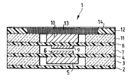
- the single figure shows a cross section through a coupling point of the switching matrix.
- the switching matrix consists of a large number of coupling points 1, preferably arranged in a matrix, for the sake of clarity, only one coupling point 1 is shown in cross section in FIG.
- a mechanically flexible film 2 preferably serves as the base of the switching matrix.
- a mechanically stable film 3 is applied to the mechanically flexible film 2.
- the two films 2, 3 can be glued together or finally laminated with the other films.
- the mechanically stable film 3 is opened in the area of the coupling points 1. This can be done, for example, by punching out or other methods known in film technology.
- a mechanically flexible film 4 is applied to the mechanically stable film 3, on the underside of which permanent magnets 5 are attached in the area of the coupling points 1 and on the upper side contact surfaces 6.
- the permanent magnets 5 and the contact surfaces 6 are preferably attached by gluing to the mechanically flexible film 4.
- the dimensions of the permanent magnet 5 are somewhat smaller than the cavities created by the opening of the mechanically stable film 3.
- a mechanically stable film 7 is applied to the mechanically flexible film 4 and is open in the area of the coupling points 1.
- the mechanically stable film 7 is basically constructed in exactly the same way as the mechanically stable film 3.
- a mechanically flexible film 8 is applied to the mechanically stable film 7, on the underside of which in the area of the coupling points 1 contact surfaces 9 and on the upper side of which a ferromagnetic material 10 are fastened.
- the contact surfaces 9 and the ferromagnetic material 10 are preferably attached by gluing.
- the contact surfaces 6, 9 are arranged congruently to one another, it being possible in principle that a plurality of contact surfaces 6, 9 are used instead of one.
- a mechanically stable film 11 is applied to the mechanically flexible film 8 and is open in the area of the coupling points 1.
- the mechanically stable film 11 is constructed in exactly the same way as the mechanically stable films 3, 7 described above.
- the height dimension of the ferromagnetic material 10 can be less than or equal to the height dimension of the mechanically stable film 11.
- On the mechanically stable Foil 11 is a preferably mechanically stable foil 12 applied.
- Coils 13 are embedded or etched into the film 12 in the area of the coupling points.
- the electrical leads 14 of the coils 13 are arranged on the film 12, preferably in a matrix, towards the edges of the switching matrix.
- the function of the switching matrix is explained below. If the coil 13 of a coupling point 1 is selectively excited with appropriate polarity, a magnetic field is built up which magnetizes the ferromagnetic material 10. This results in a magnetic attraction between the permanent magnet and the ferromagnetic material 10. The mechanically flexible foils 4, 8 are bent by the force to such an extent that the contact surfaces 6, 9 touch and switch through the coupling point. If the excitation of the coil 13 is now interrupted, the ferromagnetic material 10 remains in its magnetized state and the coupling point 1 remains switched through. If the contact is to be separated again, the coil 13 is excited with reverse polarity.
- the electrical signal lines, which are connected or disconnected via the contact surfaces 6, 9, are preferably led out as conductor tracks on the mechanically flexible foils 4, 8 to the edges of the switching matrix.
- the distances between the individual coupling points 1 must be selected to be sufficiently large that, on the one hand, magnetic interference is avoided and, on the other hand, the mechanically flexible foils 4, 8 are sufficiently clamped in the region of a coupling point 1 so that the foils 4, 8 deflect the surrounding coupling points 1 at a coupling point 1 are not influenced.
- the individual foils can be glued or laminated together, for example.
- the production by means of foils, which can be processed, for example, from the roll, enables particularly cost-effective production with high throughput.
- a preferred field of application of the switching matrix is the use as a signal-independent, remotely controllable distributor in communication and data technology.
Abstract
Die Erfindung betrifft ein Koppelfeld zur Schaltung elektrischer Signalleitungen, insbesondere in der Kommunikations- und Datentechnik, bestehend aus einer Vielzahl von vorzugsweise matrixförmig angeordneten Koppelpunkten 1 . Dabei wird der einen Kontaktfläche 6 ein Permanentmagnet 5 und der gegenüberliegenden Kontaktfläche 9 ein ferromagnetischer Werkstoff 10 mit einer Spule 13 zugeordnet. Somit wird ein signalunabhängiges, robustes Koppelfeld geschaffen, das sich kompakt und kostengünstig herstellen läßt. Insbesondere bei der Ausführung der Erfindung mittels Folientechnik läßt sich eine besonderes hohe Kompaktheit erzielen. <IMAGE>The invention relates to a switching matrix for switching electrical signal lines, in particular in communication and data technology, consisting of a multiplicity of coupling points 1, preferably arranged in a matrix. In this case, one contact surface 6 is assigned a permanent magnet 5 and the opposite contact surface 9 is assigned a ferromagnetic material 10 with a coil 13. This creates a signal-independent, robust switching matrix that can be produced compactly and inexpensively. Particularly when the invention is implemented by means of film technology, a particularly high degree of compactness can be achieved. <IMAGE>
Description
Die Erfindung betrifft ein Koppelfeld zur Schaltung elektrischer Signalleitungen.The invention relates to a switching matrix for switching electrical signal lines.
Koppelfelder werden vorzugsweise in der Kommunikations- und Datentechnik eingesetzt, wenn eine große Anzahl von Leitungen geschaltet werden muß.Switching networks are preferably used in communication and data technology when a large number of lines have to be switched.
Im allgemeinen werden elektronische Koppelfelder benutzt, die platzsparend als integrierte Schaltungen ausgeführt sind. Diese haben jedoch den Nachteil, nur spezifische Signalarten schalten zu können. Außerdem sind die elektronischen Koppelfelder empfindlich gegenüber elektromagnetischer Störstrahlung (EMV) und großen Temperaturschwankungen. Koppelfelder, die nicht an eine spezifische Signalart gebunden sind, beruhen auf elektrodynamischen, thermischen oder elektrostatischen Eigenschaften. Diese Koppelfelder sind sehr komplex ausgebildet, was sehr hohe Fertigungskosten zur Folge hat. Ähnliches gilt für mikromechanischen Koppelfelder.In general, electronic switching fields are used, which are designed to save space as integrated circuits. However, these have the disadvantage of being able to switch only specific types of signals. In addition, the electronic switching fields are sensitive to electromagnetic interference (EMC) and large temperature fluctuations. Switching fields that are not tied to a specific type of signal are based on electrodynamic, thermal or electrostatic properties. These coupling fields are very complex, which results in very high manufacturing costs. The same applies to micromechanical coupling fields.
Eine weitere Art nicht signalgebundener Koppelfelder sind die bekannten elektromechanischen Koppelfelder. Diese bestehen aus einzelnen Relais, die durch entsprechende Verdrahtung mittels Draht oder Leiterplatten zu Koppelfeldern zusammengefügt werden. Diese Art der Ausführung der Koppelfelder wird insbesondere bei einer großen Anzahl von Koppelpunkten problematisch, da diese dann in verschiedenen Ebenen angeordnet werden müssen. Hierzu müssen große Mengen von Verbindungskabeln und verschiedenen Ansteuermodulen verwendet werden. Außerdem muß bei nicht selbsthaltenden Relais fortlaufend Strom durch die Spule fließen, um den Kontakt geschlossen zu halten. Dies führt zu einer unerwünscht großen Leistungsaufnahme, insbesondere da in vielen Anwendungen die einzelnen Koppelpunkte nur sehr selten geschaltet werden.Another type of switching fields that are not signal-bound are the known electromechanical switching fields. These consist of individual relays that are connected to coupling fields by appropriate wiring using wire or printed circuit boards. This type of implementation of the switching matrix becomes particularly problematic with a large number of coupling points, since these then have to be arranged in different levels. Large quantities of connection cables and various control modules must be used for this. In addition, with non-latching relays, current must flow continuously through the coil to keep the contact closed. This leads to an undesirably large power consumption, especially since in many applications the individual crosspoints are only switched very rarely.
Aus der WO 92/22919 ist ein derartiger dreidimensionaler galvanischer Schalter bekannt, bei dem mittels dreier Positionierachsen kugelförmige Verbindungsmittel bewegt werden. Die kugelförmigen Verbindungsmittel sind abwechselnd leitend bzw. isolierend ausgeführt, so daß der entsprechende Koppelpunkt entweder durchgeschaltet oder geöffnet wird. Dieses bekannte Koppelfeld erlaubt eine kompakte, selbsthaltende Bauweise der Koppelfelder. Nachteilig bei dieser Ausführung ist die aufwendige und kostspielige Mechanik.Such a three-dimensional galvanic switch is known from WO 92/22919 known in which spherical connecting means are moved by means of three positioning axes. The spherical connecting means are alternately made conductive or insulating, so that the corresponding coupling point is either switched through or opened. This well-known switching matrix allows a compact, self-retaining design of the switching matrix. The disadvantage of this design is the complex and costly mechanics.
Der Erfindung liegt von daher das Problem zugrunde, ein robustes, signalartunabhängiges, Koppelfeld zu schaffen, das in kostengünstiger und kompakter Bauweise herzustellen ist.The invention is therefore based on the problem of creating a robust, signal type-independent switching matrix that can be produced in a cost-effective and compact design.
Die Lösung des Problems ergibt sich aus den Patentansprüchen 1 und 2. Vorteilhafte Weiterbildungen der Erfindung sind in den Unteransprüchen erfaßt.The solution to the problem results from patent claims 1 and 2. Advantageous developments of the invention are covered in the subclaims.
Durch die Zuordnung eines Permanentmagneten zu der einen Kontaktfläche und der Zuordnung einer Spule mit ferromagnetischem Werkstoff zu der gegenüberliegenden Kontaktfläche eines jeden Koppelpunktes ergibt sich eine besonders einfache und robuste Ausführung des Koppelfeldes. Durch die selektive Erregung der Spule eines Koppelpunktes wird der zugeordnete ferromagnetische Werkstoff magnetisiert. Bei geeigneter Polung der Erregung kommt es zu einer magnetischen Anziehungskraft zwischen Permanentmagnet und ferromagnetischem Werkstoff und somit der sich gegenüberliegenden Kontaktflächen. Der Koppelpunkt wird also geschlossen. Dieser Zustand verbleibt auch nach Abschalten der Erregung der Spule. Durch Umpolung der Erregung kann der Koppelpunkt wieder geöffnet werden. Weitere vorteilhafte Ausgestaltungen der Erfindung ergeben sich aus den Unteransprüchen. Insbesondere durch die Ausführung des Koppelfeldes mittels Folien ist eine besonders kompakte Bauweise der Koppelfelder möglich. Außerdem erlaubt die Ausführung mittels Folien eine kostengünstige Fertigung der Koppelfelder, da die entsprechend vorverarbeiteten Folien von der Rolle weiterverarbeitbar sind und so ein besonders hoher Durchsatz erreichbar ist.The assignment of a permanent magnet to the one contact surface and the assignment of a coil with ferromagnetic material to the opposite contact surface of each coupling point result in a particularly simple and robust design of the coupling field. The assigned ferromagnetic material is magnetized by the selective excitation of the coil of a coupling point. With a suitable polarity of the excitation there is a magnetic attraction between the permanent magnet and the ferromagnetic material and thus the opposite contact surfaces. The crosspoint is therefore closed. This state remains even after the excitation of the coil is switched off. The coupling point can be opened again by reversing the polarity of the excitation. Further advantageous embodiments of the invention result from the subclaims. A particularly compact design of the switching matrix is possible, in particular, through the design of the switching matrix using foils. In addition, the design using foils allows the coupling fields to be manufactured cost-effectively, since the correspondingly pre-processed foils can be further processed from the roll and a particularly high throughput can thus be achieved.
Die Erfindung wird nachfolgend anhand eines bevorzugten Ausführungsbeispieles näher erläutert. Die einzige Figur zeigt einen Querschnitt durch einen Koppelpunkt des Koppelfeldes.The invention is explained in more detail below on the basis of a preferred exemplary embodiment explained. The single figure shows a cross section through a coupling point of the switching matrix.
Das Koppelfeld besteht aus einer Vielzahl bevorzugt matrixförmig angeordneter Koppelpunkte 1. Übersichtlichkeitshalber ist in der Figur 1 nur ein Koppelpunkt 1 im Querschnitt dargestellt. Als Basis des Koppelfeldes dient vorzugsweise eine mechanisch flexible Folie 2 . Auf die mechanisch flexible Folie 2 wird eine mechanisch stabile Folie 3 aufgebracht. Die beiden Folien 2, 3 können miteinander verklebt werden oder abschließend mit den anderen Folien laminiert werden. Die mechanisch stabile Folie 3 ist im Bereich der Koppelpunkte 1 geöffnet. Dies kann z.B. durch Ausstanzen oder andere in der Folientechnik bekannte Verfahren geschehen. Auf die mechanisch stabile Folie 3 wird eine mechanisch flexible Folie 4 aufgebracht, auf deren Unterseite im Bereich der Koppelpunkte 1 Permanentmagnete 5 und an deren Oberseite Kontaktflächen 6 befestigt sind. Die Befestigung der Permanentmagnete 5 und der Kontaktflächen 6 erfolgt vorzugsweise durch Verkleben mit der mechanisch flexiblen Folie 4 . Die Abmessungen des Permanentmagneten 5 sind etwas kleiner als die durch die Öffnung der mechanisch stabilen Folie 3 entstandenen Hohlräume. Auf die mechanisch flexible Folie 4 ist eine mechanisch stabile Folie 7 aufgebracht, die im Bereich der Koppelpunkte 1 geöffnet ist. Die mechanisch stabile Folie 7 ist prinzipiell genauso aufgebaut wie die mechanisch stabile Folie 3 . Auf der mechanisch stabilen Folie 7 ist eine mechanisch flexible Folie 8 aufgebracht, an deren Unterseite im Bereich der Koppelpunkte 1 Kontaktflächen 9 und an deren Oberseite ein ferromagnetischer Werkstoff 10 befestigt sind. Die Befestigung der Kontaktflächen 9 und des ferromagnetischen Werkstoffes 10 erfolgt vorzugsweise durch Verklebung. Die Kontaktflächen 6, 9 sind deckungsgleich zueinander angeordnet, wobei es prinzipiell auch möglich ist, daß an stelle einer mehrere Kontaktflächen 6, 9 verwendet werden. Auf die mechanisch flexible Folie 8 ist eine mechanisch stabile Folie 11 aufgebracht, die im Bereich der Koppelpunkte 1 geöffnet sind. Die mechanisch stabile Folie 11 ist prinzipiell genauso aufgebaut wie die zuvor beschriebenen mechanisch stabilen Folien 3, 7 . Die Höhenabmessung des ferromagnetischen Werkstoffes 10 kann kleiner bzw. gleich der Höhenabmessung der mechanisch stabilen Folie 11 sein. Auf die mechanisch stabile Folie 11 ist eine vorzugsweise mechanisch stabile Folie 12 aufgebracht. In die Folie 12 sind im Bereich der Koppelpunkte 1 Spulen 13 eingebettet oder eingeätzt. Die elektrischen Zuführungen 14 der Spulen 13 sind auf der Folie 12 vorzugsweise matrixförmig zu den Rändern des Koppelfeldes hin angeordnet.
Nachfolgend wird die Funktion des Koppelfeldes erläutert.
Wird selektiv bei entsprechender Polung die Spule 13 eines Koppelpunktes 1 erregt, so baut sich ein Magnetfeld auf, das den ferromagnetischen Werkstoff 10 magnetisiert. Dadurch kommt es zu einer magnetischen Anziehungskraft zwischen dem Permanentmagnet und dem ferromagnetischen Werkstoff 10 . Durch die Kraft werden die mechanisch flexiblen Folien 4, 8 so weit durchgebogen, daß sich die Kontaktflächen 6, 9 berühren und den Koppelpunkt durchschalten. Wird nun die Erregung der Spule 13 unterbrochen, so verbleibt der ferromagnetische Werkstoff 10 in seinem magnetisierten Zustand, und der Koppelpunkt 1 bleibt durchgeschaltet. Soll der Kontakt wieder getrennt werden, erregt man die Spule 13 mit umgekehrter Polung. Die elektrischen Signalleitungen, die über die Kontaktflächen 6, 9 miteinander verbunden bzw. getrennt werden, werden vorzugsweise als Leiterbahnen auf den mechanisch flexiblen Folien 4, 8 zu den Rändern des Koppelfeldes herausgeführt. Die Abstände zwischen den einzelnen Koppelpunkten 1 müssen ausreichend groß gewählt werden, daß zum einen eine magnetische Beeinflussung vermieden wird und zum anderen die mechanisch flexiblen Folien 4, 8 im Bereich eines Koppelpunktes 1 ausreichend eingespannt sind, so daß durch die Durchbiegung der Folien 4, 8 an einem Koppelpunkt 1 die umliegenden Koppelpunkte 1 nicht beeinflußt werden. Prinzipiell ist es auch möglich, den Permanentmagneten 5 als Kontaktfläche 6 zu verwenden oder aber den Permanentmagneten 5 direkt unter der Kontaktfläche 6 anzuordnen. Dadurch kann die Kompaktheit des Koppelfeldes zusätzlich erhöht werden. Wie schon zuvor angedeutet, können die einzelnen Folien miteinander z.B. verklebt oder laminiert werden. Durch die Herstellung mittels Folien, die z.B. von der Rolle verarbeitet werden können, ist eine besonders kostengünstige Produktion mit hohem Durchsatz möglich. Ein bevorzugtes Anwendungsfeld des Koppelfeldes ist die Verwendung als signalunabhängiger, fernsteuerbarer Verteiler in der Kommunikations- und Datentechnik.The switching matrix consists of a large number of coupling points 1, preferably arranged in a matrix, for the sake of clarity, only one coupling point 1 is shown in cross section in FIG. A mechanically flexible film 2 preferably serves as the base of the switching matrix. A mechanically
The function of the switching matrix is explained below.
If the
- 11
- KoppelpunktCrosspoint
- 22nd
- mechanisch flexible Foliemechanically flexible film
- 33rd
- mechanisch stabile Foliemechanically stable film
- 44th
- mechanisch flexible Foliemechanically flexible film
- 55
- PermanentmagnetPermanent magnet
- 66
- KontaktflächeContact area
- 77
- mechanisch stabile Foliemechanically stable film
- 88th
- mechanisch flexible Foliemechanically flexible film
- 99
- KontaktflächeContact area
- 1010th
- ferromagnetischer Werkstoffferromagnetic material
- 1111
- mechanisch stabile Foliemechanically stable film
- 1212th
- mechanisch stabile Foliemechanically stable film
- 1313
- SpuleKitchen sink
- 1414
- elektrische Zuführungelectrical feed
Claims (11)
Priority Applications (1)
| Application Number | Priority Date | Filing Date | Title |
|---|---|---|---|
| BR9710461A BR9710461A (en) | 1996-07-30 | 1997-07-09 | Process for the preparation of polyurethane foams semi-rigid open cell polyurethane foams and isocyanate reactive composition |
Applications Claiming Priority (2)
| Application Number | Priority Date | Filing Date | Title |
|---|---|---|---|
| DE19529974 | 1995-08-16 | ||
| DE19529974A DE19529974C1 (en) | 1995-08-16 | 1995-08-16 | Switching matrix network for electrical lines |
Publications (3)
| Publication Number | Publication Date |
|---|---|
| EP0758792A2 true EP0758792A2 (en) | 1997-02-19 |
| EP0758792A3 EP0758792A3 (en) | 1998-05-13 |
| EP0758792B1 EP0758792B1 (en) | 2001-10-17 |
Family
ID=7769515
Family Applications (1)
| Application Number | Title | Priority Date | Filing Date |
|---|---|---|---|
| EP96112250A Expired - Lifetime EP0758792B1 (en) | 1995-08-16 | 1996-07-30 | Connection network |
Country Status (12)
| Country | Link |
|---|---|
| US (1) | US5742012A (en) |
| EP (1) | EP0758792B1 (en) |
| JP (1) | JPH09120746A (en) |
| CN (1) | CN1148256A (en) |
| AT (1) | ATE207237T1 (en) |
| BR (1) | BR9603444A (en) |
| CA (1) | CA2182931C (en) |
| DE (2) | DE19529974C1 (en) |
| DK (1) | DK0758792T3 (en) |
| ES (1) | ES2166852T3 (en) |
| MX (1) | MX9603441A (en) |
| PT (1) | PT758792E (en) |
Families Citing this family (7)
| Publication number | Priority date | Publication date | Assignee | Title |
|---|---|---|---|---|
| US5921382A (en) * | 1998-09-30 | 1999-07-13 | Datahand Systems, Inc | Magnetically enhanced membrane switch |
| US6410360B1 (en) | 1999-01-26 | 2002-06-25 | Teledyne Industries, Inc. | Laminate-based apparatus and method of fabrication |
| US6366186B1 (en) * | 2000-01-20 | 2002-04-02 | Jds Uniphase Inc. | Mems magnetically actuated switches and associated switching arrays |
| AUPQ824700A0 (en) | 2000-06-20 | 2000-07-13 | Alcatel | Bi-stable microswitch including magnetic latch |
| US20020075108A1 (en) * | 2000-12-15 | 2002-06-20 | Ward Lester G. | Method of remotely actuating a membrane switch by attractive or repulsive magnetic force |
| AU784864B2 (en) * | 2001-03-15 | 2006-07-13 | Micro Relay Holdings Pty Ltd | Telecommunication relay array for DSL network configuration |
| BE1021760B1 (en) * | 2013-09-26 | 2016-01-15 | Niko Nv | ELECTROMECHANICAL RELAY |
Citations (2)
| Publication number | Priority date | Publication date | Assignee | Title |
|---|---|---|---|---|
| FR2209999A1 (en) * | 1972-12-07 | 1974-07-05 | Int Standard Electric Corp | |
| FR2524698A1 (en) * | 1982-03-31 | 1983-10-07 | Nippon Mektron Kk | TOUCH KEYBOARD |
Family Cites Families (7)
| Publication number | Priority date | Publication date | Assignee | Title |
|---|---|---|---|---|
| DE2633201A1 (en) * | 1976-07-23 | 1978-01-26 | Siemens Ag | Rectifier switching point for communication exchanges - has bistable relays in series with rectifier, with one pick=up winding and two release windings |
| DE3334708A1 (en) * | 1983-09-24 | 1985-04-11 | Preh, Elektrofeinmechanische Werke Jakob Preh Nachf. Gmbh & Co, 8740 Bad Neustadt | FILM KEYBOARD |
| US5121091A (en) * | 1989-09-08 | 1992-06-09 | Matsushita Electric Industrial Co., Ltd. | Panel switch |
| SE468693B (en) * | 1991-06-17 | 1993-03-01 | Ericsson Telefon Ab L M | GALVANIC CLUTCH DEVICE |
| US5616897A (en) * | 1993-06-30 | 1997-04-01 | Weber; Michael R. | Flexible keyboard |
| US5561278A (en) * | 1994-09-16 | 1996-10-01 | Rutten; Phillip | Membrane switch |
| US5557079A (en) * | 1995-07-03 | 1996-09-17 | Motorola, Inc. | Electronic device with shielded keypad interface |
-
1995
- 1995-08-16 DE DE19529974A patent/DE19529974C1/en not_active Expired - Fee Related
-
1996
- 1996-07-30 ES ES96112250T patent/ES2166852T3/en not_active Expired - Lifetime
- 1996-07-30 DE DE59607931T patent/DE59607931D1/en not_active Expired - Fee Related
- 1996-07-30 AT AT96112250T patent/ATE207237T1/en not_active IP Right Cessation
- 1996-07-30 PT PT96112250T patent/PT758792E/en unknown
- 1996-07-30 EP EP96112250A patent/EP0758792B1/en not_active Expired - Lifetime
- 1996-07-30 DK DK96112250T patent/DK0758792T3/en active
- 1996-08-08 CA CA002182931A patent/CA2182931C/en not_active Expired - Fee Related
- 1996-08-15 BR BR9603444A patent/BR9603444A/en not_active Application Discontinuation
- 1996-08-15 JP JP8215622A patent/JPH09120746A/en active Pending
- 1996-08-16 CN CN96111517A patent/CN1148256A/en active Pending
- 1996-08-16 MX MX9603441A patent/MX9603441A/en not_active IP Right Cessation
- 1996-09-03 US US08/707,131 patent/US5742012A/en not_active Expired - Lifetime
Patent Citations (2)
| Publication number | Priority date | Publication date | Assignee | Title |
|---|---|---|---|---|
| FR2209999A1 (en) * | 1972-12-07 | 1974-07-05 | Int Standard Electric Corp | |
| FR2524698A1 (en) * | 1982-03-31 | 1983-10-07 | Nippon Mektron Kk | TOUCH KEYBOARD |
Also Published As
| Publication number | Publication date |
|---|---|
| US5742012A (en) | 1998-04-21 |
| ATE207237T1 (en) | 2001-11-15 |
| MX9603441A (en) | 1997-03-29 |
| CA2182931C (en) | 2002-06-25 |
| PT758792E (en) | 2002-04-29 |
| ES2166852T3 (en) | 2002-05-01 |
| DE19529974C1 (en) | 1996-10-24 |
| EP0758792A3 (en) | 1998-05-13 |
| DK0758792T3 (en) | 2002-02-04 |
| CA2182931A1 (en) | 1997-02-17 |
| BR9603444A (en) | 1998-05-12 |
| EP0758792B1 (en) | 2001-10-17 |
| JPH09120746A (en) | 1997-05-06 |
| DE59607931D1 (en) | 2001-11-22 |
| CN1148256A (en) | 1997-04-23 |
Similar Documents
| Publication | Publication Date | Title |
|---|---|---|
| DE60016692T2 (en) | Non-volatile MEMS micro-relays with magnetic actuators | |
| DE69632159T2 (en) | Device for controlling the impedance of electrical contacts | |
| EP0712267B1 (en) | Modular control equipment with field bus integrated connection | |
| DE10393867B4 (en) | Multi-layer touch display based on electromagnetic actuators | |
| DE2649374A1 (en) | CONTACT DEVICE AND METHOD OF MANUFACTURING THE SAME | |
| EP0780004A1 (en) | Circuit with a chip card module and a coil connected therewith | |
| EP2338207A1 (en) | Rfid transponder antenna | |
| DE102011079357B4 (en) | operating device | |
| EP0557608A1 (en) | Coil assembly | |
| EP0758792B1 (en) | Connection network | |
| EP1080503B1 (en) | Piezoelectric bending transducer and a module made of a plurality of piezoelectric bending transducers | |
| DE602004001989T2 (en) | ELECTROMAGNETIC RELAY | |
| EP1380038B1 (en) | Passive magnetic position sensor | |
| DE102016216330A1 (en) | Flexible coil arrangement for a magnetoelectric displacement sensor, displacement sensor and manufacturing method | |
| EP0217082A1 (en) | Lead frame and method for producing an electronic element having such a lead frame | |
| EP0494436A2 (en) | Testing device | |
| DE10043549C1 (en) | Microswitch and method for its manufacture | |
| EP2071293B1 (en) | Position sensor | |
| EP2230486B1 (en) | Position sensor | |
| EP1835552A1 (en) | Piezoelectric device | |
| EP2048782B1 (en) | Switching device for a motor vehicle that can be operated | |
| DE2114930A1 (en) | Magnetic head | |
| WO2007104528A1 (en) | Switch arrangement with a plurality of switches arranged in the form of a matrix and method for switching switches arranged in the form of a matrix | |
| DE10349100A1 (en) | Multiple point raster for tactile display uses piezoelectric actuators which bend when energized and move knee-joint levers with flexures pushing round-headed pins from retracted to extended position | |
| DE2604526C3 (en) | Integrated switch device |
Legal Events
| Date | Code | Title | Description |
|---|---|---|---|
| PUAI | Public reference made under article 153(3) epc to a published international application that has entered the european phase |
Free format text: ORIGINAL CODE: 0009012 |
|
| AK | Designated contracting states |
Kind code of ref document: A2 Designated state(s): AT BE CH DE DK ES FI FR GB GR IE IT LI NL PT SE |
|
| PUAL | Search report despatched |
Free format text: ORIGINAL CODE: 0009013 |
|
| AK | Designated contracting states |
Kind code of ref document: A3 Designated state(s): AT BE CH DE DK ES FI FR GB GR IE IT LI NL PT SE |
|
| 17P | Request for examination filed |
Effective date: 19980411 |
|
| 17Q | First examination report despatched |
Effective date: 19991214 |
|
| RAP1 | Party data changed (applicant data changed or rights of an application transferred) |
Owner name: KRONE GMBH |
|
| GRAG | Despatch of communication of intention to grant |
Free format text: ORIGINAL CODE: EPIDOS AGRA |
|
| GRAG | Despatch of communication of intention to grant |
Free format text: ORIGINAL CODE: EPIDOS AGRA |
|
| GRAH | Despatch of communication of intention to grant a patent |
Free format text: ORIGINAL CODE: EPIDOS IGRA |
|
| GRAH | Despatch of communication of intention to grant a patent |
Free format text: ORIGINAL CODE: EPIDOS IGRA |
|
| GRAA | (expected) grant |
Free format text: ORIGINAL CODE: 0009210 |
|
| AK | Designated contracting states |
Kind code of ref document: B1 Designated state(s): AT BE CH DE DK ES FI FR GB GR IE IT LI NL PT SE |
|
| REF | Corresponds to: |
Ref document number: 207237 Country of ref document: AT Date of ref document: 20011115 Kind code of ref document: T |
|
| REG | Reference to a national code |
Ref country code: CH Ref legal event code: NV Representative=s name: MICHELI & CIE INGENIEURS-CONSEILS Ref country code: CH Ref legal event code: EP |
|
| REG | Reference to a national code |
Ref country code: IE Ref legal event code: FG4D Free format text: GERMAN |
|
| REF | Corresponds to: |
Ref document number: 59607931 Country of ref document: DE Date of ref document: 20011122 |
|
| REG | Reference to a national code |
Ref country code: GB Ref legal event code: IF02 |
|
| REG | Reference to a national code |
Ref country code: DK Ref legal event code: T3 |
|
| GBT | Gb: translation of ep patent filed (gb section 77(6)(a)/1977) |
Effective date: 20020116 |
|
| ET | Fr: translation filed | ||
| REG | Reference to a national code |
Ref country code: PT Ref legal event code: SC4A Free format text: AVAILABILITY OF NATIONAL TRANSLATION Effective date: 20020115 |
|
| REG | Reference to a national code |
Ref country code: ES Ref legal event code: FG2A Ref document number: 2166852 Country of ref document: ES Kind code of ref document: T3 |
|
| REG | Reference to a national code |
Ref country code: GR Ref legal event code: EP Ref document number: 20020400158 Country of ref document: GR |
|
| PGFP | Annual fee paid to national office [announced via postgrant information from national office to epo] |
Ref country code: PT Payment date: 20020626 Year of fee payment: 7 |
|
| PGFP | Annual fee paid to national office [announced via postgrant information from national office to epo] |
Ref country code: FR Payment date: 20020723 Year of fee payment: 7 Ref country code: AT Payment date: 20020723 Year of fee payment: 7 |
|
| PGFP | Annual fee paid to national office [announced via postgrant information from national office to epo] |
Ref country code: BE Payment date: 20020724 Year of fee payment: 7 |
|
| PGFP | Annual fee paid to national office [announced via postgrant information from national office to epo] |
Ref country code: NL Payment date: 20020725 Year of fee payment: 7 Ref country code: ES Payment date: 20020725 Year of fee payment: 7 Ref country code: CH Payment date: 20020725 Year of fee payment: 7 |
|
| PGFP | Annual fee paid to national office [announced via postgrant information from national office to epo] |
Ref country code: GR Payment date: 20020730 Year of fee payment: 7 |
|
| PGFP | Annual fee paid to national office [announced via postgrant information from national office to epo] |
Ref country code: DE Payment date: 20020731 Year of fee payment: 7 |
|
| PLBE | No opposition filed within time limit |
Free format text: ORIGINAL CODE: 0009261 |
|
| STAA | Information on the status of an ep patent application or granted ep patent |
Free format text: STATUS: NO OPPOSITION FILED WITHIN TIME LIMIT |
|
| 26N | No opposition filed | ||
| PG25 | Lapsed in a contracting state [announced via postgrant information from national office to epo] |
Ref country code: AT Free format text: LAPSE BECAUSE OF NON-PAYMENT OF DUE FEES Effective date: 20030730 |
|
| PG25 | Lapsed in a contracting state [announced via postgrant information from national office to epo] |
Ref country code: LI Free format text: LAPSE BECAUSE OF NON-PAYMENT OF DUE FEES Effective date: 20030731 Ref country code: ES Free format text: LAPSE BECAUSE OF NON-PAYMENT OF DUE FEES Effective date: 20030731 Ref country code: CH Free format text: LAPSE BECAUSE OF NON-PAYMENT OF DUE FEES Effective date: 20030731 Ref country code: BE Free format text: LAPSE BECAUSE OF NON-PAYMENT OF DUE FEES Effective date: 20030731 |
|
| BERE | Be: lapsed |
Owner name: *KRONE G.M.B.H. Effective date: 20030731 |
|
| PG25 | Lapsed in a contracting state [announced via postgrant information from national office to epo] |
Ref country code: PT Free format text: LAPSE BECAUSE OF NON-PAYMENT OF DUE FEES Effective date: 20040131 |
|
| PG25 | Lapsed in a contracting state [announced via postgrant information from national office to epo] |
Ref country code: NL Free format text: LAPSE BECAUSE OF NON-PAYMENT OF DUE FEES Effective date: 20040201 |
|
| PG25 | Lapsed in a contracting state [announced via postgrant information from national office to epo] |
Ref country code: DE Free format text: LAPSE BECAUSE OF NON-PAYMENT OF DUE FEES Effective date: 20040203 |
|
| PG25 | Lapsed in a contracting state [announced via postgrant information from national office to epo] |
Ref country code: GR Free format text: LAPSE BECAUSE OF NON-PAYMENT OF DUE FEES Effective date: 20040205 |
|
| REG | Reference to a national code |
Ref country code: CH Ref legal event code: PL |
|
| PG25 | Lapsed in a contracting state [announced via postgrant information from national office to epo] |
Ref country code: FR Free format text: LAPSE BECAUSE OF NON-PAYMENT OF DUE FEES Effective date: 20040331 |
|
| NLV4 | Nl: lapsed or anulled due to non-payment of the annual fee |
Effective date: 20040201 |
|
| REG | Reference to a national code |
Ref country code: FR Ref legal event code: ST Ref country code: PT Ref legal event code: MM4A Free format text: LAPSE DUE TO NON-PAYMENT OF FEES Effective date: 20040131 |
|
| PGFP | Annual fee paid to national office [announced via postgrant information from national office to epo] |
Ref country code: GB Payment date: 20040716 Year of fee payment: 9 |
|
| PGFP | Annual fee paid to national office [announced via postgrant information from national office to epo] |
Ref country code: FI Payment date: 20040722 Year of fee payment: 9 |
|
| PGFP | Annual fee paid to national office [announced via postgrant information from national office to epo] |
Ref country code: SE Payment date: 20040723 Year of fee payment: 9 |
|
| PGFP | Annual fee paid to national office [announced via postgrant information from national office to epo] |
Ref country code: DK Payment date: 20040727 Year of fee payment: 9 |
|
| PGFP | Annual fee paid to national office [announced via postgrant information from national office to epo] |
Ref country code: IE Payment date: 20040729 Year of fee payment: 9 |
|
| REG | Reference to a national code |
Ref country code: ES Ref legal event code: FD2A Effective date: 20030731 |
|
| PG25 | Lapsed in a contracting state [announced via postgrant information from national office to epo] |
Ref country code: FI Free format text: LAPSE BECAUSE OF NON-PAYMENT OF DUE FEES Effective date: 20050710 |
|
| PG25 | Lapsed in a contracting state [announced via postgrant information from national office to epo] |
Ref country code: IT Free format text: LAPSE BECAUSE OF NON-PAYMENT OF DUE FEES Effective date: 20050730 Ref country code: GB Free format text: LAPSE BECAUSE OF NON-PAYMENT OF DUE FEES Effective date: 20050730 |
|
| PG25 | Lapsed in a contracting state [announced via postgrant information from national office to epo] |
Ref country code: SE Free format text: LAPSE BECAUSE OF NON-PAYMENT OF DUE FEES Effective date: 20050731 |
|
| PG25 | Lapsed in a contracting state [announced via postgrant information from national office to epo] |
Ref country code: IE Free format text: LAPSE BECAUSE OF NON-PAYMENT OF DUE FEES Effective date: 20050801 Ref country code: DK Free format text: LAPSE BECAUSE OF NON-PAYMENT OF DUE FEES Effective date: 20050801 |
|
| EUG | Se: european patent has lapsed | ||
| GBPC | Gb: european patent ceased through non-payment of renewal fee |
Effective date: 20050730 |
|
| REG | Reference to a national code |
Ref country code: DK Ref legal event code: EBP |
|
| REG | Reference to a national code |
Ref country code: IE Ref legal event code: MM4A |