EP0758514B1 - Colour transformation process and a colour video system - Google Patents
Colour transformation process and a colour video system Download PDFInfo
- Publication number
- EP0758514B1 EP0758514B1 EP96902260A EP96902260A EP0758514B1 EP 0758514 B1 EP0758514 B1 EP 0758514B1 EP 96902260 A EP96902260 A EP 96902260A EP 96902260 A EP96902260 A EP 96902260A EP 0758514 B1 EP0758514 B1 EP 0758514B1
- Authority
- EP
- European Patent Office
- Prior art keywords
- colour
- valence
- primary
- valences
- color
- Prior art date
- Legal status (The legal status is an assumption and is not a legal conclusion. Google has not performed a legal analysis and makes no representation as to the accuracy of the status listed.)
- Expired - Lifetime
Links
Images


Classifications
-
- H—ELECTRICITY
- H04—ELECTRIC COMMUNICATION TECHNIQUE
- H04N—PICTORIAL COMMUNICATION, e.g. TELEVISION
- H04N9/00—Details of colour television systems
- H04N9/64—Circuits for processing colour signals
- H04N9/646—Circuits for processing colour signals for image enhancement, e.g. vertical detail restoration, cross-colour elimination, contour correction, chrominance trapping filters
-
- H—ELECTRICITY
- H04—ELECTRIC COMMUNICATION TECHNIQUE
- H04N—PICTORIAL COMMUNICATION, e.g. TELEVISION
- H04N9/00—Details of colour television systems
- H04N9/64—Circuits for processing colour signals
- H04N9/67—Circuits for processing colour signals for matrixing
Definitions
- the invention relates to a method for color transformation of the color valences of pixels of a color video system in which each color valence is due to components of a color vector within an achromatic dot
- Color valence range can be represented by the primary valences on the input side
- Signal source is defined, and in the image side for the representation of the pixels
- Primary valences are used, whose color valence range also corresponds to Includes achromatic dot, with at least one color valence of this color valence range lies outside the color valence range of the input-side primary valences and one Transformation for generating primary valences on the image side (R ", G", B ") related components is performed and image-side components more negative Intensity can be suppressed on occurrence.
- the invention further relates to Color video system for displaying colored pixels with an input circle to the Generation or transfer of associated primary valences Color value signals for a color valence range that contains an achromatic point, with a Image generating device for generating the pixels of a color video image due to primary valences on the image side, whose color valence range is the achromatic point and at least one color valence outside the color valence range of the input side Contains primary valences, as well as a matrix circuit that is connected between the input circuit and the image generation device is connected and input-side color value signals in image-side color value signals for the pixels of the image generation device transformed.
- Color transformations in television reception for the adaptation of broadcast Color value signals to the phosphors of the picture tubes are, for example, from the book by Heinwig Lang, "Colorimetry and Color TV", R. Oldenbourg Verlag, Kunststoff, 1978, known
- the matrix transformations given there in the color space can be used, for example, when a video image with primary valences is sent according to the FCC standard and is displayed in the correct color on a picture tube should be, which is provided with phosphors according to the EBU standard.
- the FCC standard and the EBU standard differ essentially in the green area, what a Color adjustment necessary for the correct representation.
- the object of the invention is a method and a corresponding color video system to create a range of colors that is more accessible than given by input-side color value signals for the representation of the colors in to use a video system with little effort.
- a fictitious primary valence system is used. This allows a defined implementation of the input color valences in a color valence system with different hues and different color saturations. Only through the further Transformation takes place the adaptation of those generated in the fictitious primary valence system Color valences on the image-side primary valences for display.
- the method can be used for a better color display in advertising realize such a laser projection system, for example, that the To be implemented simultaneously with the processing of Commercials are carried out using computers.
- the computer program all colors according to a matrix transformation from the Primary valences with which the commercial was recorded on the one Laser projection system implemented primary valences on the input side and only when processing for certain products or a scene section more saturated colors are to be used in the fictitious primary valence system Implementation of the pixels according to the inventive method.
- For the means of alienation often used in advertising are then available
- more degrees of freedom are available through new colors.
- the method according to the invention also allows the use of the same Color value signals for different receivers that are different Have primary valence systems for color representation.
- Color valences in a larger one Tint range added and for the standard television sets whose displayable color valence range is determined by the screen phosphor information, for example, can also be processed on a sideband accommodate a receiving device with a larger displayable Color valence range indicate when a pixel has a color in one, for example is represented by a standard fictitious primary valence system. In this The receiving device can then do the conversion and transformation accordingly respectively.
- This example shows that the invention not only achieves the object, but in unexpectedly enriched the technology by even watching TV for different television sets of different standards allowed.
- the method can therefore be used in a variety of ways.
- One of the possible uses is furthermore, deni the user of a video device the choice of the fictional Primary valence system itself, for example, using a remote control on a large scale to be left with, so that, depending on the taste, he becomes more saturated or can set slight color distortion.
- a very free choice of the fictitious primary valences lead to color-cast images.
- a degree of freedom in the choice of the fictitious primary valence system becomes one Color castness avoided, since a white tone on the input side is also the same White tone is displayed.
- the method according to the invention differs from that in the early days of Color television standard choice of different amplitudes of the Color value signals, which could result in a color cast that, above all expressed uncomfortably in the shades of white.
- a matrix for implementation also enables a very technical one simple implementation of the method, if according to a preferred development of the invention in which only a single matrix transformation is used for the transformation a matrix is carried out, which is the product of the matrix for implementation with a matrix for the transformation from the fictitious pimarvalence system (R ', G', B ') to the image-side primary valence system (R ", G", B ") results
- fictitious primary valences are fixed to color valences that have the same hue as the input-side primary valences but have an increased saturation for at least one of the input-side primary valences.
- larger color falsifications can also be avoided and the user of a video device in which the method according to the invention is used can enjoy richer colors without the quality of the television picture being influenced due to incorrectly displayed color tones.
- a circuit for implementing on the input side Primary valences related color value signals related to fictitious primary valences Color value signals are provided whose color valence range is at least one Color valence outside the color valence range of the primary valences and contains within the color valence range of the image-side primary valences, whereby by means of the color value signals of at least one primary valence on the input side Color value signals for the at least one color valence outside the color valence range of the input-side primary valences can be implemented, and the matrix circuit for Transformation of the color value signals related to the fictitious primary valences to the primary valences on the image side.
- the color video system according to the invention all has to carry out the method necessary circuit parts.
- it is characterized by a special simple construction on A matrix circuit is expediently already in one Color video system with different for the representation of the input signals Include primary valences for the correct color image of the pixels.
- An inventive In this respect, color video system is no more complex than a color video system According to the state of the art.
- the color video system according to the invention then requires just an additional circuit to implement, the effort, like that later shown embodiments will still show, is low or in a suitable Choice of implementation even disappears.
- color-cast images are avoided by the Circuit for converting the input color value signals to the fictitious ones
- Primary valences are designed so that a color valence of the achromatic point on the image side the input color valency can be represented.
- This training is made possible by separating the implementation from the subsequent color valence-correct transformation also different, for example Settings to be selected by the user for various types of carrying out the Procedure, as a separate circuit for the implementation also switching to allows different desired conditions if different Circuits upstream of the matrix circuit are possible.
- the additional circuitry disappears Expenditure compared to a television set according to the prior art completely, which does not use the method according to the invention, since the Matrix circuit contains the circuit for implementation by working for a Matrix transformation is designed with a single transformation matrix that the Product from the matrix for the matrix transformation of the implementation and the matrix to transform the color value signals from the fictitious primary valence system to the primary valences on the image side.
- the circuit for Implementation controllable for different fictitious primary valences In another preferred development of the invention, the circuit for Implementation controllable for different fictitious primary valences.
- Color video system for example, the option to be opened whether he the picture with regard to the color value signals sent on the input side, or want to make use of various possible saturation levels, for example.
- This option not only increases comfort, but also enables one Standardization because you don't need different video systems when you on the one hand wants to view pictures in accordance with the input television norm and on the other hand the video system for displaying otherwise unavailable color valences, for example in the example mentioned at the beginning of advertising. This standardization also advantageously reduces the necessary Expenditure.
- the circuit for different selectable fictitious primary valences controllable resistors on by control voltages or currents that can be applied to the circuit are changeable.
- suppression circuits are provided for negative image-side color value signals, each for each color value signal contain a voltage divider consisting of a diode and a resistor, the Voltage divider on the diode side against the threshold voltages of the diodes compensating potential are switched.
- the illustrated version of the suppression circuits with a resistor and a diode is also not very expensive. It even enables appropriate selection of resistance, a logarithmic truncation, so that at the limits of the displayable color valence range, at which otherwise negative Larger color changes can still be detected when color value signals occur. Through these features of the training, the Image quality increased.
- Fig. 1 shows a color video system in which 10 video signals in an input circuit generated or adopted. These generally refer to Screen phosphor with the associated primary valences (R), (G), (B), for example according to the color standard EBU or FCC. With common video systems the corresponding color value signals for color control on a picture tube transferred as an image generation device. The usual gamma pre-equalization in a color video system has on the colorimetrically linear Connection no influence. You only get a true-to-color image if the picture tube complies with the same standard as the primary valences (R), (G), (B) for the color value signals, from the input circuit 10.
- FIG. 1 an image generating device 12 is shown, the color correct reproduces if in these color value signals according to other primary valences (R “), (G"), (B ") can be entered
- Technology usually uses a matrix circuit 14 which carries the color value signals from the primary valences (R), (G), (B) from the input circuit 10 to the Color value signals of the other primary valences (R “), (G"), (B ") are transformed.
- Circuit 15 To generate the input signals for the matrix circuit 14 there is also one Circuit 15 provided for implementation according to the inventive method, which is subsequently explained in more detail in connection with FIGS. 2 and 3. Essentially, the circuit produces 15 colors of increased saturation with respect to the fictitious primary valences (R '), (G') and (B ').
- the components of the matrix circuit 14 that determine the matrix usually Resistances are held here according to the fictitious primary valences (R '), (G'), (B ') according to the state of the art according to the primary valences (R), (G) on the input side, (B) dimensioned.
- a control circuit 16 is provided which the values of the Coefficient determining resistances in the matrix circuit 14 controls so different saturations over different fictitious primary valences (R '), (G'), (B ') possible are.
- Thermistors are suitable as controllable resistors are heated from the control circuit 16, or also magnetically, for example via the Hall effect changeable resistors from the control circuit 16 with a Magnetic field are applied.
- control circuit 16 is also connected to the circuit 15 Signal conversion connected.
- This connection can also be used in the Circuit 15 performed signal conversion to different fictitious Primary valences (R '), (G') and (B ') can be adjusted, which means that the fictitious primary valences result in different saturations. in the Embodiment of FIG. 1 can thus be via the control circuit 16 set different saturations.
- control circuit 16 was designed so that due to the fictitious primary valences (R '), (G'), (B ') essentially only an increased one Saturation of colors is achieved and color distortions within one remain within the tolerable range. How this can be achieved is shown in FIG. 2 explained in more detail.
- Fig. 2 shows a CIE diagram with the usual coordinates x and y, for the different color valences run from 0 to 1. 2 is a grid with Distances of 0, 1 are drawn in for x and y.
- the usual spectral curve 18 is also shown. With a laser video system the colors are on this spectral curve 18 because lasers are monochromatic.
- Lasers were used for the imaging device 12 in the exemplary embodiment in FIG. 1 used to represent the color of the pixels.
- the used here Wavelengths resulted in a primary valence system, which is shown in FIG Points (R “), (G"), and (B ") are drawn on the spectral curve 18.
- the accessible color valence range is then within the range interrupted by the Lines between the coordinates of the points (R “), (G") and (B ") marked Triangular.
- Fig. 2 denote the intersection points of the connecting straight line with the Spectral color spectrum 18 colors of maximum saturation. However, are available with the Imaging device 12 only those saturations that in Fig. 2 with (R '), (G') and (B ') are designated and by the intersection points of the connecting straight line with the Sides of the color triangle for the image-side primary valences (R "), (G") and (B ") given are.
- the colors do not differ from the primary valences on the input side (R), (G), (B) but from a fictitious primary valence system that passes through these points (R '), (G') and (B ') in the CIE diagram is set in the image side Primary valence system (R “), (G") and (B ") is carried out in the Imaging device 12 colors of the same color but with maximum saturation produce.
- R "), (G") and (B ") is carried out in the Imaging device 12 colors of the same color but with maximum saturation produce.
- the highest possible saturation can be achieved if one for the Imager 12 uses lasers that have wavelengths that pass through the intersections of the connecting straight lines with the spectral color train 18 such an example is shown graphically in FIG. 3.
- the fictitious primary valence system is equal to that primary valence system on the image side can be selected, the then described transformation from the fictitious primary valences (R '), (G'), (B ') to the image-side primary valences (R ", G", B ”) reduced to a one matrix, which is why in a color video system does not have a corresponding circuit for transformation can.
- the input side Color value signals from the primary valence system (R), (G), (B) to the fictitious Primary valences (R '), (G'), (B ') are implemented so that a color valence on one of the coordinates given in FIG. 2 for the input-side primary valences (R), (G), (B) to the coordinate points of the fictitious primary valences (R '), (G') and (B) be implemented.
- the easiest way to implement is the input side Color value signals refer to the fictitious primary valences (R '), (G'), (B '). Than are the components of the color vector in the (R '), (G'), (B ') primary valence system are identical with the components of the color vectors in the primary valence system on the input side Color value signals therefore do not have to be changed. However, with one Any choice also changes the white tone, so it is a color cast of the not always exclude generated image.
- the matrix for the implementation can be determined mathematically in the following way:
- the equation yields three determination equations for the three scaling variables S R , S G , S B , so that these can be clearly determined.
- the color vectors for the fictitious primary valences (R '), (G'), and (B ') in the normal valence system with the components X i , Y i , Z i are clearly defined by where the index i is again a placeholder for the colors R, G, B.
- a matrix can now be created with the components obtained in this way form, which together with the matrix M of the components of the input-side primary valences (R), (G), (B) the matrix searched for via the relationship M -1 M 'for converting the color value signals of the input-side primary valence system (R), (G), (B) to the fictitious primary valence system (R'), (G '), (B').
- the coordinates given in the table can be marked with a Realize imaging device, its lasers as light sources for display the pixels have the wavelengths 647, Inm for red, 514, 5 nm for green and 457, 9 nm for blue.
- (F ') - (w) U [(F) - (w)], where (F) represents a color vector of the input-side primary valences (R), (G) or (B), (F ') represents a color vector of the fictitious primary valences (R'), (G ') or (B') and U is a function , which is converted into (F ') for the specified approach (F).
- the function U can be freely selected to a large extent, so that even non-linear saturation increases can be achieved.
- the color vector resulting from the implementation in primary system for S> 1 may also have negative components, which shows that the implementation as expected from the color valence range of the upstream primary valences (R), (G), (B). Circuitry Negative color value signals continue to cause no problems since the following Transformation from the fictitious primary valences to the image-side primary valences again creates a larger color valence range, which then creates the Color value signals are transformed back to positive and physically meaningful values can be.
- FIG. 4 shows the circuit 20 for converting color value signals in accordance with the given equation. It contains four operational amplifiers 22, 24, 26 and 28 as essential components. Signals with the color values r, g, b are applied to the inverting inputs of the operational amplifiers 22, 24 and 26 via resistors 30, 32 and 34.
- the operational amplifiers 22, 24 and 26 are coupled with controllable resistors 40, 42 and 44.
- the respective resistance ratios of the resistance values of the resistors 40, 42 and 44 and the resistors 30, 32 and 34 determine the gain factor through the operational amplifiers 22, 24 and 26.
- the resistors 30, 32, 34, 40, 42, 44 are designed so that according to the external control there is a gain factor S according to the desired saturation.
- a voltage value is subtracted from the output voltages of the operational amplifiers 22, 24, 26, which, with appropriate dimensioning, corresponds to the term [1 - 1 / S] (r + g + b) (w) corresponds.
- the resistors 50, 52, 54 of the same value are used for summing the color value signals r, g and b.
- the gain of amplifier 28, which depends on the resistance of a first controllable resistor 56, is designed to be (1 - 1 / S).
- the resistors 46, 47, 48 are used for damping in accordance with the components L R , L G and L B of the color vector (w).
- the gains of the operational amplifiers 22, 24, 26 and 28 and here controllable via negative feedback resistors 40, 42, 44, 56 are very complex in a video system at the high frequencies required. Therefore, a standard circuit using operational amplifiers and controllable resistors is preferred. Controllable resistors can be set, for example via a magnetic field or via a heater. However, the gains can also be controlled digitally if a circuit according to FIG. 5 is used for the resistors 40, 42, 44, 56. The example of FIG. 5 is designed for 16 levels of resistance values corresponding to a 4 bit representation for s.
- resistors 60, 62, 64, 66 and 68 are formed by resistors 60, 62, 64, 66 and 68 connected in series, the resistors 62, 64, 66 and 68 being connected across the drain-source path of field effect transistors 70, 72, 74, 76 can be short-circuited.
- field effect transistors are available as analog switches from Texas Instruments together with control electronics as integrated circuits under the designations TL 182C, TL 185C, TL 188C or TL 191 C, but with the calculation of resistors 62, 64, 66 and 68 the right high resistance of the drain-source path of over 100 ⁇ must be taken into account.
- Such a connection according to FIGS. 4 and 5 permits an increase in the saturation in 16 stages, the stages switched by a digitally represented binary value become. This can, for example, from the voltage drop at the tap Potentiometers can be obtained via an analog-digital converter.
- the Such circuits can be expanded to more than 16 stages appropriate wiring with more field effect transistors and resistors in achieve the same way.
- FIG. 6 shows how the circuit 20 according to FIG. 4 can be inserted into a matrix circuit 14.
- the signals for the color values r, g, b are present at the inputs of the circuit 20, the factor S of which is intended as a binary value via logic signals for increasing the saturation at the inputs denoted by 2 0 , 2 1 , 2 2 , 2 3 .
- the signals converted by the circuit 20 in accordance with the given equation are then passed to a matrix circuit 80 which is constructed according to the prior art in such a way that from color value signals of the input-side primary valences (R, G, B) to color value signals of the image-side primary valences (R ""G", B ") is transformed to display colors in the image generation device 12.
- the reversal of the sign of the color value signals for the color values r, g, b is taken into account by the circuit 20 in the matrix circuit 80.
- a suppression circuit is off at each output of the matrix circuit 80
- a resistor 82, 84, 86 and a diode 92, 94, 96 are provided each existing voltage divider. These suppression circuits suppress voltages of wrong polarity, which arise when the increase in saturation from the hue range of the primary valences (R ", G", B ”) leads out the spanned color range. This could be ex iel be possible with a very large S, as can be seen from FIG. 2 by the blue primary valence, for which only a small increase in saturation is possible due to the limited color valence range.
- the diodes 92, 94, 96 are connected here to a counter potential of 0.7 volts, that the threshold voltage of those used in the embodiment Silicon diodes 92, 94, 96 is.
- the control of the diodes 92, 94, 96 shown ensures that the output signals of the matrix circuit 14 at negative Output signals of the matrix circuit 80 logarithmically asymptotically to zero go.
- the use of the logarithmic behavior is determined by the interpretation of the Resistors 82, 84 and 86 in connection with the diode characteristics of the diodes 92, 94 and 96 determined in a known manner.
Abstract
Description
Die Erfindung bezieht sich auf ein Verfahren zur Farbtransformation der Farbvalenzen von Bildpunkten eines Farbvideosystems, bei dem jede Farbvalenz durch Komponenten eines Farbvektors innerhalb eines einen Unbuntpunkt einschließenden Farbvalenzbereichs darstellbar ist, der durch eingangsseitige Primärvalenzen einer Signalquelle festgelegt ist, und bei dem für die Darstellung der Bildpunkte bildseitige Primärvalenzen verwendet werden, deren Farbvalenzbereich ebenfalls den Unbuntpunkt einschließt, wobei mindestens eine Farbvalenz dieses Farbvalenzbereichs außerhalb des Farbvalenzbereichs der eingangsseitigen Primärvalenzen liegt und eine Transformation zum Erzeugen von auf bildseitige Primärvalenzen (R", G", B") bezogene Komponenten durchgeführt wird und bildseitige Komponenten negativer Intensität bei Auftreten unterdrückt werden. Weiter bezieht sich die Erfindung auf ein Farbvideosystem zur Darstellung farbiger Bildpunkte mit einem Eingangskreis zum Erzeugen bzw. Übernehmen von eingangsseitigen Primärvalenzen zugehörigen Farbwertsignalen für einen Farbvalenzbereich der einen Unbuntpunkt enthält, mit einer Bilderzeugungseinrichtung zur Erzeugung der Bildpunkte eines Farbvideobildes aufgrund von bildseitigen Primärvalenzen, deren Farbvalenzbereich den Unbuntpunkt und mindestens eine Farbvalenz außerhalb des Farbvalenzbereichs der eingangsseitigen Primärvalenzen enthält, sowie einen Matrixschaltkreis, der zwischen den Eingangskreis und die Bilderzeugungseinrichtung geschaltet ist und eingangsseitige Farbwertsignale in bildseitige Farbwertsignale für die Bildpunkte der Bilderzeugungseinrichtung transformiert.The invention relates to a method for color transformation of the color valences of pixels of a color video system in which each color valence is due to components of a color vector within an achromatic dot Color valence range can be represented by the primary valences on the input side Signal source is defined, and in the image side for the representation of the pixels Primary valences are used, whose color valence range also corresponds to Includes achromatic dot, with at least one color valence of this color valence range lies outside the color valence range of the input-side primary valences and one Transformation for generating primary valences on the image side (R ", G", B ") related components is performed and image-side components more negative Intensity can be suppressed on occurrence. The invention further relates to Color video system for displaying colored pixels with an input circle to the Generation or transfer of associated primary valences Color value signals for a color valence range that contains an achromatic point, with a Image generating device for generating the pixels of a color video image due to primary valences on the image side, whose color valence range is the achromatic point and at least one color valence outside the color valence range of the input side Contains primary valences, as well as a matrix circuit that is connected between the input circuit and the image generation device is connected and input-side color value signals in image-side color value signals for the pixels of the image generation device transformed.
Farbtransformationen beim Fernsehempfang zur Anpassung von gesendeten Farbwertsignalen an die Phosphore der Bildröhren sind beispielsweise aus dem Buch von Heinwig Lang, "Farbmetrik und Farbfernsehen", R. Oldenbourg Verlag, München, 1978, bekannte Die dort angegebenen Matrixtransformationen im Farbraum können beispielsweise verwendet werden, wenn ein Videobild mit Primärvalenzen nach der FCC-Norm gesendet wird und farbrichtig auf einer Bildröhre dargestellt werden soll, die mit Phosphoren nach der EBU-Norm versehen ist. Die FCC-Norm und die EBU-Norm unterscheiden sich im wesentlichen im Grünbereich, was eine Farbanpassung zur farbrichtigen Darstellung nötig macht.Color transformations in television reception for the adaptation of broadcast Color value signals to the phosphors of the picture tubes are, for example, from the book by Heinwig Lang, "Colorimetry and Color TV", R. Oldenbourg Verlag, Munich, 1978, known The matrix transformations given there in the color space can be used, for example, when a video image with primary valences is sent according to the FCC standard and is displayed in the correct color on a picture tube should be, which is provided with phosphors according to the EBU standard. The FCC standard and the EBU standard differ essentially in the green area, what a Color adjustment necessary for the correct representation.
Während bei dieser Anwendung die Farbvalenzbereiche nicht stark voneinander abweichen, wird jedoch bei Laserprojektionssystemen eine Matrixtransformation wesentlich, da dann die Wellenlängen monochromatisch sind und die zugehörigen Farbvektoren im CIE-Diagramm auf dem Spektralkumenzug liegen. Solche Projektionssysteme sind aus "Large Screen Laser Color TV Projector", Yahiko Yamada et al. , Proceedings of 6th International Quantum Electronics, 1970 und aus der DE-PS 43 06 797 bekannt. Letztere Patentschrift befaßt sich vor allen Dingen mit der farbvalenzrichtigen Wiedergabe eines beispielsweise im EBU-Standard gesendeten Fernsehbildes mit Lasern, deren Wellenlängen die bildseitigen Primärvalenzen bestimmen.While in this application the color valence areas are not very different will deviate, but will be a matrix transformation in laser projection systems essential, since then the wavelengths are monochromatic and the associated ones Color vectors in the CIE diagram lie on the spectral trace. Such Projection systems are from "Large Screen Laser Color TV Projector", Yahiko Yamada et al. , Proceedings of 6th International Quantum Electronics, 1970 and out DE-PS 43 06 797 known. The latter patent primarily deals with the color-valued reproduction of, for example, the EBU standard broadcast television picture with lasers, the wavelengths of which the picture side Determine primary valences.
Wie bei den ersten handelsüblichen Fernsehempfangern mit Bildröhren könnte man bei derartigen Farbvideosystemen auch eine Einstellmöglichkeit für die Signalhöhe der Rot- Grün und Blausignale vorsehen, damit das Farbbild entsprechend dem Geschmack eines Benutzers geringfügig verändert werden kann. Dabei wird aber nur der Bereich der Farbtöne und der Farbsättigungen, die durch die eingangsseitigen Primärvalenzen vorgegeben sind, abgedeckt.As with the first commercially available television receivers with picture tubes, you could With such color video systems, it is also possible to adjust the signal level which provide red, green and blue signals so that the color image corresponds to the A user's taste can be changed slightly. But only the range of hues and saturations caused by the input Primary valences are specified.
Wünschenswert wären aber beispielsweise im Bereich der Werbung und des Marketings auch Farbvideosysteme, die andere Farbtöne oder sattere Farben als durch den eingangsseitigen Farbvalenzbereich bestimmt darstellen können. Beim gegenwärtig bekannten Stand der Technik könnte man beispielsweise Werbevideos mit einem der oben genannten Laserprojektionsgeräten abspielen, wobei die Werbevideos mit Spezialkameras aufgenommen würden oder nachträglich aufbereitet werden müßten, damit ein größerer Farbvalenzbereich zugänglich ist. Weiter wären dann Umbauten in den Laserprojektionsgeräten notwendig, die den größeren Farbvalenzbereich für diese Anwendung verfügbar machen. Derartige Maßnahmen sind allein schon wegen der nötigen Spezialgeräte finanziell sehr aufwendig, was zur Folge hat, daß sogar die Werbung, der üblicherweise über große Geldbeträge verfügt, keinen Gebrauch von dieser Möglichkeit gemacht hat.However, it would be desirable, for example, in the area of advertising and advertising Marketing also includes color video systems that are different hues or richer colors than can be determined by the color valence range on the input side. At the For example, currently known prior art could be promotional videos play with one of the laser projection devices mentioned above, the Promotional videos would be recorded with special cameras or edited subsequently would have to be so that a larger range of color valence is accessible. Would be further then modifications in the laser projection devices necessary, the larger ones Make the color valence range available for this application. Such measures are financially very complex, if only because of the necessary special equipment As a result, even advertising, which usually has large sums of money, has not made use of this possibility.
Aufgabe der Erfindung ist es, ein Verfahren und ein entsprechendes Farbvideosystem zu schaffen, das es gestattet, von einem größeren zugänglichen Farbvalenzbereich, als durch eingangsseitige Farbwertsignale gegeben, für die Darstellung der Farben in einem Videosystem mit geringem Aufwand Gebrauch zu machen.The object of the invention is a method and a corresponding color video system to create a range of colors that is more accessible than given by input-side color value signals for the representation of the colors in to use a video system with little effort.
Erfindungsgemäß wird diese Aufgabe bei einem Verfahren der eingangs genannten Art dadurch gelöst daß fiktive Primärvalenzen festgelegt werden, deren Farbvalenzbereich die mindestens eine Farbvalenz außerhalb des Farbvalenzbereichs der eingangsseitigen Primärvalenzen und innerhalb des Farbvalenzbereichs der bildseitigen Primärvalenzen enthält und die Transformation über;
- Umsetzen der Komponenten des Farbvektors von den eingangsseitigen Primärvalenzen auf die fiktiven Primärvalenzen in der Weise, daß die Farbvalenz mindestens einer eingangsseitigen Primärvalenz auf die mindestens eine Farbvalenz außerhalb des Farbvalenzbereichs der eingangsseitigen Primärvalenzen verschoben wird, und
- Transformieren der umgesetzten Komponenten des Farbvektors von den fiktiven Primärvalenzen auf die bildseitigen Primärvalenzen zur Erzeugung von bildseitigen Komponenten eines Farbvektors, wobei die so erzeugten bildseitigen Farbvalenzen den gleichen Farbton und die gleiche Sättigung wie die transformierte Farbvalenz im fiktiven Primärvalenzsystem aufweist,
- Converting the components of the color vector from the input-side primary valences to the fictitious primary valences in such a way that the color valence of at least one input-side primary valence is shifted to the at least one color valence outside the color valence range of the input-side primary valences, and
- Transforming the converted components of the color vector from the fictitious primary valences to the image-side primary valences to produce image-side components of a color vector, the image-side color valences thus generated having the same hue and the same saturation as the transformed color valence in the fictitious primary valence system,
Bei der Erfindung wird ein fiktives Primärvalensystem verwendet. Dieses gestattet eine definierte Umsetzung der eingangsseitigen Farbvalenzen in ein Farbvalenzsystem mit anderen Farbtönen und anderen Farbsättigungen. Erst durch die weitere Transformation erfolgt die Anpassung der im fiktiven Primärvalenzsystem erzeugten Farbvalenzen auf die bildseitigen Primärvalenzen zur Darstellung.In the invention, a fictitious primary valence system is used. This allows a defined implementation of the input color valences in a color valence system with different hues and different color saturations. Only through the further Transformation takes place the adaptation of those generated in the fictitious primary valence system Color valences on the image-side primary valences for display.
Wie eine derartige Transformation durchzuführen ist, ist aus dem eingangs genannten Stand der Technik bekannt und beispielsweise bei Laserprojektionssystemen schon durchgeführt worden. Erfindungsgemäß ist allerdings zu berücksichtigen, daß die Transformation sich nicht auf die Bildschirmphosphore sondern auf die fiktiven Primävalenzen als Eingangsgrößen bezieht.How to carry out such a transformation can be seen from the above Known in the art and already in laser projection systems, for example Have been carried out. According to the invention, however, it must be taken into account that the Transformation does not focus on the screen phosphors but on the fictional ones Primary values as input variables.
Das Verfahren läßt sich für die bessere Farbdarstellung in der Werbung mit einem derartigen Laserprojektionssystem beispielsweise dadurch verwirklichen, daß das Umsetzen gleichzeitig mit der heutzutage oft verwendeten Aufbereitung von Werbefilmen mittels Computern durchgeführt wird. Dabei würden beispielsweise durch das Computerprogramm alle Farben gemäß einer Matrixtransformation von den Primärvalenzen, mit denen der Werbefilm aufgenommen wurde auf die bei einem Laserprojektionssystem eingangsseitig benötigten Primärvalenzen umgesetzt und nur wenn bei der Aufbereitung für bestimmte Produkte oder einen Szenenabschnitt gesättigtere Farben im fiktiven Primälvalenzsystem eingesetzt werden sollen eine Umsetzung der Bildpunkte gemäß dem erfindungsgemäßen Verfahren erfolgen. Für das häufig in der Werbung eingesetzte Mittel der Verfremdung stehen dann vorteilhafterweise mehr Freiheitsgrade durch neue Farbtöne zur Verfügung.The method can be used for a better color display in advertising realize such a laser projection system, for example, that the To be implemented simultaneously with the processing of Commercials are carried out using computers. For example, the computer program all colors according to a matrix transformation from the Primary valences with which the commercial was recorded on the one Laser projection system implemented primary valences on the input side and only when processing for certain products or a scene section more saturated colors are to be used in the fictitious primary valence system Implementation of the pixels according to the inventive method. For the means of alienation often used in advertising are then available Advantageously, more degrees of freedom are available through new colors.
Dieses Beispiel zeigt vor allem, daß der technische Aufwand gegenüber einer Lösung nach dem Stand der Technik, die Spezialkameras, Spezialvideogerate u. s. w. verwenden müßte, beim erfindungsgemäßen Verfahren nicht ins Gewicht fällt.This example shows above all that the technical effort compared to a solution according to the prior art, the special cameras, special video devices u. s. w. would have to use, is not important in the inventive method.
Das erfindungsgemäße Verfahren erlaubt auch die Verwendung der gleichen Farbwertsignale für verschiedenen Empfänger, die unterschiedliche Primärvalenzsysteme zur Farbdarstellung aufweisen. Werden senderseitig, wie für die neue Fernsehnorm HDTV zu erwarten ist, Farbvalenzen in einem größeren Farbtonbereich aufgenommen und für die standardmäßigen Fernsehgeräte, deren darstellbarer Farbvalenzbereich durch die Bildschirmphosphore bestimmt ist, aufbereitet, lassen sich beispielsweise auf einem Seitenband auch Informationen unterbringen, die einem Empfangsgerät mit größerem bildseitig darstellbaren Farbvalenzbereich anzeigen, wann ein Bildpunkt eine Farbe in einem beispielsweise durch eine Norm festgelegten fiktiven Primärvalenzsystem dargestellt wird. In diesem Empfangsgerät kann dann die Umwandlung und die Transformation entsprechend erfolgen.The method according to the invention also allows the use of the same Color value signals for different receivers that are different Have primary valence systems for color representation. Are on the transmitter side, as for the new television standard HDTV is to be expected, color valences in a larger one Tint range added and for the standard television sets whose displayable color valence range is determined by the screen phosphor, information, for example, can also be processed on a sideband accommodate a receiving device with a larger displayable Color valence range indicate when a pixel has a color in one, for example is represented by a standard fictitious primary valence system. In this The receiving device can then do the conversion and transformation accordingly respectively.
Dieses Beispiel zeigt, daß die Erfindung nicht nur die Aufgabe löst, sondern in unerwarteter Weise die Technik bereichert, indem sie sogar die Fernsehübertragung für verschiedene Fernsehgeräte unterschiedlicher Norm gestattet. This example shows that the invention not only achieves the object, but in unexpectedly enriched the technology by even watching TV for different television sets of different standards allowed.
Das Verfahren ist also vielfältig einsetzbar. Eine der möglichen Anwendungen kann ferner darin bestehen, deni Benutzer eines Videogerätes die Wahl des fiktiven Primärvalenzsystems beispielsweise über eine Fernbedienung in großem Rahmen selbst zu überlassen, damit er sich je nach Geschmack eine erhöhte Sättigung oder eine geringe Farbtonverfälschung einstellen kann.The method can therefore be used in a variety of ways. One of the possible uses is furthermore, deni the user of a video device the choice of the fictional Primary valence system itself, for example, using a remote control on a large scale to be left with, so that, depending on the taste, he becomes more saturated or can set slight color distortion.
Damit der Benutzer eines Fernsehers aber trotzdem immer ein qualitätsmäßig hochwertiges Fernsehbild erhält, ist gemäß einer vorteilhaften Weiterbildung der Erfindung vorgesehen, daß die Farbvalenz des Unbuntpunkts durch das Umsetzen in Komponenten eines Farbvektors im fiktiven Primärvalenzsystem unverändert bleibt.So that the user of a television is always a quality receives high-quality television picture is, according to an advantageous development Invention provided that the color valence of the achromatic point by the implementation in Components of a color vector in the fictitious primary valence system remains unchanged.
Gerade bei unbunten Bildpunkten, also weiß oder grau, könnte eine sehr freie Wahl der fiktiven Primärvalenzen zu farbstichigen Bildern führen. Durch die Einschränkung der Freiheitsgrade bei der Wahl des fiktiven Primärvalenzsystems wird eine derartige Farbstichigkeit vermieden, da ein eingangsseitig vorliegender Weißton auch als gleicher Weißton dargestellt wird. Durch diese Möglichkeit der Einschränkung unterscheidet sich das erfindungsgemäße Verfahren von der bei in der Anfangszeit des Farbfernsehens standardgemäß vorgesehenen Wahl unterschiedlicher Amplituden der Farbwertsignale, wodurch sich eine Farbstichigkeit ergeben konnte, die sich vor allem unangenehm in den Weißtönen äußerte.Especially for achromatic pixels, i.e. white or gray, a very free choice of the fictitious primary valences lead to color-cast images. By restricting the A degree of freedom in the choice of the fictitious primary valence system becomes one Color castness avoided, since a white tone on the input side is also the same White tone is displayed. By this possibility of limitation differs the method according to the invention differs from that in the early days of Color television standard choice of different amplitudes of the Color value signals, which could result in a color cast that, above all expressed uncomfortably in the shades of white.
Wie später aus den Ausführungsbeispielen hervorgeht, gibt es verschiedene Möglichkeiten zur Umsetzung in das fiktive Primärvalenzsystem. Bei einer vorzugsweisen Weiterbildung der Erfindung wird das Umsetzen der Komponenten des Farbvektors vom eingangsseitigen Primärvalenzsystem zum fiktiven Primärsystem mittels einer Matrixtranformation der Komponenten des Farbvektors durchgeführt. Diese Transformation ist mit geringem Aufwand in einer aus dem Stand der Technik bekannten Weise möglich. Außerdem ist diese Transformation linear. Das garantiert eine gleichmäßige Farbtonänderung und Sättigungserhöhung, die nicht bei allen möglichen Umsetzungen, beispielsweise wenn diese mittels extrem nichtlinearer Funktionen ausgeführt werden, garantiert ist.As can be seen later from the exemplary embodiments, there are various Possibilities for implementation in the fictitious primary valence system. At a preferred development of the invention is the implementation of the components of the Color vectors from the primary valence system on the input side to the fictitious primary system carried out by means of a matrix transformation of the components of the color vector. With little effort, this transformation is one of the prior art known way possible. This transformation is also linear. That guarantees a uniform color change and saturation increase, which not all possible implementations, for example when using extremely non-linear Functions are guaranteed.
Die Verwendung einer Matrix zum Umsetzen ermöglicht auch eine technisch sehr einfache Realisierung des Verfahrens, wenn gemäß einer bevorzugten Weiterbildung der Erfindung, bei der zur Transformation nur eine einzige Matrixtransformation mit einer Matrix durchgeführt wird, die sich als Produkt der Matrix zum Umsetzen mit einer Matrix zur Transformation vom fiktiven Pimarvalenzsystem (R',G',B') zum bildseitigen Primärvalenzsystem (R",G",B") ergibtThe use of a matrix for implementation also enables a very technical one simple implementation of the method, if according to a preferred development of the invention in which only a single matrix transformation is used for the transformation a matrix is carried out, which is the product of the matrix for implementation with a matrix for the transformation from the fictitious pimarvalence system (R ', G', B ') to the image-side primary valence system (R ", G", B ") results
Das Verfahren gemäß der Weiterbildungen der Erfindung benötigt also insgesamt nur eine Matrixtransformation. Eine Matrixtransformation in Videosystemen mit vergrößertem Farbvalenzbereich wird, wie eingangs schon ausgeführt, zur farbgetreuen Abbildung eingangsseitigen Farbwertsignale nach dem Stand der Technik zweckmäßigerweise standardmäßig eingesetzt. Der Aufwand verschwindet daher gemäß dieser Weiterbildung, denn Durchführung des Verfahren ist nur die Matrixtransformation gemäß der Weiterbildung im Vergleich zu den Transformationen gemäß dem Stand der Technik gemäß der erfindungsgemäßen Lehre zu dimensionieren.The method according to the further developments of the invention therefore only needs overall a matrix transformation. A matrix transformation in video systems with As already mentioned at the beginning, an enlarged color valence range becomes true-color Illustration of color value signals on the input side according to the prior art expediently used as standard. The effort therefore disappears according to this training, because implementation of the procedure is only the Matrix transformation according to the training in comparison to the transformations according to the prior art according to the teaching of the invention dimension.
Eine andere bevorzugte Weiterbildung der Erfindung sieht vor, daß die fiktiven
Primärvalenzen auf Farbvalenzen festgelegt werden, die den gleichen Farbton wie die
eingangsseitigen Primärvalenzen jedoch eine erhöhte Sättigung für mindestens eine der
eingangsseitigen Primärvalenz aufweisen.
Dadurch sind ebenfalls größere Farbtonverfälschungen vermeidbar und der Benutzer
eines Videogerätes, in dem das erfindungsgemäße Verfahren eingesetzt wird, kann sich
an satteren Farben erfreuen, ohne daß die Qualität des Fernsehbildes aufgrund falsch
dargestellter Farbtöne beeinflußt wird.Another preferred development of the invention provides that the fictitious primary valences are fixed to color valences that have the same hue as the input-side primary valences but have an increased saturation for at least one of the input-side primary valences.
As a result, larger color falsifications can also be avoided and the user of a video device in which the method according to the invention is used can enjoy richer colors without the quality of the television picture being influenced due to incorrectly displayed color tones.
Bei einem Farbvideosystem der eingangs genannten Art ist zur Lösung der Aufgabe vorgesehen, daß eine Schaltung zur Umsetzung von auf die eingangsseitigen Primärvalenzen bezogenen Farbwertsignale auf fiktive Primärvalenzen bezogene Farbwertsignale vorgesehen ist, deren Farbvalenzbereich die mindestens eine Farbvalenz außerhalb des Farbvalenzbereichs der eingangsseitigen Primärvalenzen und innerhalb des Farbvalenzbereichs der bildseitigen Primärvalenzen enthält, wobei mittels der Schaltung die Farbwertsignale mindestens einer eingangsseitigen Primärvalenz auf Farbwertsignale für die mindestens eine Farbvalenz außerhalb des Farbvalenzbereiches der eingangsseitigen Primärvalenzen umsetzbar sind, und der Matrixschaltkreis zur Transformation der auf die fiktiven Primärvalenzen bezogenen Farbwertsignale auf die bildseitigen Primärvalenzen ausgelegt ist.In the case of a color video system of the type mentioned at the outset, the task is to be solved provided that a circuit for implementing on the input side Primary valences related color value signals related to fictitious primary valences Color value signals are provided whose color valence range is at least one Color valence outside the color valence range of the primary valences and contains within the color valence range of the image-side primary valences, whereby by means of the color value signals of at least one primary valence on the input side Color value signals for the at least one color valence outside the color valence range of the input-side primary valences can be implemented, and the matrix circuit for Transformation of the color value signals related to the fictitious primary valences to the primary valences on the image side.
Das erfindungsgemäße Farbvideosystem weist alle zur Durchführung des Verfahrens notwendigen Schaltungsteile auf. Insbesondere zeichnet es sich durch einen besonders einfachen Aufbau auf Ein Matrixschaltkreis ist zweckmäßigerweise schon in einem Farbvideosystem mit zur Darstellung bezüglich der Eingangssignale unterschiedlichen Primärvalenzen zur farbrichtigen Abbildung der Bildpunkte enthalten. Dieser muß gemäß der Erfindung nur bezüglich einer Transformation von auf fiktive Primärvalenzen bezogene Farbwertsignale ausgelegt werden. Ein erfindungsgemäßes Farbvideosystem ist in dieser Hinsicht also nicht aufwendiger als ein Farbvideosystem nach dem Stand der Technik. Das erfindungsgemäße Farbvideosystem benötigt dann nur eine zusätzliche Schaltung zur Umsetzung, deren Aufwand, wie die später dargestellten Ausführungsbeispiele noch zeigen werden, gering ist oder bei geeigneter Wahl der Umsetzung sogar ebenfalls verschwindet.The color video system according to the invention all has to carry out the method necessary circuit parts. In particular, it is characterized by a special simple construction on A matrix circuit is expediently already in one Color video system with different for the representation of the input signals Include primary valences for the correct color image of the pixels. This must according to the invention only with respect to a transformation from to fictitious Color value signals related to primary valences can be designed. An inventive In this respect, color video system is no more complex than a color video system According to the state of the art. The color video system according to the invention then requires just an additional circuit to implement, the effort, like that later shown embodiments will still show, is low or in a suitable Choice of implementation even disappears.
Bei einer bevorzugten Weiterbildung werden farbstichige Bilder vermieden, indem die Schaltung für eine Umsetzung der eingangsseitigen Farbwertsignale auf die fiktiven Primärvalenzen so ausgelegt ist, daß eine Farbvalenz des Unbuntpunkts bildseitig mit der eingangsseitigen Farbvalenz darstellbar ist.In a preferred development, color-cast images are avoided by the Circuit for converting the input color value signals to the fictitious ones Primary valences are designed so that a color valence of the achromatic point on the image side the input color valency can be represented.
Größere unerwartete Farbverfälschungen, die bei einer extrem nichtlinearen Schaltung zur Umsetzung der Farbwertsignale auftreten könnten, werden bei einer Umsetzung der Farbwertsignale über eine Matrixtransformation vermieden. Zur Verwirklichung dieser Art der Umsetzung sieht eine vorzugsweise Weiterbildung der Erfindung vor, daß die Schaltung zur Umsetzung einen weiteren Matrixschaltkreis für eine weitere Matrixtransformation enthält.Larger unexpected color distortions with an extremely non-linear circuit to implement the color value signals could occur during an implementation the color value signals avoided via a matrix transformation. For realization This type of implementation preferably provides a further development of the invention, that the circuit to implement another matrix circuit for another Contains matrix transformation.
Diese Weiterbildung ermöglicht durch die Trennung der Umsetzung von der nachfolgenden farbvalenzrichtigen Transformation auch verschiedene, beispielsweise vom Benutzer zu wählende Einstellungen für verschiedene Arten zur Durchführung des Verfahrens, da ein separater Schaltkreis für die Umsetzung auch die Umschaltung auf verschiedene gewünschte Bedingungen ermöglicht, wenn wahlweise verschiedene Schaltungen vor den Matrixschaltkreis vorschaltbar sind.This training is made possible by separating the implementation from the subsequent color valence-correct transformation also different, for example Settings to be selected by the user for various types of carrying out the Procedure, as a separate circuit for the implementation also switching to allows different desired conditions if different Circuits upstream of the matrix circuit are possible.
Bei einer bevorzugten Weiterbildung verschwindet der zusätzliche schaltungsmäßige Aufwand gegenüber einem Fernsehgerät nach dem Stand der Technik vollständig, welches das erfindungsgemäße Verfahren nicht einsetzt, da bei dieser die Matrixschaltung die Schaltung zur Umsetzung enthält, indem sie für eine Matrixtransformation mit einer einzigen Transformationsmatrix ausgelegt ist, die das Produkt aus der Matrix für die Matrixtransformation der Umsetzung und der Matrix zur Transformation der Farbwertsignale von dem fiktiven Primärvalenzsystemauf die bildseitigen Primärvalenzen ist.In a preferred development, the additional circuitry disappears Expenditure compared to a television set according to the prior art completely, which does not use the method according to the invention, since the Matrix circuit contains the circuit for implementation by working for a Matrix transformation is designed with a single transformation matrix that the Product from the matrix for the matrix transformation of the implementation and the matrix to transform the color value signals from the fictitious primary valence system to the primary valences on the image side.
Bei einer anderen vorzugsweisen Weiterbildung der Erfindung ist die Schaltung zur Umsetzung für verschieden wählbare fiktive Primärvalenzen ansteuerbar.In another preferred development of the invention, the circuit for Implementation controllable for different fictitious primary valences.
Durch die Ansteuerbarkeit kann dem Benutzer des erfindungsgemäßen Farbvideosystems beispielsweise die Wahlmöglichkeit eröffnet werden, ob er das Bild bezüglich der eingangsseitig gesendeten Farbwertsignalen betrachten will oder beispielsweise von verschiedenen möglichen Sättigungsstufen Gebrauch machen will. Diese Wahlmöglichkeit erhöht nicht nur den Komfort, sondern ermöglicht auch eine Standardisierung, da man keine unterschiedlichen Videosysteme benötigt, wenn man einerseits Bilder gemäß der eingangsseitigen Fernsehnorm betrachten will und andererseits das Videosystem zur Darstellung sonst nicht verfügbarer Farbvalenzen, beispielsweise bei dem eingangs genannten Beispiel bei der Werbung, einsetzen will. Diese Standardisierung verringert so ebenfalls in vorteilhafter Weise den nötigen Aufwand.Due to the controllability, the user of the invention Color video system, for example, the option to be opened whether he the picture with regard to the color value signals sent on the input side, or want to make use of various possible saturation levels, for example. This option not only increases comfort, but also enables one Standardization because you don't need different video systems when you on the one hand wants to view pictures in accordance with the input television norm and on the other hand the video system for displaying otherwise unavailable color valences, for example in the example mentioned at the beginning of advertising. This standardization also advantageously reduces the necessary Expenditure.
Bei einer bevorzugten Weiterbildung des erfindungsgemäßen Farbvideosystems weist die Schaltung für verschieden wählbare fiktive Primärvalenzen steuerbare Widerstände auf, die durch an die Schaltung anlegbare Steuerspannungen oder einleitbare Ströme veränderbar sind.In a preferred development of the color video system according to the invention the circuit for different selectable fictitious primary valences controllable resistors on by control voltages or currents that can be applied to the circuit are changeable.
Mit dieser Weiterbildung wird gegenüber Lösungen, die zwischen verschiedenen Schaltungen zur Umsetzung bei unterschiedlichen Anforderungen umschalten, der Aufwand weiter verringert, denn es können beispielsweise die gleichen Operationsverstärker in der Schaltung verwendet werden. Widerstände sind sogar mit geringen Toleranzen kostengünstig erhältlich, so daß selbst bei genauen Anforderungen bezüglich der Durchführung des Verfahrens der Aufwand immer vertretbar bleibt.This advanced training is compared to solutions that exist between different Switch circuits for implementation with different requirements, the Effort further reduced because it can be the same, for example Operational amplifiers are used in the circuit. Resistance is even included low tolerances available inexpensively, so that even with exact Requirements regarding the implementation of the procedure always cost remains reasonable.
Bei einer bevorzugten Weiterbildung ist vorgesehen, daß Unterdrückungsschaltkreise für negative bildseitige Farbwertsignale vorgesehen sind, die für jedes Farbwertsignal je einen Spannungsteiler aus einer Diode und einem Widerstand enthalten, wobei die Spannungsteiler diodenseitig gegen ein die Schwellspannungen der Dioden kompensierendes Potential geschaltet sind. In a preferred development it is provided that suppression circuits are provided for negative image-side color value signals, each for each color value signal contain a voltage divider consisting of a diode and a resistor, the Voltage divider on the diode side against the threshold voltages of the diodes compensating potential are switched.
Das geschilderte Farbvideosystem würde ohne Unterdrückungsschaltkreise den möglichen Anwendungsbereich des Verfahrens beschränken, da negative Farbwertsignale in der Realität nicht durch eine Lichtintensität darstellbar sind. Beim Einsatz der Unterdrückungsschaltkreise braucht diesem Aspekt weiter keine Beachtung mehr geschenkt zu werden.The described color video system would be without suppression circuits limit the possible scope of the method, since negative Color value signals cannot be represented in reality by light intensity. At the Use of the suppression circuits does not need this aspect Attention to be given more.
Die dargestellte Ausführung der Unterdrückungsschaltkreise mit einem Widerstand und einer Diode ist auch nur wenig aufwendig. Sie ermöglicht sogar, bei entsprechender Auswahl des Widerstands, ein logarithmisches Abschneiden, so daß an den Grenzen des darstellbaren Farbvalenzbereichs, an denen ansonsten negative Farbwertsignale auftreten können größere Farbtonänderungen noch erkennbar bleiben. Durch diese Merkmale der Weiterbildung wird also in vorteilhafter Weise die Bildqualität erhöht.The illustrated version of the suppression circuits with a resistor and a diode is also not very expensive. It even enables appropriate selection of resistance, a logarithmic truncation, so that at the limits of the displayable color valence range, at which otherwise negative Larger color changes can still be detected when color value signals occur. Through these features of the training, the Image quality increased.
Die Erfindung wird nachfolgend anhand der Zeichnung beispielshalber noch näher erläutert. Es zeigen:
- Fig. 1
- eine schematische Darstellung eines Farbvideosystems zur Durchführung des erfindungsgemäßen Verfahrens;
- Fig. 2
- ein CIE-Diagramm für EBU-Phosphore als eingangsseitige Primärvalenzen und Laserwellenlängen für die bildseitigen Primärvalenzen;
- Fig. 3
- ein CIE-Diagramm wie Fig. 2, jedoch mit Laserwellenlängen die bei eingangsseitigen Primärvalenzen in der EBU-Norm die höchstmögliche Sättigung erlauben;
- Fig. 4
- eine Schaltung zur Umsetzung von Farbwertsignalen in ein fiktives Primärvalenzsystem mit höherer Sättigung;
- Fig. 5
- einen Aufbau eines elektrisch veränderbaren Widerstands zur Verwendung in der Schaltung gemäß Fig. 4 für eine Einstellung der Sättigung, und
- Fig. 6
- ein Ausführungsbeispiel für eine veränderliche Sättigung der Farben eines Videobildes unter Verwendung der Schaltung von Fig. 4.
- Fig. 1
- is a schematic representation of a color video system for performing the method according to the invention;
- Fig. 2
- a CIE diagram for EBU phosphors as primary valences on the input side and laser wavelengths for the primary valences on the image side;
- Fig. 3
- 2 shows a CIE diagram like FIG. 2, but with laser wavelengths which allow the highest possible saturation with primary valences on the input side in the EBU standard;
- Fig. 4
- a circuit for converting color value signals into a fictitious primary valence system with higher saturation;
- Fig. 5
- a structure of an electrically variable resistor for use in the circuit of FIG. 4 for adjusting the saturation, and
- Fig. 6
- an embodiment of a variable saturation of the colors of a video image using the circuit of FIG. 4.
In den folgenden Ausführungsbeispielen werden beispielhaft Verfahren und Vorrichtungen dargestellt, bei denen die Sättigung erhöht wird. Das Verfahren und die Vorrichtung sind jedoch auch auf andere Farbtonänderungen anwendbar, wenn die beispielhaft dargestellten Rechnungen von einem in der Farbdarstellung bewanderten Fachmann entsprechend übertragen werden. Alle Rechnungen werden mit der in der Farbmetrik üblichen Nomenklatur dargestellt, bei der Größen in Klammern Vektoren bezeichnen, während Größen ohne Klammern Skalare oder Komponenten eines Farbvektors sind.In the following exemplary embodiments, methods and Devices are shown in which the saturation is increased. The procedure and the However, the device is also applicable to other color changes if the Examples of invoices shown by one familiar with the color representation Expert transferred accordingly. All invoices are submitted in the Color metrics depicted usual nomenclature, with sizes in parentheses vectors denote sizes without parentheses scalars or components of a Are color vectors.
Fig. 1 zeigt ein Farbvideosystem, in dem in einem Eingangskreis 10 Videosignale
erzeugt bzw. übernommen werden. Diese beziehen sich im allgemeinen auf
Bildschirmphosphore mit den dazugehörigen Primärvalenzen (R), (G), (B),
beispielsweise gemäß der Farbnorm EBU oder FCC. Bei üblichen Videosystemen
werden die entsprechenden Farbwertsignale zur Farbansteuerung auf eine Bildröhre
als Bilderzeugungseinrichtung übertragen. Die üblicherweise angewandte Gamma-Vorentzerrung
in einem Farbvideosystem hat auf den farbmetrisch linearen
Zusammenhang keinen Einfluß. Man erhält eine farbgetreue Abbildung nur dann,
wenn die Bildröhre derselben Norm entspricht wie die Primärvalenzen (R), (G), (B)
für die Farbwertsignale, aus dem Eingangkreis 10. Im allgemeineren Fall, wenn
andere Primärvalenzen (R"), (G"), (B") für die Darstellung eines Farbbildes eingesetzt
werden, müssen die Farbwertsignale auf diese Primärvalenzen (R"), (G"), (B") der
Bilderzeugungseinrichtung angepaßt werden.Fig. 1 shows a color video system in which 10 video signals in an input circuit
generated or adopted. These generally refer to
Screen phosphor with the associated primary valences (R), (G), (B),
for example according to the color standard EBU or FCC. With common video systems
the corresponding color value signals for color control on a picture tube
transferred as an image generation device. The usual gamma pre-equalization
in a color video system has on the colorimetrically linear
Connection no influence. You only get a true-to-color image
if the picture tube complies with the same standard as the primary valences (R), (G), (B)
for the color value signals, from the
In Fig. 1 ist eine Bilderzeugungseinrichtung 12 gezeigt, die das Bild farbrichtig
wiedergibt, wenn in diese Farbwertsignale gemäß anderen Primärvalenzen (R"), (G"),
(B") eingegeben werden. Zur farbrichtigen Darstellung wird nach den Stand der
Technik üblicherweise ein Matrixschaltkreis 14 verwendet, der die Farbwertsignale
von den Primärvalenzen (R), (G), (B) aus dem Eingangskreis 10 auf die
Farbwertsignale der anderen Primärvalenzen (R"), (G"), (B") transformiert. Erfindungsgemäß
wird dagegen nicht vom Primärvalenzsystem (R), (G), (B) auf ein
andere Primärvalenzsystem (R", G", B") transformiert, sondern von fiktiven
Primärvalenzen (R'), (G'), (B'), bei denen eine höhere Sättigung von Farbtönen
möglich ist als bei den eingangsseitigen Primärvalenzen (R), (G), (B).In Fig. 1, an
Zur Erzeugung der Eingangssignale für den Matrixschaltkreis 14 ist weiter eine
Schaltung 15 zur Umsetzung gemäß dem erfindungsgemäßen Verfahren vorgesehen,
welches anschließend in Verbindung mit Fig. 2 und Fig. 3 noch näher erläutert wird.
Im wesentlichen erzeugt die Schaltung 15 Farben erhöhter Sättigung bezüglich der
fiktiven Primärvalenzen (R'), (G') und (B').To generate the input signals for the
Die die Matrix bestimmenden Bauelemente des Matrixschaltkreises 14, üblicherweise
Widerstände, werden hier gemäß den fiktiven Primärvalenzen (R'), (G'), (B') statt
nach dem Stand der Technik gemäß den eingangsseitigen Primärvalenzen (R), (G),
(B) dimensioniert. In Fig. 1 ist ein Steuerkreis 16 vorgesehen, der die Werte der die
Koeffizienten bestimmenden Widerstände im Matrixschaltkreis 14 steuert, damit
verschiedene Sättigungen über verschiedene fiktive Primärvalenzen (R'), (G'), (B')
möglich sind. Als steuerbare Widerstände eignen sich Thermistoren, die von Strömen
aus dem Steuerkreis 16 geheizt werden, oder auch magnetisch, beispielsweise über
den Halleffekt änderbare Widerstände, die vom Steuerkreis 16 aus mit einem
Magnetfeld beaufschlagt werden. Man kann die Werte der Widerstände aber auch
digital regeln, wie nachfolgend anhand von Fig. 4 und Fig. 5 verdeutlicht wird.
Verzichtet man auf die Einstellbarkeit einer erhöhten Farbsättigung, kann auch der
Steuerkreis 16 entfallen und die Widerstände im Matrixschaltkreis 14 können
entsprechend dem fiktiven Primärvalenzsystem (R'), (G'), (B') festgelegt werden.The components of the
In gleicher Weise ist der Steuerkreis 16 auch an die Schaltung 15 zur
Signalumsetzung angeschlossen. Auch über diese Verbindung kann die in der
Schaltung 15 durchgeführte Signalumwandlung auf unterschiedliche fiktive
Primärvalenzen (R'), (G') und (B') angepaßt werden, wodurch sich je nach Wahl der
fiktiven Primärvalenzen unterschiedliche Sättigungen ergeben. Im
Ausführungsbeispiel von Fig. 1 lassen sich so über die Steuerschaltung 16
verschiedene Sättigungen einstellen.In the same way, the
Bei dem Ausführungsbeispiel von Fig. 1 wurde der Steuerkreis 16 so ausgelegt, daß
aufgrund der fiktiven Primärvalenzen (R'), (G'), (B') im wesentlichen nur eine erhöhte
Sättigung der Farbtöne erreicht wird und Farbtonverfälschungen innerhalb eines
tolerablen Bereichs bleiben. Wie dies erreicht werden kann, wird anhand der Fig. 2
näher erläutert.In the embodiment of Fig. 1, the
Fig. 2 zeigt ein CIE Diagramm mit den üblichen Koordinaten x und y, die für die verschiedenen Farbvalenzen von 0 bis 1 laufen. In Fig. 2 ist ein Gitternetz mit Abständen von 0, 1 für x und y eingezeichnet. Fig. 2 shows a CIE diagram with the usual coordinates x and y, for the different color valences run from 0 to 1. 2 is a grid with Distances of 0, 1 are drawn in for x and y.
Weiter ist der übliche Spektralkurvenzug 18 dargestellt. Bei einem Laservideosystem
liegen die Farben auf diesem Sprektralkurvenzug 18, da Laser monochromatisch sind.The usual
Für die Bilderzeugungseinrichtung 12 im Ausführungsbeispiel der Fig. 1 wurden Laser
zur Darstellung der Farbe der Bildpunkte eingesetzt. Die dabei verwendeten
Wellenlängen ergaben so ein Primärvalenzsystem, welches in Fig. 2 beispielhaft mit den
Punkten (R"), (G"), und (B") auf dem Spektralkurvenzug 18 eingezeichnet sind. Der
zugängliche Farbvalenzbereich liegt dann innerhalb des durch das mit unterbrochenen
Linien zwischen den Koordinaten der Punkte (R"), (G") und (B") gekennzeichneten
Dreiecks.Lasers were used for the
Weiter sind in Fig. 2 die Koordinaten des eingangsseitigen Primärvalenzsystems (R), (G), (B) entsprechend der EBU-Norm durch entsprechende Punkte gekennzeichnet. Der im eingangsseitigen Primärvalenzsystem (R), (G), (B) zugängliche Farbvalenzbereich ist durch das mit durchgezogenen Linien dargestellte Farbdreieck gegeben.2 are the coordinates of the input-side primary valence system (R), (G), (B) marked according to the EBU standard by corresponding points. The one accessible in the primary valence system (R), (G), (B) on the input side Color valence range is due to the color triangle shown with solid lines given.
Im CIE-Diagramm nach Fig. 2 ist außerdem der Unbuntpunkt (w) an den Koordinaten x=1/3 und y=1/3 eingetragen, der bei den folgenden Darstellungen verwendet wird. Die folgenden Betrachtungen sind aber darauf nicht beschränkt, sondern können auch auf andere Normlichtarten bezogen werden, beispielsweise auf die Normlichtart D65, deren Unbuntpunkt ebenfalls in der Fig. 2 eingezeichnet ist.In the CIE diagram according to FIG. 2 there is also the achromatic point (w) at the coordinates x = 1/3 and y = 1/3, which is used in the following representations. The following considerations are not limited to this, but can also refer to other standard illuminants, for example to standard illuminant D65, whose achromatic point is also shown in FIG. 2.
Aus der Fig. 2 ist erkennbar, daß im bildseitigen Primärvalenzsystem (R"), (G") und (B") ein wesentlich größerer Farbvalenzbereich gegeben ist als im eingangsseitigen Primärvalenzsystem (R, G, B). Bei einer Farbtransformation nach dem Stand der Technik wird dieser allerdings nicht ausgeschöpft.From Fig. 2 it can be seen that in the image-side primary valence system (R "), (G") and (B ") there is a much larger color valence range than in the input side Primary valence system (R, G, B). With a color transformation according to the state of the However, technology is not exhausted.
Farben höherer Sättigung sind aber bei der Bilderzeugungseinrichtung 12 möglich.
Dies sieht man an den in Fig. 2 eingezeichneten Verbindungsgeraden zwischen dem
Unbuntpunkt (w) und den Eckpunkten des den eingangsseitigen Primärvalenzen (R),
(G), (B) zugehörigen Farbdreieck. Auf diesen Verbindungsgeraden liegen Farben
gleichen Farbtons wie die der EBU-Phosphore jedoch mit anderer Sättigung.However, higher saturation colors are possible with the
In Fig. 2 bezeichnen die Durchstoßpunkte der Verbindungsgeraden mit dem
Spektralfarbenzug 18 Farben maximaler Sättigung. Verfügbar sind allerdings mit der
Bilderzeugungseinrichtung 12 nur solche Sättigungen, die in Fig. 2 mit (R'), (G') und
(B') bezeichnet sind und durch die Durchstoßpunkte der Verbindungsgeraden mit den
Seiten des Farbdreiecks fur die bildseitigen Primärvalenzen (R"), (G") und (B")
gegeben sind.In Fig. 2 denote the intersection points of the connecting straight line with the
Wenn nun erfindungsgemäß die Farben nicht von den eingangsseitigen Primärvalenzen
(R), (G), (B) sondern von einem fiktiven Primärvalenzsystem, das durch diese Punkte
(R'), (G') und (B') im CIE-Diagramm festgelegt ist, in das bildseitige
Primärvalenzsystem (R"), (G") und (B") durchgeführt wird, lassen sich in der
Bilderzeugungseinrichtung 12 Farben gleichen Farbtons aber mit maximaler Sättigung
erzeugen. Bei Wahl eines fiktiven Primärvalenzsystems (R'), (G'), (B') mit Koordinaten
im CIE Diagramm, die ebenfalls auf den Verbindungsgeraden, aber näher an den
Koordinatenpunkten für die EBU-Phosphore liegen, läßt sich diese
Sättigungserhöhung auch beliebig verringern. Es ist also auch eine einstellbare
Sättigung durch Wahl der fiktiven Primärvalenzen (R'), (G'), (B') möglich, wie sie
durch den Steuerkreis 16 in Fig. 1 schon berücksichtigt wurde.If, according to the invention, the colors do not differ from the primary valences on the input side
(R), (G), (B) but from a fictitious primary valence system that passes through these points
(R '), (G') and (B ') in the CIE diagram is set in the image side
Primary valence system (R "), (G") and (B ") is carried out in the
Die höchstmögliche Sättigung kann dann erreicht werden, wenn man für die
Bilderzeugungseinrichtung 12 Laser einsetzt, die Wellenlängen aufweisen, die durch
die Schnittpunkte der Verbindungsgeraden mit dem Spektralfarbenzug 18
übereinstimmen ein solches Beispiel ist in Fig. 3 graphisch dargestellt. Man erkennt im
Vergleich zu Fig.2 auch, daß hier das fiktive Primärvalenzsystem gleich dem
bildseitigen Primärvalenzsystem gewählt werden kann, wobei sich dann die
beschriebene Transformation von den fiktiven Primärvalenzen (R'), (G'), (B') auf die
bildseitigen Primärvalenzen (R",G",B") auf eine Einsmatrix reduziert, weshalb dann in
einem Farbvideosystem ein entsprechender Schaltkreis zur Transformation entfallen
kann.The highest possible saturation can be achieved if one for the
Zum Erreichen der erhöhten Sättigung, müssen aber die eingangsseitigen Farbwertsignale von dem Primärvalenzsystem (R), (G), (B) auf die fiktiven Primärvalenzen (R'), (G'), (B') so umgesetzt werden, daß eine Farbvalenz an einem der in Fig. 2 angegebenen Koordinaten für die eingangsseitigen Primärvalenzen (R), (G), (B) auf die Koordinatenpunkte der fiktiven Primärvalenzen (R'), (G') und (B) umgesetzt werden.To achieve the increased saturation, however, the input side Color value signals from the primary valence system (R), (G), (B) to the fictitious Primary valences (R '), (G'), (B ') are implemented so that a color valence on one of the coordinates given in FIG. 2 for the input-side primary valences (R), (G), (B) to the coordinate points of the fictitious primary valences (R '), (G') and (B) be implemented.
Die einfachste Möglichkeit zur Umsetzung besteht darin, die eingangsseitigen Farbwertsignale auf die fiktiven Primärvalenzen (R'), (G'), (B') zu beziehen. Dann sind die Komponenten des Farbvektoren im (R'), (G'), (B') Primärvalenzsystem identisch mit den Komponenten der Farbvektoren im eingangsseitigen Primärvalenzsystem, die Farbwertsignale müssen also nicht verändert werden. Dabei wird jedoch bei einer beliebigen Wahl auch der Weißton verändert, es ist also eine Farbstichigkeit des erzeugten Bildes nicht immer auszuschließen.The easiest way to implement is the input side Color value signals refer to the fictitious primary valences (R '), (G'), (B '). Than are the components of the color vector in the (R '), (G'), (B ') primary valence system are identical with the components of the color vectors in the primary valence system on the input side Color value signals therefore do not have to be changed. However, with one Any choice also changes the white tone, so it is a color cast of the not always exclude generated image.
Deshalb wurde im Ausführungsbeispiel von Fig. 1 eine andere Umsetzung gewählt, die
den Weißton (w) unverändert läßt. Selbst bei dieser Nebenbedingung lassen sich
mehrere Möglichkeiten der Umsetzung für die Farbwertsignale definieren.
Insbesondere ist es vorteilhaft, die Farbwertsignale vom eingangsseitigen
Primärvalenzsystem auf das fiktive Primärvalenzsystem über eine Matrixtransformation
durchzuführen. Dann ergibt sich die gesamte Transformation von den eingangsseitigen
Farbwertsignalen zu den bildseitig verwendbaren Farbwertsignalen durch eine einzige
Matrix, die sich als Produkt aus der Matrix für die Umsetzung und die in bekannte
Weise bestimmbare Matrix zur Transformation vom fiktiven Primärvalenzsystem (R'),
(G'), (B') auf das bildseitige Primärvalenzsystem (R"), (G"), (B") ergibt. Man benötigt
dann nur einen einzigen Matrixschaltkreis, statt der separaten Schaltkreise 14 und 15 in
Fig. 1. Weiter ergibt sich ein rein linearer Zusammenhang zwischen den
eingangsseitigen Farbwertsignalen und den bildseitigen Farbwertsignalen, so daß
nichtlineare Sättigungserhöhungen ausgeschlossen sind und eine gleichmäßige
Sättigungserhöhung sichergestellt ist.Therefore, another implementation was chosen in the embodiment of FIG
leaves the white tone (w) unchanged. Even with this constraint,
define several implementation options for the color value signals.
In particular, it is advantageous to separate the color value signals from the input side
Primary valence system to the fictitious primary valence system via a matrix transformation
perform. Then the entire transformation results from the input side
Color value signals to the color value signals usable on the image side by a single one
Matrix, which is known as the product of the matrix for the implementation and in the implementation
Determinable matrix for the transformation from the fictitious primary valence system (R '),
(G '), (B') on the image-side primary valence system (R "), (G"), (B ")
then only a single matrix circuit, instead of the
Die Matrix für die Umsetzung läßt sich auf folgende Weise rechnerisch bestimmen:The matrix for the implementation can be determined mathematically in the following way:
Aus einem CIE- Diagramm wie in Fig. 2 lassen sich die Koordinatenwerte xR, yR, xG,
yG, xB, yB der eingangsseitigen Primärvalenzen (R, G, B) und die Koordinatenwerte xR,
yR, xG, yG, xB, yB der fiktiven Primärvalenzen (R'), (G'), (B') entnehmen. Zur
Darstellung im Normvalenzsystem müssen die Koordinatenwerte noch um eine dritte
Komponente z ergänzt werden, die definitionsgemäß für jede Primärvalenz durch
Die Gleichung des Inhaltes, daß der Farbvektor des Unpuntpunkts mit den
Komponenten ru, gu, bu im eingangsseitigen Primärvalenzsystem (R), (G), (B) und mit
den Komponenten ru', gu', bu' im fiktiven Primärsystem (R'), (G'), (B') unverändert
bleibt, ist dann im Normvalenzsystem:

Die Gleichung ergibt drei Bestimmungsgleichungen für die drei Skalierungsgrößen SR,
SG, SB, so daß diese eindeutig bestimmbar sind. Mit den dadurch gewonnenen Werten
sind die Farbvektoren für die fiktiven Primärvalenzen (R'), (G'), und (B') im
Normvalenzsytem mit den Komponenten Xi, Yi, Zi eindeutig festgelegt durch

Mit den so gewonnenen Komponenten läßt sich nun eine Matrix


Für den Fall, daß die fiktiven Primärvalenzen im CIE Diagramm durch in der folgenden
Tabelle angegebenen Koordinaten festgelegt sind
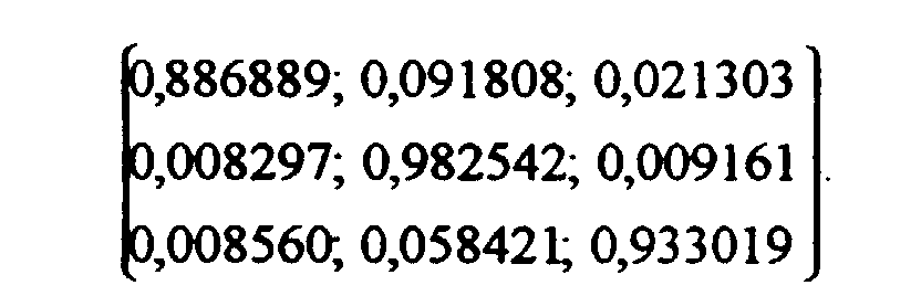
Die in der Tabelle angegebenen Koordinaten lassen sich mit einer Bilderzeugungseinrichtung verwirklichen, deren Laser als Lichtquellen zur Darstellung der Bildpunkte die Wellenlängen 647, Inm für rot, 514, 5 nm für Grün und 457, 9 nm für blau aufweisen.The coordinates given in the table can be marked with a Realize imaging device, its lasers as light sources for display the pixels have the wavelengths 647, Inm for red, 514, 5 nm for green and 457, 9 nm for blue.
Eine andere Umsetzung, die den Unbuntpunkt oder einen Weißton unberücksichtigt
läßt sich erzeugen, wenn man gemäß den Abbildungen in den Figuren 2 und 3 den
Ansatz macht:
Ein Ausführungsbeispiel gemäß diesem Ansatz wird im folgenden Anhand der Figuren 4 bis 6 beschrieben, wobei unter anderem dargestellt wird, wie bei einer erfindungsgemäßen Vorrichtung eine vom Benutzer einstellbare Sättigungserhöhung durchgeführt werden kann.An embodiment according to this approach is described below with reference to the figures 4 to 6, which is shown, among other things, as in a Device according to the invention a saturation increase adjustable by the user can be carried out.
Eine erhöhte Sättigung um den Faktor S tritt beispielsweise auf, wenn die fiktiven
Primärvalenzen gemäß dem angegebenen Ansatz als
Ein Farbvektor (F)=r(R)+g(G)+b(B) mit den Komponenten r, g, b wird beispielsweise
dann in ein fiktives Primärvalenzsystem (R'), (G'), (B') überführt, wenn die
Komponenten nach Umsetzung gleichbleiben, also für den Farbvektor für die
gesättigten Farben
Dann stellt sich der durch die Umsetzung gegebene Farbvektor gemäß der
angegebenen Wahl der fiktiven Primarvalenzen dar als
Wird der ebenfalls auf 1 normierte Weißton ebenfalls mit Komponenten LR, LG, LB im
eingangsseitigen Primärsystem als (w)=LR(R) + LG(G)+ LB(B) dargestellt wird, ergibt
sich für den durch Umsetzen erzeugten Farbvektor FUM im eingangsseitigen
Primärvalenzsystem (R), (G), (B) die Gleichung:
Man erkennt daraus, daß der durch die Umsetzung entstehende Farbvektor im eingangsseitigen Primärsystem für S>1 auch negative Komponenten aufweisen kann, was zeigt, daß die Umsetzung wie erwartet aus dem Farbvalenzbereich der eingangsseitigen Primärvalenzen (R), (G), (B) herauführen kann. Schaltungstechnisch bereiten negative Farbwertsignale weiter keine Probleme, da die noch folgende Transformation von den fiktiven Primärvalenzen auf die bildseitigen Primärvalenzen wieder einen größeren Farbvalenzbereich erzeugt, wodurch die dann erzeugten Farbwertsignale wieder auf positive und physikalisch sinnvolle Werte transformiert werden können.It can be seen from this that the color vector resulting from the implementation in primary system for S> 1 may also have negative components, which shows that the implementation as expected from the color valence range of the upstream primary valences (R), (G), (B). Circuitry Negative color value signals continue to cause no problems since the following Transformation from the fictitious primary valences to the image-side primary valences again creates a larger color valence range, which then creates the Color value signals are transformed back to positive and physically meaningful values can be.
Bei dem nachfolgenden Ausführungsbeispiel wird eine Schaltung 20 verwendet, mit
der die obige Gleichung für Farbwertsignale analog nachgebildet wird. Dabei wird aber
die Sättigung S als Gesamtverstärkung ausgeklammert:
In Fig. 4 ist die Schaltung 20 zum Umsetzen von Farbwertsignalen gemäß der
angegebenen Gleichung gezeigt. Sie enthält als wesentliche Bauelemente vier
Operationsverstärker 22, 24, 26 und 28. Signale mit den Farbwerten r, g, b werden an
die invertierenden Eingänge der Operationsverstärker 22, 24 und 26 über
Widerstände 30, 32 und 34 angelegt. Die Operationsverstärker 22, 24 und 26 sind mit
steuerbaren Widerständen 40, 42 und 44 gegengekoppelt. Die jeweiligen
Widerstandsverhältnisse der Widerstandswerte von den Widerständen 40, 42 und 44
und den Widerständen 30, 32 und 34 bestimmen den Verstärkungsfaktor durch die
Operationsverstärker 22, 24 und 26. Die Widerstände 30, 32, 34, 40, 42, 44 sind so
ausgelegt, daß sich entsprechend der externen Steuerung ein Verstärkungsfaktor S
gemäß der erwünschten Sättigung ergibt. Über Widerstände 46, 47, 48 und den
Operationsverstärker 28 wird von den Ausgangsspannungen der Operationsverstärker
22, 24, 26 aber eine Spannungswert abgezogen, der bei entsprechender
Dimensionierung dem Term [1 - 1/S] (r + g + b) (w) entspricht. Dabei dienen die
Widerstände 50, 52, 54 gleichen Werts zur Summierung der Farbwertsignale r, g und
b. Die Verstärkung des Verstärkers 28, der von dem Widerstandswert eines ersten
steuerbaren Widerstandes 56 abhängt, wird auf (1 - 1/S) ausgelegt. Die Widerstände
46, 47, 48 dienen zur Bedämpfung entsprechend den Komponenten LR, LG und LB
des Farbvektors (w).4 shows the
Die Verstärkungen der Operationsverstärker 22, 24, 26 und 28 und hier über Gegenkopplungswiderstände
40, 42, 44, 56 steuerbar. Man könnte statt dieser aber auch
Verstärker einsetzen, deren Verstärkung über eine Spannung einstellbar ist.
Allerdings sind diese bei den benötigten hohen Frequenzen in einem Videosystem
sehr aufwendig. Deshalb wird hier eine Standardschaltung über Operationsverstärker
und steuerbare Widerstände vorgezogen. Steuerbare Widerstände können,
beispielsweise über ein Magnetfeld oder über eine Heizung eingestellt werden. Man
kann jedoch die Verstärkungen auch digital steuern, wenn für die Widerstände 40, 42,
44, 56 jeweils eine Schaltung gemäß Fig. 5 eingesetzt wird. Das Beispiel von Fig. 5
ist auf 16 Stufen von Widerstandswerten entsprechend einer 4 Bitdarstellung für s
ausgelegt. Der steuerbare Widerstand gemäß Fig. 5 ist durch in Reihe geschaltete
Widerstände 60, 62, 64, 66 und 68 ausgebildet, wobei die Widerstände 62, 64, 66
und 68 über die Drain-Source-Strecke von Feldeffekttransistoren 70, 72, 74, 76
kurzschließbar sind. Solche Feldeffekttransistoren sind als Analogschalter von der
Firma Texas Instruments zusammen mit Ansteuerelektronik als integrierte
Schaltungen unter der Bezeichnung TL 182C, TL 185C, TL 188C oder TL 191 C
erhältlich, bei denen aber bei der Berechnung der Widerstände 62, 64, 66 und 68 der
recht hohe Widerstand der Drain-Source-Strecke von über 100Ω berücksichtigt
werden muß. Man kann solche Schaltungen jedoch auch konventionell aufbauen,
weshalb im folgenden angenommen wird, daß die Drain-Source-Strecke im
Kurzschlußfall einen Widerstand von Null hat und der Widerstandswert im gesperrten
Fall wesentlich größer als der Widerstand 60 ist. Dann muß für eine binäre
Ansteuerung, wie sie in der Zeichnung durch die mit 20, 21, 22, 23 für den jeweiligen
Wert einer binären Stelle eines Binärwerts bezeichneten Eingänge dargestellt ist, der
Widerstand 64 doppelt so groß wie der Widerstand 62, der Widerstand 66 doppelt so
groß wie der Widerstand 64 und der Widerstand 68 doppelt so groß wie der
Widerstand 66 sein. Wenn man beispielsweise Sättigungserhöhungen von 10%
erreichen will, ist für die Summe der Widerstandswerte der Widerstände von 62, 64,
66 und 68 10% des Wertes des Widerstandes 60 zu wählen.The gains of the
Bei derartig kleinen Sättigungserhöhungen läßt sich wegen 1 - 1/S , S - 1 auch der
Faktor (1 - 1/S) für den Operationsverstärker 28 leicht digital steuern, indem man
nämlich den Widerstand 60 bei der Nachbildung des Widerstandes 56 aufgrund der
Schaltung von Fig. 5 wegläßt (Widerstandswert 0 Ω, für Widerstand 60), ferner
dieselben Werte der Widerstände 62, 64, 66, 68 wie bei den steuerbaren
Widerständen 40, 42, 44 vorsieht und die Werte der Widerstände 30, 32, 34, 50, 52,
54 in Fig. 4 gleich wählt.With such small increases in saturation, because of 1 - 1 / S, S - 1 the
Easily digitally control factor (1 - 1 / S) for
Eine solche Beschaltung gemäß Fig. 4 und 5 gestattet eine Erhöhung der Sättigung in 16 Stufen, wobei die Stufen durch einen digital dargestellten Binärwert geschaltet werden. Dieser kann beispielsweise aus dem Spannungsabfall am Abgriff eines Potentiometers über einen Analog-Digitalwandler gewonnen werden. Die Erweiterung solcher Schaltungen auf mehr als 16 Stufen läßt sich durch entsprechende Beschaltung mit mehr Feldeffekttransistoren und Widerstände in gleicher Weise erzielen.Such a connection according to FIGS. 4 and 5 permits an increase in the saturation in 16 stages, the stages switched by a digitally represented binary value become. This can, for example, from the voltage drop at the tap Potentiometers can be obtained via an analog-digital converter. The Such circuits can be expanded to more than 16 stages appropriate wiring with more field effect transistors and resistors in achieve the same way.
In Fig. 6 ist gezeigt, wie die Schaltung 20 gemäß Fig. 4 in einen Matrixschaltkreis 14
eingefügt werden kann. Die Signale für die Farbwerte r, g, b liegen an den Eingängen
der Schaltung 20 an, deren Faktor S für die Erhöhung der Sättigung an den mit 20,
21, 22, 23 bezeichneten Eingängen als Binärwert über Logiksignale bestimmt ist. Die
gemäß der angegebene Gleichung durch den Schaltkreis 20 umgesetzten Signale
werden anschließend auf einen Matrixschaltkreis 80 gegeben, der nach dem Stand der
Technik so aufgebaut ist, daß von Farbwertsignalen der eingangsseitigen
Primärvalenzen (R, G, B) auf Farbwertsignale der bildseitigen Primärvalenzen (R",
G", B") zur Farbdarstellung in der Bilderzeugungseinrichtung 12 transformiert wird.
Außerdem wird im Matrixschaltkreis 80 die Vorzeichenumkehr der Farbwertsignale
für die Farbwerte r, g, b durch den Schaltkreis 20 berücksichtigt. An jedem Ausgang
des Matrixschaltkreises 80 ist je ein Unterdrückungsschaltkreis aus je einem
Widerstand 82, 84, 86 und einer Diode 92, 94, 96 bestehenden Spannungsteiler
vorgesehen. Diese Unterdrückungsschaltkreise unterdrücken Spannungen falscher
Polarität, die dann entstehen, wenn die Erhöhung der Sättigung aus dem
Farbtonbereich des durch die Primärvalenzen (R", G", B") aufgespannten
Farbtonbereich hinausführt Dies könnte beispielsweise bei einem sehr großen S
möglich werden, wie man aus der Fig. 2 an der blauen Primärvalenz sieht, für die
aufgrund des begrenzten Farbvalenzbereichs nur eine geringe Sättigungserhöhung
möglich ist.FIG. 6 shows how the
Die Dioden 92, 94, 96 sind hier gegen ein Gegenpotential von 0, 7 Volt geschaltet,
das die Schwellspannung von den im Ausführungsbeispiel verwendeten
Siliziumdioden 92, 94, 96 ist. Die dargestellte Ansteuerung der Dioden 92, 94, 96
sorgt dafür, daß die Ausgangssignale des Matrixschaltkreises 14 bei negativen
Ausgangssignalen des Matrixschaltkreises 80 logarithmisch asymptotisch zu Null
gehen. Der Einsatz des logarithmischen Verhaltens wird durch die Auslegung der
Widerstände 82, 84 und 86 in Verbindung mit den Diodenkennlinien der Dioden 92,
94 und 96 in bekannter Weise bestimmt.The
Das Verfahren und das Farbvideosystem wurden vorhergehend für drei bildseitige Primärvalenzen dargestellt. Es ist natürlich auch möglich, mehr als drei bildseitige Primärvalenzen zu verwenden, die mit einer entsprechenden Matrix angesteuert werden. Dann ergibt sich ein noch größerer Bereich für Farbtonänderungen und Sättigungserhöhungen, die nach dem gleichen Verfahren durchgeführt werden können.The method and color video system were previously for three image-side Primary valences shown. It is of course also possible to have more than three images To use primary valences, which are controlled with a corresponding matrix become. Then there is an even larger area for color changes and Saturation increases, which are carried out according to the same procedure can.
Claims (12)
- Method for colour transformation of the colour valences of pixels of a colour video system, in which each colour valence can be represented by components of a colour vector within a colour-valence range which includes an achromatic point (w) and is set by input primary valences (R, G, B) from a signal source, and in which picture primary valences (R", G", B") whose colour-valence range also includes the achromatic point (w) are used for representing the pixels, at least one colour valence in this colour-valence range lying outside the colour-valence range of the input primary valences (R, G, B) and a transformation being carried out to produce components related to picture primary valences (R", G", B") and picture components with negative intensity being suppressed if they occur, characterized in that fictitious primary valences (R', G', B') are established whose colour-valence range contains the at least one colour valence outside the colour-valence range of the input primary valences and within the colour-valence range of the picture primary valences (R", G", B"), and the transformation is carried out by:converting the components of the colour vector from the input primary valences to the fictitious primary valences (R', G', B') in such a way that the colour valence of at least one input primary valence (R, G, B) is shifted to the at least one colour valence outside the colour-valence range of the input primary valences, andtransforming the converted components of the colour vector from the fictitious primary valences (R', G', B') to the picture primary valences (R", G", B") to produce picture components of a colour vector, the picture colour valences produced in this way having the same hue and the same saturation as the transformed colour valence in the fictitious primary-valence system (R', G', B').
- Method according to Claim 1, characterized in that the colour valence of the achromatic point (w) remains unchanged by the conversion into components of a colour vector in the fictitious primary-valence system (R', G', B').
- Method according to Claim 1 or 2, characterized in that the conversion of the components of the colour vector from the input primary-valence system to the fictitious primary system (R', G', B') is carried out by means of a matrix transformation of the components of the colour vector.
- Method according to Claim 3, characterized in that a single matrix transformation is carried out with a matrix which is given by the product of the conversion matrix multiplied by a matrix for transformation from the fictitious primary-valence system (R', G', B') to the picture primary-valence system (R", G", B").
- Method according to Claim 1 to 4, characterized in that the fictitious primary valences (R', G', B') are set to colour valences which have the same hue as the input primary valences (R, G, B) but an increased saturation for at least one of the input primary valences (R, G, B).
- Colour video system for representing coloured pixels, having an input circuit (10) for producing or receiving colour-value signals associated with input primary valences (R, G, B) for a colour-valence range which contains an achromatic point (w), having a picture-production device (12) for producing the pixels of a colour video picture on the basis of picture primary valences (R", G", B") whose colour-valence range contains the achromatic point (w) and at least one colour valence outside the colour-valence range of the input primary valences (R, G, B), and having a matrix circuit (14) which is connected between the input circuit (10) and the picture-production device (12), characterized in that a circuit (15) is provided for converting colour-value signals related to the input primary valences to colour-value signals related to fictitious primary valences (R', G', B') whose colour-valence range contains the at least one colour valence outside the colour-valence range of the input primary valences and within the colour-valence range of the picture primary valences (R", G", B"), it being possible for the colour-value signals of at least one input primary valence (R, G, B) to be converted to colour-value signals for the at least one colour valence outside the colour-valence range of the input primary valences (R", G", B") by means of the circuit (15), and the matrix circuit (14) being designed to transform the colour-value signals related to the fictitious primary valences (R', G', B') to the picture primary valences (R", G", B").
- Colour video system according to Claim 6, characterized in that the circuit (10) for converting the input colour-value signals to the fictitious primary valences (R', G', B') is designed in such a way that the colour valence of the achromatic point (w) can be represented in the picture with the input colour valence.
- Colour video system according to Claim 6 or 7, characterized in that the conversion circuit (15) contains a further matrix circuit for a further matrix transformation.
- Colour video system according to Claim 8, characterized in that the matrix circuit (14) contains the conversion circuit (15) by being designed for a matrix transformation with a single transformation matrix which is the product of the matrix for the matrix transformation of the conversion and the matrix for the transformation of the colour-value signals from the fictitious primary-valence system (R', G', B') to the picture primary valences (R", G", B").
- Colour video system according to at least one of Claims 6 to 10, characterized in that the conversion circuit (15) can be driven for differently selectable fictitious primary valences (R', G', B').
- Colour video system according to Claim 10, characterized in that the circuit (15) for differently selectable fictitious primary valences has controllable resistors which can be varied by control voltages which can be applied to, or currents which can be introduced in, the circuit.
- Colour video system according to at least one of Claims 6 to 11, characterized in that suppression circuits for negative picture colour-value signals are provided, which have one voltage divider, made up of a diode (92, 94, 96) and a resistor (82, 84, 86), for each colour-value signal, the voltage dividers being connected at the diodes to a potential compensating for the threshold voltages of the diodes (92, 94, 96).
Applications Claiming Priority (3)
| Application Number | Priority Date | Filing Date | Title |
|---|---|---|---|
| DE19506595 | 1995-02-24 | ||
| DE19506595A DE19506595C1 (en) | 1995-02-24 | 1995-02-24 | Transformation of colour signals in colour video system |
| PCT/EP1996/000378 WO1996026613A1 (en) | 1995-02-24 | 1996-01-30 | Colour transformation process and a colour video system |
Publications (2)
| Publication Number | Publication Date |
|---|---|
| EP0758514A1 EP0758514A1 (en) | 1997-02-19 |
| EP0758514B1 true EP0758514B1 (en) | 1999-05-12 |
Family
ID=7755014
Family Applications (1)
| Application Number | Title | Priority Date | Filing Date |
|---|---|---|---|
| EP96902260A Expired - Lifetime EP0758514B1 (en) | 1995-02-24 | 1996-01-30 | Colour transformation process and a colour video system |
Country Status (10)
| Country | Link |
|---|---|
| US (1) | US6025885A (en) |
| EP (1) | EP0758514B1 (en) |
| JP (1) | JP3107396B2 (en) |
| KR (1) | KR100211683B1 (en) |
| CN (1) | CN1092005C (en) |
| AT (1) | ATE180132T1 (en) |
| BR (1) | BR9606235A (en) |
| DE (2) | DE19506595C1 (en) |
| FI (1) | FI964234A (en) |
| WO (1) | WO1996026613A1 (en) |
Cited By (1)
| Publication number | Priority date | Publication date | Assignee | Title |
|---|---|---|---|---|
| US6865287B1 (en) | 1999-09-09 | 2005-03-08 | Heimann Systems Gmbh | Method for adjusting color in an image |
Families Citing this family (23)
| Publication number | Priority date | Publication date | Assignee | Title |
|---|---|---|---|---|
| FI950745A (en) | 1995-02-17 | 1996-08-18 | Nokia Telecommunications Oy | Picking up mobile stations from a direct channel |
| US6154259A (en) * | 1996-11-27 | 2000-11-28 | Photera Technologies, Inc. | Multi-beam laser scanning display system with speckle elimination |
| WO1998026328A2 (en) | 1996-11-29 | 1998-06-18 | Corporation For Laser Optics Research | Monochromatic r,g,b laser light source display system and method |
| US7382379B1 (en) * | 1997-06-27 | 2008-06-03 | Eastman Kodak Company | Arrangement for mapping colors between imaging systems and method thereof |
| US6320592B1 (en) * | 1997-06-30 | 2001-11-20 | Sun Microsystems, Inc. | Method and apparatus for separating image data from a color system in image processing |
| US6362808B1 (en) * | 1997-07-03 | 2002-03-26 | Minnesota Mining And Manufacturing Company | Arrangement for mapping colors between imaging systems and method therefor |
| JP3607059B2 (en) * | 1997-09-19 | 2005-01-05 | コニカミノルタビジネステクノロジーズ株式会社 | Color feature extraction apparatus, color feature extraction method, and program storage medium |
| NL1007531C2 (en) * | 1997-11-12 | 1999-06-02 | Tno | Method and device for displaying a color image. |
| JP4257033B2 (en) * | 1998-08-14 | 2009-04-22 | コーニンクレッカ フィリップス エレクトロニクス エヌ ヴィ | Color signal matrix adjustment |
| JP3702699B2 (en) * | 1999-03-26 | 2005-10-05 | 三菱電機株式会社 | Color image display device |
| US7158670B1 (en) * | 1999-05-21 | 2007-01-02 | Microsoft Corporation | Visually error-free color image representation |
| US6268847B1 (en) * | 1999-06-02 | 2001-07-31 | Ati International Srl | Method and apparatus for more accurate color base conversion of YUV video data |
| US6750874B1 (en) | 1999-11-06 | 2004-06-15 | Samsung Electronics Co., Ltd. | Display device using single liquid crystal display panel |
| US7042521B2 (en) * | 2002-08-29 | 2006-05-09 | Samsung Electronics Co., Ltd. | Method for color saturation adjustment in an RGB color system |
| US6956581B2 (en) * | 2002-09-19 | 2005-10-18 | Lexmark International, Inc. | Gamut mapping algorithm for business graphics |
| JP2004112694A (en) * | 2002-09-20 | 2004-04-08 | Fuji Xerox Co Ltd | Color control method, color control apparatus, color conversion definition editing apparatus, image processing apparatus, program, and storage medium |
| KR20040107614A (en) * | 2003-06-05 | 2004-12-23 | 삼성전자주식회사 | Color signal processing apparatus for color reproduction on MPD and method of using the same |
| FR2857814A1 (en) * | 2003-07-17 | 2005-01-21 | Thomson Licensing Sa | Color images display device for projector, has colored rotating wheels generating colored beam with base colors in synchronization with images generated by imager, where wheels position is adjusted to modify shades of colors |
| EP1742458A1 (en) | 2005-06-13 | 2007-01-10 | Thomson Licensing | Apparatus and method for image processing of digital image pixels |
| US7408558B2 (en) | 2005-08-25 | 2008-08-05 | Eastman Kodak Company | Laser-based display having expanded image color |
| US7489437B1 (en) | 2007-12-05 | 2009-02-10 | Corning Incorporated | Fiber laser red-green-blue (RGB) light source |
| US8629884B2 (en) * | 2007-12-07 | 2014-01-14 | Ati Technologies Ulc | Wide color gamut display system |
| DE102008017072A1 (en) * | 2008-04-03 | 2009-10-08 | Ledon Lighting Gmbh | Implementation of color information for the control of a light source |
Family Cites Families (15)
| Publication number | Priority date | Publication date | Assignee | Title |
|---|---|---|---|---|
| DE2318804A1 (en) * | 1973-04-13 | 1974-10-24 | Patra Patent Treuhand | TRANSMISSION DEVICE OF A COLOR TELEVISION RECORDING AND PLAYBACK DEVICE |
| DE2607623B2 (en) * | 1976-02-25 | 1978-12-21 | Dr.-Ing. Rudolf Hell Gmbh, 2300 Kiel | Color evaluation device |
| DE2719387C3 (en) * | 1977-04-30 | 1980-12-04 | Dr.-Ing. Rudolf Hell Gmbh, 2300 Kiel | Device for displaying overcorrections in electronic color correction |
| DE2844158C3 (en) * | 1978-10-10 | 1981-10-15 | Burda Verwaltungs Kg Schutterwald, 7600 Offenburg | Process for the reproduction of original documents which are scanned for their color content according to a three-range process |
| DE3315616A1 (en) * | 1983-04-29 | 1984-10-31 | Agfa-Gevaert Ag, 5090 Leverkusen | METHOD FOR SETTING THE COLOR SATURATION OF COLOR SIGNALS |
| JPH0657066B2 (en) * | 1984-12-20 | 1994-07-27 | キヤノン株式会社 | Color adjustment device |
| DE3629469C2 (en) * | 1986-08-29 | 1994-10-06 | Agfa Gevaert Ag | Process for adjusting the color saturation in electronic image processing |
| US5239370A (en) * | 1990-04-24 | 1993-08-24 | Brother Kogyo Kabushiki Kaisha | Color image forming apparatus having color-correcting unit operating in accordance with a gamut of an image input medium |
| US5418575A (en) * | 1991-12-11 | 1995-05-23 | Hitachi, Ltd. | Color display apparatus having compensating unit |
| JPH0670148A (en) * | 1992-08-20 | 1994-03-11 | Fuji Xerox Co Ltd | Color converting method/device |
| KR0165279B1 (en) * | 1992-11-27 | 1999-03-20 | 김광호 | Equipment processing colour signal with low frequency conversion |
| DE4306797C1 (en) * | 1993-03-04 | 1994-05-05 | Schneider Rundfunkwerke Ag | Generating colour pixels of TV image - providing projection system using coloured lasers supplied with colour tone signals converted from phosphor screen base system to laser projection base system |
| JP3161172B2 (en) * | 1993-08-06 | 2001-04-25 | ミノルタ株式会社 | Encoding device |
| US5450217A (en) * | 1994-05-23 | 1995-09-12 | Xerox Corporation | Image-dependent color saturation correction in a natural scene pictorial image |
| US5517335A (en) * | 1994-10-11 | 1996-05-14 | Seiko Epson Corporation | Apparatus and method for enhancing color saturation in halftoned images |
-
1995
- 1995-02-24 DE DE19506595A patent/DE19506595C1/en not_active Expired - Fee Related
-
1996
- 1996-01-30 EP EP96902260A patent/EP0758514B1/en not_active Expired - Lifetime
- 1996-01-30 KR KR1019960705913A patent/KR100211683B1/en not_active IP Right Cessation
- 1996-01-30 BR BR9606235A patent/BR9606235A/en not_active IP Right Cessation
- 1996-01-30 DE DE59601860T patent/DE59601860D1/en not_active Expired - Lifetime
- 1996-01-30 AT AT96902260T patent/ATE180132T1/en not_active IP Right Cessation
- 1996-01-30 WO PCT/EP1996/000378 patent/WO1996026613A1/en active IP Right Grant
- 1996-01-30 CN CN96190124A patent/CN1092005C/en not_active Expired - Fee Related
- 1996-01-30 JP JP08525335A patent/JP3107396B2/en not_active Expired - Fee Related
- 1996-01-30 US US08/718,358 patent/US6025885A/en not_active Expired - Lifetime
- 1996-10-21 FI FI964234A patent/FI964234A/en unknown
Cited By (1)
| Publication number | Priority date | Publication date | Assignee | Title |
|---|---|---|---|---|
| US6865287B1 (en) | 1999-09-09 | 2005-03-08 | Heimann Systems Gmbh | Method for adjusting color in an image |
Also Published As
| Publication number | Publication date |
|---|---|
| ATE180132T1 (en) | 1999-05-15 |
| FI964234A (en) | 1996-12-13 |
| US6025885A (en) | 2000-02-15 |
| EP0758514A1 (en) | 1997-02-19 |
| WO1996026613A1 (en) | 1996-08-29 |
| BR9606235A (en) | 1997-09-02 |
| DE59601860D1 (en) | 1999-06-17 |
| KR100211683B1 (en) | 1999-08-02 |
| CN1146842A (en) | 1997-04-02 |
| JPH09512414A (en) | 1997-12-09 |
| JP3107396B2 (en) | 2000-11-06 |
| FI964234A0 (en) | 1996-10-21 |
| KR970702669A (en) | 1997-05-13 |
| DE19506595C1 (en) | 1996-02-01 |
| CN1092005C (en) | 2002-10-02 |
Similar Documents
| Publication | Publication Date | Title |
|---|---|---|
| EP0758514B1 (en) | Colour transformation process and a colour video system | |
| DE2932525C2 (en) | ||
| DE3437748A1 (en) | IMAGE SIGNAL PROCESSING DEVICE | |
| DE2207536B2 (en) | Contrast compression circuit for a color television pickup system having a plurality of image pickup tubes | |
| DE2613841B2 (en) | Signal mixer for television purposes | |
| DE2905350C3 (en) | Converter and monochrome picture display device with such a converter | |
| DE2913404A1 (en) | DIGITAL CIRCUIT ARRANGEMENT FOR CREATING A DISPLAY EFFECT IN THE REPRODUCTION OF A VIDEO SIGNAL | |
| DE1916690A1 (en) | Color coding matrix | |
| EP0614319B1 (en) | Television projection system | |
| DE3238696A1 (en) | COLOR KEY SIGNAL GENERATOR | |
| DE938699C (en) | Method for reproducing colored images | |
| EP0107072A2 (en) | Method of colour space encoding digital colour video signals, and system using such a method | |
| EP0135599B1 (en) | Digital filter integrated circuit for the luminance channel of a colour television receiver | |
| EP0019735B1 (en) | Method and circuit for contrast correction of colour television signals | |
| DE3419645A1 (en) | TRANSVERSAL FILTER WITH MOS TRANSISTOR AMPLIFIERS | |
| DE10061451B4 (en) | Device for processing R, G, B signals in a digitally controlled display | |
| DE10055837A1 (en) | Method for capturing image information | |
| DE19833239A1 (en) | Video signal processing circuit | |
| DE2331216C3 (en) | Circuit arrangement for generating control signals for automatic color matching between three color signals | |
| DE2655219A1 (en) | Colour processing circuit in PAL TV receiver - feeds signals through two channels with delay in one equal to scan period | |
| DE2013219C3 (en) | Circuit arrangement for correcting the video signals supplied by a television camera with a gamma correction circuit | |
| DE19549658B4 (en) | Prim. colour signal display device using video data compression - performs subtraction of threshold from each prim. signal for adaptation of contrast level using complements of resulting differential values | |
| DE2111364C3 (en) | Trick control circuit for color and black and white signals | |
| DE2420670A1 (en) | Linear coding method for colour information - reduces irrelevance during colour coding in colour TV transmission system | |
| EP0323851A2 (en) | Method and apparatus for entering symbols into a programme televion signal |
Legal Events
| Date | Code | Title | Description |
|---|---|---|---|
| PUAI | Public reference made under article 153(3) epc to a published international application that has entered the european phase |
Free format text: ORIGINAL CODE: 0009012 |
|
| 17P | Request for examination filed |
Effective date: 19960826 |
|
| AK | Designated contracting states |
Kind code of ref document: A1 Designated state(s): AT BE CH DE DK ES FR GB GR IE IT LI LU NL PT SE |
|
| GRAG | Despatch of communication of intention to grant |
Free format text: ORIGINAL CODE: EPIDOS AGRA |
|
| GRAG | Despatch of communication of intention to grant |
Free format text: ORIGINAL CODE: EPIDOS AGRA |
|
| GRAH | Despatch of communication of intention to grant a patent |
Free format text: ORIGINAL CODE: EPIDOS IGRA |
|
| 17Q | First examination report despatched |
Effective date: 19981029 |
|
| GRAH | Despatch of communication of intention to grant a patent |
Free format text: ORIGINAL CODE: EPIDOS IGRA |
|
| GRAA | (expected) grant |
Free format text: ORIGINAL CODE: 0009210 |
|
| AK | Designated contracting states |
Kind code of ref document: B1 Designated state(s): AT BE CH DE DK ES FR GB GR IE IT LI LU NL PT SE |
|
| PG25 | Lapsed in a contracting state [announced via postgrant information from national office to epo] |
Ref country code: SE Free format text: THE PATENT HAS BEEN ANNULLED BY A DECISION OF A NATIONAL AUTHORITY Effective date: 19990512 Ref country code: IT Free format text: LAPSE BECAUSE OF FAILURE TO SUBMIT A TRANSLATION OF THE DESCRIPTION OR TO PAY THE FEE WITHIN THE PRE;WARNING: LAPSES OF ITALIAN PATENTS WITH EFFECTIVE DATE BEFORE 2007 MAY HAVE OCCURRED AT ANY TIME BEFORE 2007. THE CORRECT EFFECTIVE DATE MAY BE DIFFERENT FROM THE ONE RECORDED.SCRIBED TIME-LIMIT Effective date: 19990512 Ref country code: GR Free format text: LAPSE BECAUSE OF NON-PAYMENT OF DUE FEES Effective date: 19990512 Ref country code: ES Free format text: THE PATENT HAS BEEN ANNULLED BY A DECISION OF A NATIONAL AUTHORITY Effective date: 19990512 |
|
| REF | Corresponds to: |
Ref document number: 180132 Country of ref document: AT Date of ref document: 19990515 Kind code of ref document: T |
|
| REG | Reference to a national code |
Ref country code: CH Ref legal event code: EP |
|
| GBT | Gb: translation of ep patent filed (gb section 77(6)(a)/1977) |
Effective date: 19990521 |
|
| REG | Reference to a national code |
Ref country code: IE Ref legal event code: FG4D Free format text: GERMAN |
|
| REF | Corresponds to: |
Ref document number: 59601860 Country of ref document: DE Date of ref document: 19990617 |
|
| ET | Fr: translation filed | ||
| PG25 | Lapsed in a contracting state [announced via postgrant information from national office to epo] |
Ref country code: PT Free format text: LAPSE BECAUSE OF FAILURE TO SUBMIT A TRANSLATION OF THE DESCRIPTION OR TO PAY THE FEE WITHIN THE PRESCRIBED TIME-LIMIT Effective date: 19990812 Ref country code: DK Free format text: LAPSE BECAUSE OF FAILURE TO SUBMIT A TRANSLATION OF THE DESCRIPTION OR TO PAY THE FEE WITHIN THE PRESCRIBED TIME-LIMIT Effective date: 19990812 |
|
| PG25 | Lapsed in a contracting state [announced via postgrant information from national office to epo] |
Ref country code: LU Free format text: LAPSE BECAUSE OF NON-PAYMENT OF DUE FEES Effective date: 20000130 Ref country code: AT Free format text: LAPSE BECAUSE OF NON-PAYMENT OF DUE FEES Effective date: 20000130 |
|
| PG25 | Lapsed in a contracting state [announced via postgrant information from national office to epo] |
Ref country code: LI Free format text: LAPSE BECAUSE OF NON-PAYMENT OF DUE FEES Effective date: 20000131 Ref country code: CH Free format text: LAPSE BECAUSE OF NON-PAYMENT OF DUE FEES Effective date: 20000131 Ref country code: BE Free format text: LAPSE BECAUSE OF NON-PAYMENT OF DUE FEES Effective date: 20000131 |
|
| PLBE | No opposition filed within time limit |
Free format text: ORIGINAL CODE: 0009261 |
|
| STAA | Information on the status of an ep patent application or granted ep patent |
Free format text: STATUS: NO OPPOSITION FILED WITHIN TIME LIMIT |
|
| 26N | No opposition filed | ||
| PG25 | Lapsed in a contracting state [announced via postgrant information from national office to epo] |
Ref country code: IE Free format text: LAPSE BECAUSE OF NON-PAYMENT OF DUE FEES Effective date: 20000719 |
|
| BERE | Be: lapsed |
Owner name: LDT G.M.B.H. & CO. LASER-DISPLAY-TECHNOLOGIE K.G. Effective date: 20000131 |
|
| REG | Reference to a national code |
Ref country code: IE Ref legal event code: FD4D |
|
| REG | Reference to a national code |
Ref country code: CH Ref legal event code: PL |
|
| REG | Reference to a national code |
Ref country code: GB Ref legal event code: IF02 |
|
| PGFP | Annual fee paid to national office [announced via postgrant information from national office to epo] |
Ref country code: NL Payment date: 20020131 Year of fee payment: 7 |
|
| PG25 | Lapsed in a contracting state [announced via postgrant information from national office to epo] |
Ref country code: NL Free format text: LAPSE BECAUSE OF NON-PAYMENT OF DUE FEES Effective date: 20030801 |
|
| NLV4 | Nl: lapsed or anulled due to non-payment of the annual fee |
Effective date: 20030801 |
|
| PGFP | Annual fee paid to national office [announced via postgrant information from national office to epo] |
Ref country code: FR Payment date: 20130213 Year of fee payment: 18 Ref country code: DE Payment date: 20130122 Year of fee payment: 18 Ref country code: GB Payment date: 20130122 Year of fee payment: 18 |
|
| REG | Reference to a national code |
Ref country code: DE Ref legal event code: R119 Ref document number: 59601860 Country of ref document: DE |
|
| GBPC | Gb: european patent ceased through non-payment of renewal fee |
Effective date: 20140130 |
|
| REG | Reference to a national code |
Ref country code: DE Ref legal event code: R119 Ref document number: 59601860 Country of ref document: DE Effective date: 20140801 |
|
| PG25 | Lapsed in a contracting state [announced via postgrant information from national office to epo] |
Ref country code: DE Free format text: LAPSE BECAUSE OF NON-PAYMENT OF DUE FEES Effective date: 20140801 |
|
| REG | Reference to a national code |
Ref country code: FR Ref legal event code: ST Effective date: 20140930 |
|
| PG25 | Lapsed in a contracting state [announced via postgrant information from national office to epo] |
Ref country code: FR Free format text: LAPSE BECAUSE OF NON-PAYMENT OF DUE FEES Effective date: 20140131 Ref country code: GB Free format text: LAPSE BECAUSE OF NON-PAYMENT OF DUE FEES Effective date: 20140130 |