EP0758043A1 - Concrete form deformation preventing member and method of assembling concrete form with the same - Google Patents
Concrete form deformation preventing member and method of assembling concrete form with the same Download PDFInfo
- Publication number
- EP0758043A1 EP0758043A1 EP96111090A EP96111090A EP0758043A1 EP 0758043 A1 EP0758043 A1 EP 0758043A1 EP 96111090 A EP96111090 A EP 96111090A EP 96111090 A EP96111090 A EP 96111090A EP 0758043 A1 EP0758043 A1 EP 0758043A1
- Authority
- EP
- European Patent Office
- Prior art keywords
- concrete form
- plate portion
- main plate
- preventing member
- deformation preventing
- Prior art date
- Legal status (The legal status is an assumption and is not a legal conclusion. Google has not performed a legal analysis and makes no representation as to the accuracy of the status listed.)
- Ceased
Links
Images


Classifications
-
- E—FIXED CONSTRUCTIONS
- E04—BUILDING
- E04G—SCAFFOLDING; FORMS; SHUTTERING; BUILDING IMPLEMENTS OR AIDS, OR THEIR USE; HANDLING BUILDING MATERIALS ON THE SITE; REPAIRING, BREAKING-UP OR OTHER WORK ON EXISTING BUILDINGS
- E04G11/00—Forms, shutterings, or falsework for making walls, floors, ceilings, or roofs
- E04G11/06—Forms, shutterings, or falsework for making walls, floors, ceilings, or roofs for walls, e.g. curved end panels for wall shutterings; filler elements for wall shutterings; shutterings for vertical ducts
- E04G11/08—Forms, which are completely dismantled after setting of the concrete and re-built for next pouring
- E04G11/12—Forms, which are completely dismantled after setting of the concrete and re-built for next pouring of elements and beams which are mounted during erection of the shuttering to brace or couple the elements
-
- E—FIXED CONSTRUCTIONS
- E04—BUILDING
- E04G—SCAFFOLDING; FORMS; SHUTTERING; BUILDING IMPLEMENTS OR AIDS, OR THEIR USE; HANDLING BUILDING MATERIALS ON THE SITE; REPAIRING, BREAKING-UP OR OTHER WORK ON EXISTING BUILDINGS
- E04G17/00—Connecting or other auxiliary members for forms, falsework structures, or shutterings
- E04G17/06—Tying means; Spacers ; Devices for extracting or inserting wall ties
-
- E—FIXED CONSTRUCTIONS
- E04—BUILDING
- E04G—SCAFFOLDING; FORMS; SHUTTERING; BUILDING IMPLEMENTS OR AIDS, OR THEIR USE; HANDLING BUILDING MATERIALS ON THE SITE; REPAIRING, BREAKING-UP OR OTHER WORK ON EXISTING BUILDINGS
- E04G17/00—Connecting or other auxiliary members for forms, falsework structures, or shutterings
- E04G17/14—Bracing or strutting arrangements for formwalls; Devices for aligning forms
Definitions
- the present invention relates to a concrete form deformation preventing member for preventing deformation of a form panel which is employed for concrete placing or molding of concrete secondary products in construction or civil engineering works, for example, in assembling of a concrete form, and a method of assembling a concrete form with the same.
- a wood form panel prepared by nailing crossbars to a plywood board and a metal form panel prepared by fixing metal ribs to an iron plate or an aluminum plate are known as such form panels.
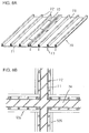
- Fig. 8A shows form panels 70, each of which is prepared by fastening and fixing a flat plate 71 consisting of plywood to a plurality of reinforcing crossbars 72 with nails 73.
- the reinforcing crossbars 72 of the adjacent form panels 70 are fastened to each other with nails 73, thereby mutually coupling/fixing the form panels 70 with/to each other.
- Fig. 8B shows an exemplary concrete form having a cross concrete form portion 74, which is assembled in the aforementioned manner.
- the flat plates 71 may be prepared from plastic plates, in place of plywood boards.
- each separator 121 has a pair of male screws 121a which are formed on both ends of a bar.
- Each male screw 121a fits with a female screw 122c which is provided on one end of each attachment 122 shown in Fig. 11B.
- a male screw 122d which is formed on the other end of the attachment 122 to be substantially coaxial with the female screw 122c passes through a spacing fixture mounting hole 76 provided in each form panel 70, so that an end of a substantially truncated-conical presser part 122a of resin which is engaged with the outer periphery of an attachment body part 122b comes into contact with a concrete placing surface of the form panel 70.
- a male screw 123b is provided on the other end of the clamping member 123, so that a pair of thin angular cylindrical form support members 126 of a metal are opposed to each other through each clamping member 123 by a support member 124 and a nut 125 which are mounted on the male screw 123b, thereby bridging a plurality of transversely arranged form panels 70 with each other.
- each form panel is prepared by mounting vertical reinforcements 72 on a plywood board 71 having a width W of 900 mm at pitches (lengths P shown in Fig. 12) of about 300 mm, for example, as shown in Fig. 12. Therefore, spacing fixture mounting holes 76 and the vertical reinforcements 72 are at relatively large distances, and hence such plywood boards 71, which must be in a state shown in Fig. 10A, are deformed as shown in Fig. 10B, due to dispersion in clamping strength of the nuts 125 against the male screws 123b of the clamping members 123.
- a pair of round pipes 127 may be interposed between each plywood board 71 and each thin angular cylindrical form support member 126 around both sides of each spacing fixture mounting hole 76 as shown in Fig. 13, for example.
- deformation of the plywood board 71 caused by clamping is suppressed to some extent.
- the round pipes 127 are in line contact with the surface of the plywood board 71, and hence the space between the contact lines of the pair of round pipes 127 with the plywood board 71 is increased.
- the effect for suppressing deformation of the plywood board 71 is insufficient.
- a pair of thin angular cylindrical pipes 128 may be employed as reinforcements for preventing deformation of the plywood board 71, as shown in Fig. 14.
- Such thin angular cylindrical pipes 128 are in surface contact with the surface of the plywood board 71, and the space between the contact portions of these pipes 128 can be minimized.
- the effect for preventing deformation of the plywood board 71 is remarkably improved as compared with the case of employing the round pipes 127.
- the thin angular cylindrical members 128 cannot be fixed until each transverse reinforcement (thin angular cylindrical form support member) 126 is fixed and clamped If these thin angular cylindrical pipes 128 are temporarily fixed for performing the assembling operation, the number of the reinforcements is increased and some parts are required for the temporary fixation, resulting in unpreferable problems in both of working efficiency and the material cost.
- An object of the present invention is to provide a concrete form deformation preventing member improving an effect of preventing deformation of a form panel in assembling of a concrete form without damaging workability and remarkably increasing the material cost.
- the concrete form deformation preventing member consists of a bar having a substantially C-shaped cross section and comprising a strip-shaped main plate portion which is flat at least on its surface, and a horizontal pair of strip-shaped side plate portions extending from both sides of the main plate portion toward the rear surface side perpendicularly to the main plate portion.
- Through holes are provided at the cross-directional center of the main plate portion of the bar at prescribed pitches along the longitudinal direction.
- the pitches of the through holes are equalized with those of spacing fixture mounting holes of a form panel to which the present invention is applied so that the spacing fixture mounting holes of the form panel and the through holes of the inventive concrete form deformation preventing member corresponding thereto are coaxial with each other, end portions of spacing fixtures are inserted in both of the spacing fixture mounting holes and the through holes and fastened by nuts or the like, whereby the fixtures can be so fixed that front ends of the side plate portions press the surface of the form panel from both sides of portions close to the spacing fixture mounting holes without separately providing temporary fixing means in particular.
- both sides of portions close to the spacing fixture mounting holes can be reliably pressed by only one bar, leading to such specific effects that working efficiency is extremely improved, the number of parts can be minimized and the material cost is not remarkably increased.
- the pitches of the through holes in the inventive concrete form deformation preventing member are set substantially at integral times as long as 300 mm. This is because the pitches of the spacing fixture mounting holes of the form panel are defined to be set at integral times as long as 300 mm.
- the width of the main plate portion of the inventive concrete form deformation preventing member is preferably set to be at least 35 mm and not more than 120 mm. No spaces for fastening/fixing the spacing fixtures are ensured if the width of the main plate portion is less than the above numerical range, while spaces between contact portions pressing both sides of the spacing fixture mounting holes of the form panel are so increased that the effect of preventing deformation cannot be sufficiently attained.
- the inventive method of assembling a concrete form with the aforementioned concrete form deformation preventing member according to the present invention is adapted to insert both end portions of spacing fixtures outwardly projecting beyond a pair of opposite form panels in the through holes of the aforementioned concrete form deformation preventing member according to the present invention and pressing the rear surface of the main plate portion of the concrete form deformation preventing member on both end portions of the spacing fixtures, so that front ends of the pair of side plate portions come into contact with the rear surfaces of the form panels for preventing deformation of the form panels.
- the concrete form deformation preventing member has a substantially C-shaped cross section and the pitches of the through holes provided in the main plate portion are equalized with those of the spacing fixture mounting holes provided in the form panels, whereby end portions of the spacing fixtures for fixing the pair of opposite form panels to each other while spacing the same can be inserted in the through holes so that the concrete form deformation preventing member can perform temporary fixation and fixation before and after fastening of the spacing fixtures respectively without separately providing independent means in particular. Therefore, the workability in assembling of the concrete form is improved as compared with the conventional method, while the effect of preventing deformation of the concrete form can be reliably attained without remarkably increasing the material cost.
- the method of assembling a concrete form with the inventive concrete form deformation preventing member comprises the following steps: First, a plurality of pairs of form panels provided with spacing fixture mounting holes at the same pitches as those of through holes of the concrete form deformation preventing member in the longitudinal direction at axial centers are adjacently arranged in the cross direction, to be opposed to each other every pair for forming a concrete placing portion.
- a plurality of spacing fixtures for fixing the pairs of opposite form panels to each other while keeping the same at prescribed distances are inserted in opposite spacing fixture mounting holes of the opposite form panels and mounted for bridging the opposite pairs of form panels with each other.
- both end portions of the plurality of mounted spacing fixtures outwardly projecting from the respective ones of the opposite pairs of form panels are inserted in the through holes while open ends of the side plate portions of the concrete form deformation preventing member are fastened/fixed by fastening means provided on both end portions of the respective ones of the spacing fixtures while pressing the rear surface of the main plate portion of the concrete form deformation preventing member.
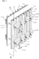
- substantially C-shaped concrete form deformation preventing members 1 are mounted on positions between adjacent vertical reinforcements 72, where spacing fixture mounting holes 76 for receiving spacing fixtures consisting of separators 121, attachments 122 and fastening members 123 are arranged in parallel with the vertical reinforcements 72, as shown in Figs. 1 and 2.
- Male screws 123b are provided on other ends of the fastening members 123, so that pars of thin angular cylindrical form support members 126 of a metal are fixed by support members 124 and nuts 125 which are mounted on the male screws 123b, to be opposed to each other through the respective fastening members 123 for bridging a plurality of transversely arranged form panels 70 with each other.
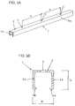
- Each concrete form deformation preventing member 1 has a shape shown in Fig. 3A.
- the concrete form deformation preventing member 1 comprises a thin main plate portion 2 extending in the form of a strip, a pair of side plate portions 3a and 3b extending from both sides of the main plate portion 2 perpendicularly to the main plate portion 2, and a pair of inner extensions 4a and 4b inwardly extending from respective open ends of the side plate portions 3a and 3b substantially in parallel with the main plate portion 2.
- This concrete form deformation preventing member 1 has a substantially C-shaped cross section, as shown in Fig. 3B.
- Through holes 5 are formed in the main plate portion 2 of the concrete form deformation preventing member 1 at pitches of 300 mm or 600 mm, i.e., integral times as long as 300 mm, in coincidence with the spacing fixture mounting holes of each form panel 70 to which the present invention is applied.
- the height (dimension h shown in Fig. 3B) of the side plate portions 3a and 3b is set to substantially coincide with that of the vertical reinforcements 72 of each form panel 70 to which the present invention is applied, and the width (dimension w shown in Fig.
- This dimension w is set in the range of 35 to 120 mm.
- each concrete form deformation preventing member 1 The pair of inner extensions 4a and 4b of each concrete form deformation preventing member 1 are provided for sufficiently ensuring contact areas with the surface of each form panel 70 or for improving bending strength of the concrete form deformation preventing member 1 itself, these inner extensions 4a and 4b may not necessarily be provided if the required strength is not so much high.
- the material for the concrete form deformation preventing member 1 is prepared by molding a sheet metal or from a draw-molded member of fiber reinforced plastic, and this material is properly selected in response to the required strength.
- a draw-molded member of fiber reinforced plastic When a draw-molded member of fiber reinforced plastic is employed, its thickness must be at least 3 mm.
- ends of the spacing fixtures for fixing the opposite form panels 70 to each other at a prescribed space can be mounted on the through holes 5 for fastening/fixing the same with the concrete form deformation preventing members 1 having substantially C-shaped cross sections, whereby the concrete form deformation preventing members 1 can be temporarily fixed by the spacing fixtures themselves in assembling of a concrete form, while the concrete form deformation preventing members 1 can also be clamped/fixed simultaneously with fastening/fixation of the spacing fixtures.
- both sides of portions around the spacing fixture mounting holes 76 are pressed by the respective inner extensions 4a adn 4b of the pairs of side plate portions 3a and 3b, whereby portions immediately close to the spacing fixture mounting holes 76 can be reliably pressed as compared with the case of pressing the same by pairs of pipe members or the like.
- portions immediately close to the spacing fixture mounting holes 76 can be reliably pressed as compared with the case of pressing the same by pairs of pipe members or the like.
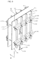
- form deformation preventing members 1 are applied to assembling of a concrete form with a form panel 101 consisting of a fiber reinforced plastic compact having a shape shown in Fig. 15, which has already been proposed in Japanese Patent Laying-Open No. 8-13792 (1996) by the inventor.
- each form panel 101 employed in this embodiment comprises a front plate portion 103, a pair of strip-shaped side plate portions 104, and a pair of strip-shaped rear plate portions 105.
- Fig. 15 is a perspective view of the form panel 101 as viewed from the back.
- This form panel 101 consists of such a long flat plate that the length between the longitudinal ends of the front plate portion 103 is set to be about 10 times as long as that between the cross-directional ends, and its surface is formed flatly.
- the pair of side plate portions 104 define long strip-shaped bodies perpendicularly extending from the cross-directional edges of the front plate portion 103 toward the rear surface side to be opposed to each other, and the surfaces thereof are formed flatly.
- the pair of rear plate portions 105 define long strip-shaped bodies inwardly perpendicularly extending from respective cross-directional forward ends of the side plate portions 104 to face the rear surface of the front plate portion 103. The surfaces thereof are formed flatly, while the forward ends inwardly project to define reinforcing thick portions.
- a plurality of mounting holes 106 are formed along its cross-directional center at prescribed spaces in the longitudinal direction. Further, a plurality of mounting holes 107 are formed in the pair of side plate portions 104 in correspondence to the positions of the mounting holes 106 of the front plate portion 3, and these mounting holes 107 are arranged on positions separated from the surface of the front plate portion 103 at prescribed distances in the cross direction.
- a plurality of mounting holes 108 are formed in the pair of rear plate portions 105 in correspondence to the positions of the mounting holes 106 of the front plate portion 103, and these mounting holes 108 are arranged on positions separated from the surfaces of the side plate portions 104 at the same distances as those between the centers of the mounting holes 107 and the surface of the front plate portion 103 in the cross direction.
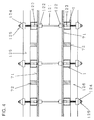
- Fig. 5 is a perspective view showing the concrete form deformation preventing members 1 described with reference to Figs. 3A and 3B, which are applied for assembling a concrete form by transversely arranging a plurality of pairs of such form panels 101 to be opposed to each other at prescribed spaces between the front plate portions 103.
- Fig. 6 is a sectional view taken along the line VI - VI in Fig. 5, and Fig. 7 shows a horizontal section in Fig. 5.
- the pairs of side plate portions 3a and 3b of the concrete form deformation preventing members 1 are mounted so that the open ends thereof are in contact with the rear side surfaces of the front plate portions 103 of the form panels 101 for forming the concrete form to vertically extend along the cross-directional centers.
- the respective concrete form deformation preventing members 1 are fastened/fixed by spacing fixtures consisting of separators 121, attachments 122 and fastening members 123 in the spacing fixture mounting holes 5 thereof.
- pairs of members 1a which are identical to the concrete form deformation preventing members 1 are fixed by support members 124 and nuts 125 as transverse reinforcements.
- the concrete form deformation preventing member 1 according to the present invention is also effectively applicable to assembling of a newly developed form panel 101 while a member having the same shape can be utilized also as a transverse reinforcement, whereby vertical and transverse reinforcements can be defined by members which are absolutely identical to each other, conveniently in consideration of saving of the material cost.
Landscapes
- Engineering & Computer Science (AREA)
- Architecture (AREA)
- Mechanical Engineering (AREA)
- Civil Engineering (AREA)
- Structural Engineering (AREA)
- Forms Removed On Construction Sites Or Auxiliary Members Thereof (AREA)
Abstract
A concrete form deformation preventing member consists of a bar having a substantially C-shaped cross section and comprising a main plate portion (2) which is flat at least on its surface and a horizontal pair of strip-shaped side plate portions (3a, 3b) extending from both sides of the main plate portion toward the rear surface side perpendicularly to the main plate portion (2), and through holes (5) are provided longitudinally along the cross-directional center of the main plate portion (2) at prescribed pitches. In assembling of a concrete form, both end portions of a spacing fixture (122, 122, 123) for fixing a pair of form panels (71, 72) to each other while spacing the same outwardly extending beyond the pair of form panels (71, 72) are inserted in the through holes (5) and the rear surface of the main plate portion (2) is pressed on both end portions of the spacing fixture, whereby open ends of the pair of side plate portions (3a, 3b) come into contact with the rear surfaces of said form panels (71, 72), for preventing deformation of the form panels (71, 72).
Description
- The present invention relates to a concrete form deformation preventing member for preventing deformation of a form panel which is employed for concrete placing or molding of concrete secondary products in construction or civil engineering works, for example, in assembling of a concrete form, and a method of assembling a concrete form with the same.
- In general, a wood form panel prepared by nailing crossbars to a plywood board and a metal form panel prepared by fixing metal ribs to an iron plate or an aluminum plate are known as such form panels. As a typical example of the conventional wood form panel, Fig. 8A shows
form panels 70, each of which is prepared by fastening and fixing aflat plate 71 consisting of plywood to a plurality of reinforcingcrossbars 72 withnails 73. In order to assemble a concrete form withsuch form panels 70, the reinforcingcrossbars 72 of theadjacent form panels 70 are fastened to each other withnails 73, thereby mutually coupling/fixing theform panels 70 with/to each other. Fig. 8B shows an exemplary concrete form having a crossconcrete form portion 74, which is assembled in the aforementioned manner. Theflat plates 71 may be prepared from plastic plates, in place of plywood boards. - With reference to Figs. 9 to 11B, description is now made on an exemplary structure of a conventional concrete form which is assembled by fixing a pair of
such form panels 70 to each other at a prescribed space through a concrete placing source. In this prior art, members which are mainly formed byseparators 121,attachments 122 and clampingmembers 123 are employed as spacing fixtures for fixing theopposite form panels 70 to each other while spacing the same. As shown in Fig. 11A, eachseparator 121 has a pair ofmale screws 121a which are formed on both ends of a bar. Eachmale screw 121a fits with afemale screw 122c which is provided on one end of eachattachment 122 shown in Fig. 11B. Amale screw 122d which is formed on the other end of theattachment 122 to be substantially coaxial with thefemale screw 122c passes through a spacingfixture mounting hole 76 provided in eachform panel 70, so that an end of a substantially truncated-conical presser part 122a of resin which is engaged with the outer periphery of anattachment body part 122b comes into contact with a concrete placing surface of theform panel 70. A female screw 123a which is provided on one end of eachclamping member 123 shown in Fig. 11C fits with themale screw 122d of theattachment 122, whereby theattachment 122 is clamped/fixed to theform panel 70. - A
male screw 123b is provided on the other end of theclamping member 123, so that a pair of thin angular cylindrical form supportmembers 126 of a metal are opposed to each other through eachclamping member 123 by asupport member 124 and anut 125 which are mounted on themale screw 123b, thereby bridging a plurality of transversely arrangedform panels 70 with each other. - However, the aforementioned method of assembling the conventional concrete form has the following problem: In the aforementioned method of assembling the conventional concrete form, each form panel is prepared by mounting
vertical reinforcements 72 on aplywood board 71 having a width W of 900 mm at pitches (lengths P shown in Fig. 12) of about 300 mm, for example, as shown in Fig. 12. Therefore, spacingfixture mounting holes 76 and thevertical reinforcements 72 are at relatively large distances, and hencesuch plywood boards 71, which must be in a state shown in Fig. 10A, are deformed as shown in Fig. 10B, due to dispersion in clamping strength of thenuts 125 against themale screws 123b of theclamping members 123. Namely, although the distance between theopposite plywood boards 71 which is set by theseparators 121 and theattachments 122 is maintained at a constant level, theplywood board 71 subjected to larger clamping force is outwardly swollen and that subjected to smaller clamping force is inwardly depressed if thenuts 125 fitting with the pairs of clampingmembers 123 for fastening/fixing theopposite form panels 70 to each other are different in clamping force from each other. - When the form panels are irregularized in the aforementioned manner, the surface of the molded concrete is also irregularized to exert a significant influence on subsequent execution. Consequently, the surface performance of concrete such as smoothness or surface finish is disadvantageously deteriorated.
- In order to solve the aforementioned problem of the prior art, a pair of
round pipes 127 may be interposed between eachplywood board 71 and each thin angular cylindricalform support member 126 around both sides of each spacingfixture mounting hole 76 as shown in Fig. 13, for example. In this case, deformation of theplywood board 71 caused by clamping is suppressed to some extent. However, theround pipes 127 are in line contact with the surface of theplywood board 71, and hence the space between the contact lines of the pair ofround pipes 127 with theplywood board 71 is increased. Thus, the effect for suppressing deformation of theplywood board 71 is insufficient. - In place of the
round pipes 127, a pair of thin angularcylindrical pipes 128 may be employed as reinforcements for preventing deformation of theplywood board 71, as shown in Fig. 14. Such thin angularcylindrical pipes 128 are in surface contact with the surface of theplywood board 71, and the space between the contact portions of thesepipes 128 can be minimized. Thus, the effect for preventing deformation of theplywood board 71 is remarkably improved as compared with the case of employing theround pipes 127. - In this case, however, the thin angular
cylindrical members 128 cannot be fixed until each transverse reinforcement (thin angular cylindrical form support member) 126 is fixed and clamped If these thin angularcylindrical pipes 128 are temporarily fixed for performing the assembling operation, the number of the reinforcements is increased and some parts are required for the temporary fixation, resulting in unpreferable problems in both of working efficiency and the material cost. - An object of the present invention is to provide a concrete form deformation preventing member improving an effect of preventing deformation of a form panel in assembling of a concrete form without damaging workability and remarkably increasing the material cost.
- In order to attain the aforementioned object, the concrete form deformation preventing member according to the present invention consists of a bar having a substantially C-shaped cross section and comprising a strip-shaped main plate portion which is flat at least on its surface, and a horizontal pair of strip-shaped side plate portions extending from both sides of the main plate portion toward the rear surface side perpendicularly to the main plate portion. Through holes are provided at the cross-directional center of the main plate portion of the bar at prescribed pitches along the longitudinal direction.
- According to the inventive concrete form deformation preventing member having the aforementioned structure, the pitches of the through holes are equalized with those of spacing fixture mounting holes of a form panel to which the present invention is applied so that the spacing fixture mounting holes of the form panel and the through holes of the inventive concrete form deformation preventing member corresponding thereto are coaxial with each other, end portions of spacing fixtures are inserted in both of the spacing fixture mounting holes and the through holes and fastened by nuts or the like, whereby the fixtures can be so fixed that front ends of the side plate portions press the surface of the form panel from both sides of portions close to the spacing fixture mounting holes without separately providing temporary fixing means in particular. In relation to a line of spacing fixture mounting holes of the form panel, therefore, both sides of portions close to the spacing fixture mounting holes can be reliably pressed by only one bar, leading to such specific effects that working efficiency is extremely improved, the number of parts can be minimized and the material cost is not remarkably increased.
- The pitches of the through holes in the inventive concrete form deformation preventing member are set substantially at integral times as long as 300 mm. This is because the pitches of the spacing fixture mounting holes of the form panel are defined to be set at integral times as long as 300 mm.
- In consideration of dimensions of members for fastening/fixing the spacing fixtures, the width of the main plate portion of the inventive concrete form deformation preventing member is preferably set to be at least 35 mm and not more than 120 mm. No spaces for fastening/fixing the spacing fixtures are ensured if the width of the main plate portion is less than the above numerical range, while spaces between contact portions pressing both sides of the spacing fixture mounting holes of the form panel are so increased that the effect of preventing deformation cannot be sufficiently attained.
- The inventive method of assembling a concrete form with the aforementioned concrete form deformation preventing member according to the present invention is adapted to insert both end portions of spacing fixtures outwardly projecting beyond a pair of opposite form panels in the through holes of the aforementioned concrete form deformation preventing member according to the present invention and pressing the rear surface of the main plate portion of the concrete form deformation preventing member on both end portions of the spacing fixtures, so that front ends of the pair of side plate portions come into contact with the rear surfaces of the form panels for preventing deformation of the form panels.
- The concrete form deformation preventing member has a substantially C-shaped cross section and the pitches of the through holes provided in the main plate portion are equalized with those of the spacing fixture mounting holes provided in the form panels, whereby end portions of the spacing fixtures for fixing the pair of opposite form panels to each other while spacing the same can be inserted in the through holes so that the concrete form deformation preventing member can perform temporary fixation and fixation before and after fastening of the spacing fixtures respectively without separately providing independent means in particular. Therefore, the workability in assembling of the concrete form is improved as compared with the conventional method, while the effect of preventing deformation of the concrete form can be reliably attained without remarkably increasing the material cost.
- In more concrete terms, the method of assembling a concrete form with the inventive concrete form deformation preventing member comprises the following steps: First, a plurality of pairs of form panels provided with spacing fixture mounting holes at the same pitches as those of through holes of the concrete form deformation preventing member in the longitudinal direction at axial centers are adjacently arranged in the cross direction, to be opposed to each other every pair for forming a concrete placing portion.
- Then, a plurality of spacing fixtures for fixing the pairs of opposite form panels to each other while keeping the same at prescribed distances are inserted in opposite spacing fixture mounting holes of the opposite form panels and mounted for bridging the opposite pairs of form panels with each other. Thereafter both end portions of the plurality of mounted spacing fixtures outwardly projecting from the respective ones of the opposite pairs of form panels are inserted in the through holes while open ends of the side plate portions of the concrete form deformation preventing member are fastened/fixed by fastening means provided on both end portions of the respective ones of the spacing fixtures while pressing the rear surface of the main plate portion of the concrete form deformation preventing member.
- The foregoing and other objects, features, aspects and advantages of the present invention will become more apparent from the following detailed description of the present invention when taken in conjunction with the accompanying drawings.
-
- Fig. 1 is a partially fragmented exploded perspective view showing a method of assembling a concrete form according to an embodiment of the present invention;
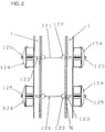
- Fig. 2 is a sectional view taken along the line II - II in Fig. 1;
- Fig. 3A is a partially fragmented perspective view of a concrete form
deformation preventing member 1 employed in the embodiment of the present invention, and Fig. 3B is an enlarged cross sectional view along the center of athrough hole 5 of the concrete formdeformation preventing member 1; - Fig. 4 is a horizontal sectional view showing an assembled state of the concrete form in the embodiment of the present invention;
- Fig. 5 is a partially fragmented exploded perspective view showing a method of assembling a concrete form according to another embodiment of the present invention;
- Fig. 6 is a sectional view taken along the line VI - VI in Fig. 5;
- Fig. 7 shows a horizontal section in Fig. 5;
- Fig. 8A is a perspective view showing a state of coupling/fixing conventional wood form panels to each other by nailing, and Fig. 8B is a plan view showing a cross concrete form assembled with the form panels shown in Fig. 8A;
- Fig. 9 is a partially fragmented perspective view showing a wood concrete form assembled by a conventional method;
- Fig. 10A is a sectional view taken along the line X - X in Fig. 9, and Fig. 10B is a sectional view corresponding to Fig. 10A, showing form panels deformed by dispersion in clamping strength of
nuts 125; - Figs. 11A to 11C illustrate respective elements of a generally employed spacing fixture in an exploded manner;
- Fig. 12 is a perspective view showing a conventional typical wood form panel;
- Fig. 13 is a plan view showing a conventional method of preventing deformation of a form panel with round pipe members;
- Fig. 14 is a plan view showing a conventional method of preventing deformation of a form panel with thin angular pipe members; and
- Fig. 15 is a perspective view showing a form panel already proposed in Japanese Patent Laying-Open No. 8-13792 (1996) by the inventor.
- An embodiment of the present invention is now described with reference to the drawings.
- In this embodiment, the present invention is applied to assembling of the conventional wood concrete form described with reference to Figs. 11 to 14. In this embodiment, substantially C-shaped concrete form
deformation preventing members 1 are mounted on positions between adjacentvertical reinforcements 72, where spacingfixture mounting holes 76 for receiving spacing fixtures consisting ofseparators 121,attachments 122 andfastening members 123 are arranged in parallel with thevertical reinforcements 72, as shown in Figs. 1 and 2. -
Male screws 123b are provided on other ends of thefastening members 123, so that pars of thin angular cylindricalform support members 126 of a metal are fixed bysupport members 124 andnuts 125 which are mounted on themale screws 123b, to be opposed to each other through therespective fastening members 123 for bridging a plurality of transversely arrangedform panels 70 with each other. - Each concrete form
deformation preventing member 1 has a shape shown in Fig. 3A. Namely, the concrete formdeformation preventing member 1 comprises a thinmain plate portion 2 extending in the form of a strip, a pair of side plate portions 3a and 3b extending from both sides of themain plate portion 2 perpendicularly to themain plate portion 2, and a pair ofinner extensions 4a and 4b inwardly extending from respective open ends of the side plate portions 3a and 3b substantially in parallel with themain plate portion 2. This concrete formdeformation preventing member 1 has a substantially C-shaped cross section, as shown in Fig. 3B. - Through
holes 5 are formed in themain plate portion 2 of the concrete formdeformation preventing member 1 at pitches of 300 mm or 600 mm, i.e., integral times as long as 300 mm, in coincidence with the spacing fixture mounting holes of eachform panel 70 to which the present invention is applied. The height (dimension h shown in Fig. 3B) of the side plate portions 3a and 3b is set to substantially coincide with that of thevertical reinforcements 72 of eachform panel 70 to which the present invention is applied, and the width (dimension w shown in Fig. 3B) of themain plate portion 2 is so set that fastening portions on both ends of spacing fixtures for fixing theopposite form panels 70 to each other while spacing the same, i.e., thefastening members 123 or the like, can be inserted from the open ends of the concrete formdeformation preventing member 1. This dimension w is set in the range of 35 to 120 mm. - The pair of
inner extensions 4a and 4b of each concrete formdeformation preventing member 1 are provided for sufficiently ensuring contact areas with the surface of eachform panel 70 or for improving bending strength of the concrete formdeformation preventing member 1 itself, theseinner extensions 4a and 4b may not necessarily be provided if the required strength is not so much high. - The material for the concrete form
deformation preventing member 1 is prepared by molding a sheet metal or from a draw-molded member of fiber reinforced plastic, and this material is properly selected in response to the required strength. When a draw-molded member of fiber reinforced plastic is employed, its thickness must be at least 3 mm. - According to this embodiment, ends of the spacing fixtures for fixing the
opposite form panels 70 to each other at a prescribed space can be mounted on the throughholes 5 for fastening/fixing the same with the concrete formdeformation preventing members 1 having substantially C-shaped cross sections, whereby the concrete formdeformation preventing members 1 can be temporarily fixed by the spacing fixtures themselves in assembling of a concrete form, while the concrete formdeformation preventing members 1 can also be clamped/fixed simultaneously with fastening/fixation of the spacing fixtures. Further, both sides of portions around the spacingfixture mounting holes 76 are pressed by the respective innerextensions 4a adn 4b of the pairs of side plate portions 3a and 3b, whereby portions immediately close to the spacingfixture mounting holes 76 can be reliably pressed as compared with the case of pressing the same by pairs of pipe members or the like. In case of fitting the nuts 125 with themale screws 123b of thefastening members 123 of the spacing fixtures, therefore, excessive clamping of thenuts 125 is prevented due to restriction by the height (dimension h) of the side plate portions 3a and 3b of the concrete formdeformation preventing members 1. Consequently, the problem of dispersion in clamping strength of therespective nuts 125 on both ends of the spacing fixtures is solved, thereby preventing deformation of the form panels in the vicinity of the spacingfixture mounting holes 76, which has been problematic in the prior art. Following this, surface performance of molded concrete can be improved. - Another embodiment of the present invention is now described with reference to Figs. 5 to 7 and Fig. 15. In this embodiment, form
deformation preventing members 1 according to the present invention are applied to assembling of a concrete form with aform panel 101 consisting of a fiber reinforced plastic compact having a shape shown in Fig. 15, which has already been proposed in Japanese Patent Laying-Open No. 8-13792 (1996) by the inventor. - Referring to Fig. 15, each
form panel 101 employed in this embodiment comprises afront plate portion 103, a pair of strip-shapedside plate portions 104, and a pair of strip-shapedrear plate portions 105. Fig. 15 is a perspective view of theform panel 101 as viewed from the back. - This
form panel 101 consists of such a long flat plate that the length between the longitudinal ends of thefront plate portion 103 is set to be about 10 times as long as that between the cross-directional ends, and its surface is formed flatly. The pair ofside plate portions 104 define long strip-shaped bodies perpendicularly extending from the cross-directional edges of thefront plate portion 103 toward the rear surface side to be opposed to each other, and the surfaces thereof are formed flatly. Further, the pair ofrear plate portions 105 define long strip-shaped bodies inwardly perpendicularly extending from respective cross-directional forward ends of theside plate portions 104 to face the rear surface of thefront plate portion 103. The surfaces thereof are formed flatly, while the forward ends inwardly project to define reinforcing thick portions. - In the
front plate portion 103 of theform panel 101, a plurality of mountingholes 106 are formed along its cross-directional center at prescribed spaces in the longitudinal direction. Further, a plurality of mountingholes 107 are formed in the pair ofside plate portions 104 in correspondence to the positions of the mountingholes 106 of thefront plate portion 3, and these mountingholes 107 are arranged on positions separated from the surface of thefront plate portion 103 at prescribed distances in the cross direction. In addition, a plurality of mountingholes 108 are formed in the pair ofrear plate portions 105 in correspondence to the positions of the mountingholes 106 of thefront plate portion 103, and these mountingholes 108 are arranged on positions separated from the surfaces of theside plate portions 104 at the same distances as those between the centers of the mountingholes 107 and the surface of thefront plate portion 103 in the cross direction. - Fig. 5 is a perspective view showing the concrete form
deformation preventing members 1 described with reference to Figs. 3A and 3B, which are applied for assembling a concrete form by transversely arranging a plurality of pairs ofsuch form panels 101 to be opposed to each other at prescribed spaces between thefront plate portions 103. Fig. 6 is a sectional view taken along the line VI - VI in Fig. 5, and Fig. 7 shows a horizontal section in Fig. 5. - Referring to Figs. 5 to 7, the pairs of side plate portions 3a and 3b of the concrete form
deformation preventing members 1 are mounted so that the open ends thereof are in contact with the rear side surfaces of thefront plate portions 103 of theform panels 101 for forming the concrete form to vertically extend along the cross-directional centers. Similarly to the embodiment described with reference to Figs. 1 to 4, the respective concrete formdeformation preventing members 1 are fastened/fixed by spacing fixtures consisting ofseparators 121,attachments 122 andfastening members 123 in the spacingfixture mounting holes 5 thereof. - In this embodiment, pairs of
members 1a which are identical to the concrete formdeformation preventing members 1 are fixed bysupport members 124 andnuts 125 as transverse reinforcements. - Thus, the concrete form
deformation preventing member 1 according to the present invention is also effectively applicable to assembling of a newly developedform panel 101 while a member having the same shape can be utilized also as a transverse reinforcement, whereby vertical and transverse reinforcements can be defined by members which are absolutely identical to each other, conveniently in consideration of saving of the material cost. - Although the present invention has been described and illustrated in detail, it is clearly understood that the same is by way of illustration and example only and is not to be taken by way of limitation, the spirit and scope of the present invention being limited only by the terms of the appended claims.
Claims (9)
- A concrete form deformation preventing member, consisting of a bar having a substantially C-shaped cross section and comprising:a strip-shaped main plate portion (2) being flat at least on its surface; anda horizontal pair of strip-shaped side plate portions (3a, 3b) extending from both sides of said main plate portion (2) toward the rear surface side perpendicularly to said main plate portion (2),through holes (5) being provided along the cross-directional center of said main plate portion (2) at prescribed pitches in the longitudinal direction.
- The concrete form deformation preventing member in accordance with claim 1, wherein said pitches of said through holes (5) are substantially integral times as long as 300 mm.
- The concrete form deformation preventing member in accordance with claim 1 or 2, wherein the width of said main plate portion (2) is at least 35 mm and not more than 120 mm.
- A method of assembling a concrete form by arranging and fixing a pair of form panels (71, 72) to be opposed to each other while keeping a prescribed distance by providing a spacing fixture (121, 122, 123) therebetween and preventing deformation of said form panels (71, 72) with a concrete form deformation preventing member (1), whereinsaid concrete form deformation preventing member (1) consists of a bar having a substantially C-shaped cross section and including:a strip-shaped main plate portion (2) being flat at least on its surface, anda horizontal pair of strip-shaped side plate portions (3a, 3b) extending from both sides of said main plate portion (2) toward the rear surface side perpendicularly to said main plate portion (2),with through holes (5) being provided along the cross-directional center of said main piate portion (2) at prescribed pitches in the longitudinal direction, andboth end portions of said spacing fixture outwardly extending beyond said pair of form panels (71, 72) are inserted in said through holes (5) of said concrete form deformation preventing member (1) for pressing the rear surface of said main plate portion (2) of said concrete form deformation preventing member (1) on both end portions of said spacing fixture, thereby bringing open ends of said pair of side plate portions (3a, 3b) into contact with the rear surfaces of said form panels (71, 72) and preventing deformation of said form panels (71, 72).
- The method of assembling a concrete form in accordance with claim 4 , wherein said concrete form deformation preventing member (1) is prepared from that having said through holes (5) being at pitches substantially integral times as long as 300 mm.
- The method of assembling a concrete form in accordance with claim 4 or 5, wherein said concrete form deformation preventing member (1) is prepared from that having said main plate portion (2) being at a width of at least 35 mm and 120 mm.
- A method of assembling a concrete form with a concrete form deformation preventing member (1) consisting of a bar having a substantially C-shaped cross section and including:a strip-shaped main plate portion (2) being flat at least on its surface, anda horizontal pair of strip-shaped side plate portions (3a, 3b) extending from both sides of said main plate portion (2) toward the rear surface side perpendicularly to said main plate portion (2),with through holes (5) being provided along the cross-directional center of said main plate portion (2) at prescribed pitches in the longitudinal direction, said method comprising the steps of:arranging a plurality of pairs of form panels (71, 72) being provided with spacing fixture mounting holes (76) longitudinally along cross-sectional centers at the same pitches as said through holes (5) of said concrete form deformation preventing member to be cross-directionally adjacent to each other and opposed to each other every pair for forming a concrete placing portion;mounting a plurality of spacing fixtures (121, 122, 123) for fixing said opposite pairs of form panels (71, 72) to each other while keeping prescribed distances by inserting the same in opposite said spacing fixture mounting holes (76) of opposite said form panels (71, 72) for bridging opposite said pairs of form panels (71, 72) with each other; andinserting both end portions of said plurality of spacing fixtures outwardly projecting from respective ones of said opposite pairs of form panels (71, 72) in said through holes (5) while fastening/fixing open ends of said side plate portions (3a, 3b) of said concrete form deformation preventing member (1) by fastening means (123) being provided on said both end portions of respective ones of said spacing fixtures while pressing the rear surface of said main plate portion (2) of each said concrete form deformation preventing member.
- The method of assembling a concrete form in accordance with claim 7, wherein said concrete form deformation preventing member (1) is prepared from that having said through holes (5) being at pitches substantially integral times as long as 300 mm.
- The method of assembling a concrete form in accordance with claim 7 or 8, wherein said concrete form deformation preventing member (1) is prepared from that having said main plate portion (2) being at a width of at least 35 mm and 120 mm.
Applications Claiming Priority (2)
| Application Number | Priority Date | Filing Date | Title |
|---|---|---|---|
| JP200864/95 | 1995-08-07 | ||
| JP7200864A JPH0949320A (en) | 1995-08-07 | 1995-08-07 | Concrete form deformation preventive member and concrete form assembling method using it |
Publications (1)
| Publication Number | Publication Date |
|---|---|
| EP0758043A1 true EP0758043A1 (en) | 1997-02-12 |
Family
ID=16431499
Family Applications (1)
| Application Number | Title | Priority Date | Filing Date |
|---|---|---|---|
| EP96111090A Ceased EP0758043A1 (en) | 1995-08-07 | 1996-07-10 | Concrete form deformation preventing member and method of assembling concrete form with the same |
Country Status (6)
| Country | Link |
|---|---|
| EP (1) | EP0758043A1 (en) |
| JP (1) | JPH0949320A (en) |
| KR (1) | KR970011235A (en) |
| CN (1) | CN1142561A (en) |
| CA (1) | CA2181952A1 (en) |
| TW (1) | TW294751B (en) |
Cited By (1)
| Publication number | Priority date | Publication date | Assignee | Title |
|---|---|---|---|---|
| US20180258637A1 (en) * | 2015-07-31 | 2018-09-13 | Sei SAIHARA | Support member, concrete placing form, and method for constructing concrete structure |
Families Citing this family (9)
| Publication number | Priority date | Publication date | Assignee | Title |
|---|---|---|---|---|
| CN102912779A (en) * | 2012-11-07 | 2013-02-06 | 江苏省交通工程集团有限公司 | End sealing plate fixing structure of lift wall construction |
| CN104278632A (en) * | 2013-07-09 | 2015-01-14 | 宏润建设集团股份有限公司 | Bridge main tower creeping formwork and manufacturing method thereof |
| FR3019572A1 (en) * | 2014-04-03 | 2015-10-09 | Dominique Tallarida | MOLDED, SELF-STABILIZING FORMWORK PLATE FOR WALLS AND VENTS |
| CN104818843A (en) * | 2015-04-20 | 2015-08-05 | 常州展华机器人有限公司 | Large-scale shear wall drilling-free mounting template and use method |
| CN105406479A (en) * | 2015-12-23 | 2016-03-16 | 镇江向荣智能电气有限公司 | Novel active filter fixing framework |
| CN106193387A (en) * | 2016-08-31 | 2016-12-07 | 柳州市杰特建材有限责任公司 | Cast-in-place combined wall |
| KR102281943B1 (en) * | 2018-09-19 | 2021-07-26 | (주)이에스씨엠 | Device for Connecting the Pannel of Concrete Form Assembly |
| CN113107189B (en) * | 2021-04-16 | 2023-01-03 | 山东华铝模板有限公司 | Aluminum template structure |
| CN114737748A (en) * | 2022-04-08 | 2022-07-12 | 江苏省送变电有限公司 | Template for improving appearance quality of transformer substation main transformer firewall and construction method |
Citations (5)
| Publication number | Priority date | Publication date | Assignee | Title |
|---|---|---|---|---|
| US2816345A (en) * | 1955-06-22 | 1957-12-17 | Symons Clamp & Mfg Co | Concrete wall form |
| US3385557A (en) * | 1965-09-15 | 1968-05-28 | Robert D. Rambelle | Multi-purpose building member |
| DE1917639A1 (en) * | 1969-04-05 | 1970-10-08 | Symons Mfg Company | Concrete wall formwork with devices for the even distribution of the forces caused by the loose concrete |
| DE2426708A1 (en) * | 1974-06-01 | 1975-12-04 | Josef Maier | Wide-area variously curved concrete formwork - with support's shanks laterally movable near membrane, and varying - length chord sections |
| EP0062420A1 (en) * | 1981-03-27 | 1982-10-13 | Aluma Systems Incorporated | Concrete forming structures |
-
1995
- 1995-08-07 JP JP7200864A patent/JPH0949320A/en active Pending
-
1996
- 1996-04-26 TW TW085105003A patent/TW294751B/en active
- 1996-05-29 KR KR1019960018488A patent/KR970011235A/en not_active Application Discontinuation
- 1996-07-10 EP EP96111090A patent/EP0758043A1/en not_active Ceased
- 1996-07-24 CA CA002181952A patent/CA2181952A1/en not_active Abandoned
- 1996-07-31 CN CN96108531A patent/CN1142561A/en active Pending
Patent Citations (5)
| Publication number | Priority date | Publication date | Assignee | Title |
|---|---|---|---|---|
| US2816345A (en) * | 1955-06-22 | 1957-12-17 | Symons Clamp & Mfg Co | Concrete wall form |
| US3385557A (en) * | 1965-09-15 | 1968-05-28 | Robert D. Rambelle | Multi-purpose building member |
| DE1917639A1 (en) * | 1969-04-05 | 1970-10-08 | Symons Mfg Company | Concrete wall formwork with devices for the even distribution of the forces caused by the loose concrete |
| DE2426708A1 (en) * | 1974-06-01 | 1975-12-04 | Josef Maier | Wide-area variously curved concrete formwork - with support's shanks laterally movable near membrane, and varying - length chord sections |
| EP0062420A1 (en) * | 1981-03-27 | 1982-10-13 | Aluma Systems Incorporated | Concrete forming structures |
Cited By (1)
| Publication number | Priority date | Publication date | Assignee | Title |
|---|---|---|---|---|
| US20180258637A1 (en) * | 2015-07-31 | 2018-09-13 | Sei SAIHARA | Support member, concrete placing form, and method for constructing concrete structure |
Also Published As
| Publication number | Publication date |
|---|---|
| CA2181952A1 (en) | 1997-02-08 |
| CN1142561A (en) | 1997-02-12 |
| KR970011235A (en) | 1997-03-27 |
| TW294751B (en) | 1997-01-01 |
| JPH0949320A (en) | 1997-02-18 |
Similar Documents
| Publication | Publication Date | Title |
|---|---|---|
| EP0679781B1 (en) | Concrete molding form member, and form member space holder and form member connector for assembling the same | |
| KR100704779B1 (en) | Lip channel steel and connecting fitting thereof | |
| CA2391880C (en) | Apparatus for reinforcing a portion of a metal joist adjacent an opening therethrough and methods for forming reinforced openings in metal support members | |
| EP0758043A1 (en) | Concrete form deformation preventing member and method of assembling concrete form with the same | |
| US6296224B1 (en) | Concrete form member | |
| EP1749947B1 (en) | Anchoring insert for embedding in concrete | |
| CN215977653U (en) | Node structure for building and building structure | |
| KR950003708Y1 (en) | Scaffolding clamp | |
| KR100472603B1 (en) | concrete side panel and connecting structure thereof | |
| CA2206191C (en) | Wallform panel and side rail | |
| CN213329822U (en) | Fastener and panel connection structure thereof | |
| US7331148B2 (en) | Stud for concrete forms and forms using such studs | |
| KR200294794Y1 (en) | concrete side panel and connecting structure thereof | |
| CN218760750U (en) | Quick-mounting fastening connector | |
| CN219973884U (en) | Semi-assembled floor template structure | |
| CN212053372U (en) | A mounting for decorative board is assembled | |
| CN116181065B (en) | Aluminum and wood template connecting structure | |
| CN211691718U (en) | Steel plate bin reinforcing rib convenient to install | |
| KR200171212Y1 (en) | Setting apparatus for ceiling finishing | |
| KR970005528Y1 (en) | Prefabricated form | |
| JPH0249755Y2 (en) | ||
| CN113482174A (en) | Panel connection structure and panel | |
| KR200277535Y1 (en) | Structure for assembling a panel of an air conditioner | |
| JPH0240192Y2 (en) | ||
| JPS626187Y2 (en) |
Legal Events
| Date | Code | Title | Description |
|---|---|---|---|
| PUAI | Public reference made under article 153(3) epc to a published international application that has entered the european phase |
Free format text: ORIGINAL CODE: 0009012 |
|
| AK | Designated contracting states |
Kind code of ref document: A1 Designated state(s): AT BE CH DE DK ES FI FR GB GR IT LI LU NL PT SE |
|
| 17P | Request for examination filed |
Effective date: 19970729 |
|
| 17Q | First examination report despatched |
Effective date: 19971010 |
|
| GRAG | Despatch of communication of intention to grant |
Free format text: ORIGINAL CODE: EPIDOS AGRA |
|
| STAA | Information on the status of an ep patent application or granted ep patent |
Free format text: STATUS: THE APPLICATION HAS BEEN REFUSED |
|
| 18R | Application refused |
Effective date: 19980904 |