EP0757005A1 - Kindersicherer Verschluss mit Anzeigeelement für seinen Zustand - Google Patents
Kindersicherer Verschluss mit Anzeigeelement für seinen Zustand Download PDFInfo
- Publication number
- EP0757005A1 EP0757005A1 EP96810511A EP96810511A EP0757005A1 EP 0757005 A1 EP0757005 A1 EP 0757005A1 EP 96810511 A EP96810511 A EP 96810511A EP 96810511 A EP96810511 A EP 96810511A EP 0757005 A1 EP0757005 A1 EP 0757005A1
- Authority
- EP
- European Patent Office
- Prior art keywords
- cap
- closure
- child
- top wall
- outer cap
- Prior art date
- Legal status (The legal status is an assumption and is not a legal conclusion. Google has not performed a legal analysis and makes no representation as to the accuracy of the status listed.)
- Withdrawn
Links
Images


Classifications
-
- B—PERFORMING OPERATIONS; TRANSPORTING
- B65—CONVEYING; PACKING; STORING; HANDLING THIN OR FILAMENTARY MATERIAL
- B65D—CONTAINERS FOR STORAGE OR TRANSPORT OF ARTICLES OR MATERIALS, e.g. BAGS, BARRELS, BOTTLES, BOXES, CANS, CARTONS, CRATES, DRUMS, JARS, TANKS, HOPPERS, FORWARDING CONTAINERS; ACCESSORIES, CLOSURES, OR FITTINGS THEREFOR; PACKAGING ELEMENTS; PACKAGES
- B65D50/00—Closures with means for discouraging unauthorised opening or removal thereof, with or without indicating means, e.g. child-proof closures
- B65D50/02—Closures with means for discouraging unauthorised opening or removal thereof, with or without indicating means, e.g. child-proof closures openable or removable by the combination of plural actions
- B65D50/04—Closures with means for discouraging unauthorised opening or removal thereof, with or without indicating means, e.g. child-proof closures openable or removable by the combination of plural actions requiring the combination of simultaneous actions, e.g. depressing and turning, lifting and turning, maintaining a part and turning another one
- B65D50/041—Closures with means for discouraging unauthorised opening or removal thereof, with or without indicating means, e.g. child-proof closures openable or removable by the combination of plural actions requiring the combination of simultaneous actions, e.g. depressing and turning, lifting and turning, maintaining a part and turning another one the closure comprising nested inner and outer caps or an inner cap and an outer coaxial annular member, which can be brought into engagement to enable removal by rotation
Definitions
- a condition indicating child-resistant closure is disclosed in Applicant's U.S. Patent 4,998,632, wherein an inner cap is adapted to be threadably mounted on a container and an outer cap is freely rotatable on the inner cap and normally spring biased upwardly in spaced relation-ship to the inner cap, but axially movable downwardly and rotatable relative to the inner cap, whereby the inner and outer caps can be interconnected for removal of the closure from the container.
- An indicating post is mounted on the top wall of the inner cap and is adapted to extend through an aperture in the top wall of the outer cap when the inner and outer caps are interconnected for removal from the closure, to thereby indicate the non-child-resistant mode of the cap assembly. When the outer cap is biased upwardly, the indicated post is positioned in the space between the inner and outer caps and therefore not visible, to thereby indicate the child-resistant mode of the closure.
- condition indicating child-resistant closure of the present invention is of the type disclosed in the above-mentioned patent and is an improvement thereon by eliminating the intricately molded plastic parts, such as the ramps and ramp lips, and constructing and arranging the components of the closure with more simply molded parts, and to render it more user-friendly for adults.
- the condition indicating child-resistant closure of the present invention comprises, essentially, a three component assembly including an inner cap having a recessed top wall and a vertically extending indicating post integral therewith and adapted to extend through an aperture in the top wall of an outer cap freely rotatable on the inner cap.
- a bridge member is positioned in the recess of the inner cap top wall and freely rotatable on the indicating post between a first position prohibiting the inner and outer caps from being interconnected for removal from the container, and a second position permitting the manipulation of the outer cap relative to the inner cap for interconnecting the inner and outer caps for removal of the closure from the container.
- Depending flexible fingers are integral with the inner surface of the top wall of the outer cap and are adapted to engage the bridge member for moving the bridge member alternately between the two positions.
- Diametrically disposed stop members are integral with the top wall of the inner cap and extend upwardly therefrom and are engageable with the bridge member to limit its rotary movement between the two positions.
- a coil spring is mounted in coaxial relation-ship with the indicating post and is positioned between the bridge member and the inner surface of the top wall of the outer cap, whereby the outer cap is biased outwardly relative to the inner cap, and the indicating post is contained in the space between the inner and outer caps.
- the inner and outer caps are interconnected for removing the closure from the container by a pair of circumferentially spaced, radially inwardly extending lugs integral with the inner surface of the skirt portion of the outer cap cooperating with circumferentially spaced axially extending slots communicating with respective circumferentially extending slots formed in the skirt portion of the inner cap.
- Depending leg members are integral with the inner surface of the top wall of the outer cap and engage the bridge member when it has been rotated to the first position to prevent axial movement of the outer cap relative to the inner cap for engagement of the lugs with the slots.
- the depending leg members being free of the bridge member when the bridge member has been rotated to the second position, thereby allowing the lugs to enter the slots for the connection of the inner cap with the outer cap.
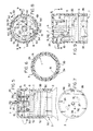
- the condition indicating child-resistant closure of the present invention comprises an inner cap 1, adapted to be threadably mounted on the neck 2 of a medicine bottle, and an outer cap 3 having a top wall 3a and a depending side wall forming a skirt 3b having, at its lower end, an inwardly extending annular bead 3c engageable with a similarly configured shoulder la provided on the outer wall surface of the inner cap 1, whereby the inner and outer caps 1 and 3 are interconnected and freely rotatable relative to each other.
- the outer cap 3 is provided with a pair of radially inwardly extending, diametrically opposed lugs 3d, 3e formed on the inner wall surface of the skirt 3b of the outer cap 3 and engageable with a peripheral edge portion 1b provided on the top of the inner cap 1, whereby the outer cap 3 is held upwardly in spaced relationship to the inner cap 1, and the closure is in a child-resistant mode, wherein the outer cap 3 is freely rotatable on the inner cap 1.
- the side wall of the inner cap 1 is provided with a pair of circumferentially extending slots 1c and 1d, each of which communicate at one end thereof with an upwardly inclined axially extending slot 1e, and 1f, respectively.
- a vertically extending indicating post 4 is fixedly mounted on the inner top cap wall 1g which is positioned below the peripheral edge portion 1b, to thereby provide a recess 1h in the top of the inner cap 1.
- the post 4 is in alignment with an opening 3f provided in the top wall of the outer cap 3, whereby when the closure is in the child-resistant mode, the post 4 is positioned within the space 5 between the top wall 1g of the inner cap 1 and the top wall 3a of the outer cap 3 and below the top of opening 3f, and, therefore, not visible outside of the closure, to thereby indicate the child-resistant mode of the closure, as shown in Figs. 2, 4 and 9.
- the post 4 is adapted to extend through the opening 3f in the outer cap 3 and above the top wall 3a thereof, when the outer cap 3 has been moved inwardly to an interlocked position with the inner cap 1, to be described more fully hereinafter, and therefore visible outside the closure, to thereby indicate the non-child-resistant mode of the closure, as shown in Fig. 5.
- a bridge member 6 is supported on the top wall 1g of the inner cap 1 and is freely rotatable on the indicating post 4, and a coil spring 7 is positioned in coaxial relationship with the indicating post 4 and mounted between the bridge member 6 and the top wall 3a of the outer cap 3 to provide an upwardly biasing force to the outer cap lugs 3d and 3e within their respective circumferential slots 1c and 1d, as shown in Fig. 5.
- the bridge member 6 comprises a rotor having oppositely extending vane portions 6a, 6b having integral upwardly extending radially spaced posts 6c, 6d.
- a pair of flexible fingers 3g and 3h are integral with and depend from the top wall 3a of the outer cap 3 and are adapted to engage the posts 6d for rotating the bridge member 6 alternately between stop members 1h and 1i integral with, and extending upwardly from, the top wall 1g of the inner cap 1.
- a pair of depending leg members 3i and 3j are also integral with the top wall 3a of the outer cap 3 and are adapted to become axially aligned with the posts 6c when the outer cap 3 has been rotated in a counter-clockwise direction and the lugs 3d and 3e in the outer cap 3 are aligned with the axial extending slots 1e and 1f on the inner cap.
- the posts 6c and depending leg members 3i and 3j are located on the same radius from indicating post 4, and posts 6d and flexible fingers 3g and 3h are located on the same spaced radius from indicating post 4.
- the terminal ends of the depending leg members 3i and 3j are spaced slightly above the upper terminal ends of posts 6c so that they pass each other during normal rotation of outer cap 3 on inner cap 1.
- the counter-clockwise movement of the outer cap 3 also results in a counter-clockwise movement of the bridge member 6 by flexible finger 3g engaging post 6d, as shown in phantom lines in Fig. 8, so that the vanes 6a and 6b abut the stop members 1h and 1i on opposite sides thereof, as shown in full lines in Fig. 8.
- the bridge member 6 is positioned to take over the blocking function of upper peripheral edge portion 1b, by registering the tops of posts 6c with the lower ends of leg members 3i and 3j thus blocking downward movement of the lugs 3d and 3e on the outer cap 3 into axial slots 1e and 1f on the inner cap 1.
- the outer cap 3 is rotated in a clockwise direction.
- the flexible finger 3g engages the upper end of post 6d of the vane portion 6a, as shown in Fig. 1, or, depending upon the position of the elements, flexible finger 3h engages the upper end of post 6d of the vane portion 6b (not shown), and the bridge member 6 is rotated in a clockwise direction until the leading edges of the vane portions 6a and 6b abut the stop members 1i and 1h, respectively, as shown in Fig. 3.
- the posts 6c on the bridge member 6 are positioned out of registration and axial alignment with the leg members 3i and 3j when the lugs 3d and 3e become aligned with the axially extending slots 1e and 1f in the inner cap 1, so that the outer cap 3 can be pushed downwardly, as shown in Fig. 5, and then turned in a counter-clockwise direction to move the lugs 3d and 3e into abutment with the ends of their respective circumferential slots 1c and 1d, as shown in phantom lines in Fig. 5, whereby the inner and outer caps 1 and 3 become interconnected so that the closure can be unscrewed and removed from the neck 2 of the bottle by further counter-clockwise rotation of the outer cap 3.
- the lower end of the skirt portion 3b of the outer cap 3 is provided with a pair of diametrically disposed inwardly extending protuberances 3k adapted to engage a pair of diametrically disposed outwardly extending protuberances 1k integral with the lower skirt portion of the inner cap 1.
- protuberances 3k and 1k engage, a resistance to further rotation of outer cap 3 on inner cap 1 is felt by the user, but the protuberances are of such a size that with slight increased rotative pressure protuberances 3k can pass over protuberances 1k for continued rotation of outer cap 3 on inner cap 1, thus contributing to the child-resistant aspect of the closure.
- the protuberances 3k and 1k can pass over each other during both clockwise and counter-clockwise rotation of outer cap 3.
- the inner cap 1 When replacing the closure on the bottle, the inner cap 1 is threaded onto the neck 2 of the bottle by turning the closure in a clockwise direction. Continued turning of the closure in the clockwise direction to tighten the closure on the bottle will result in the outer cap 3 being rotated relative to the inner cap 1 by lugs 3d and 3e sliding clockwise in the pair of circumferentially extending slots 1c and 1d until the lugs 3d and 3e abut the end walls of the axially extending slots 1e and 1f to tighten inner cap 1 on the bottle, whereupon the spring 7 biases the outer cap 3 upwardly from the position shown in full lines in Fig. 5 to the position shown in Fig. 4, so that the closure is once again in the child-resistant mode.
- condition indicating child-resistant closure of the present invention having the inner cap, outer cap and rotating bridge member requires fewer molded plastic parts, and is more user-friendly for adults than heretofore.
Landscapes
- Engineering & Computer Science (AREA)
- Mechanical Engineering (AREA)
- Closures For Containers (AREA)
Applications Claiming Priority (2)
| Application Number | Priority Date | Filing Date | Title |
|---|---|---|---|
| US08/510,266 US5615787A (en) | 1995-08-02 | 1995-08-02 | Condition indicating child-resistant closure |
| US510266 | 1995-08-02 |
Publications (1)
| Publication Number | Publication Date |
|---|---|
| EP0757005A1 true EP0757005A1 (de) | 1997-02-05 |
Family
ID=24030036
Family Applications (1)
| Application Number | Title | Priority Date | Filing Date |
|---|---|---|---|
| EP96810511A Withdrawn EP0757005A1 (de) | 1995-08-02 | 1996-07-31 | Kindersicherer Verschluss mit Anzeigeelement für seinen Zustand |
Country Status (2)
| Country | Link |
|---|---|
| US (1) | US5615787A (de) |
| EP (1) | EP0757005A1 (de) |
Cited By (1)
| Publication number | Priority date | Publication date | Assignee | Title |
|---|---|---|---|---|
| EP0882653A3 (de) * | 1997-06-04 | 1999-11-17 | Glenn H. Morris, Sr. | Kindersicherheitsverschluss |
Families Citing this family (5)
| Publication number | Priority date | Publication date | Assignee | Title |
|---|---|---|---|---|
| IT1291620B1 (it) * | 1997-04-18 | 1999-01-11 | Phaba Srl | Chiusura antibambino per flaconi in genere ad azionamento facilitato e a sicurezza incrementata |
| US6450352B1 (en) * | 1998-12-30 | 2002-09-17 | Dejonge Stuart W. | Child-resistant push and twist locking cap |
| US6029835A (en) * | 1998-12-30 | 2000-02-29 | Valley Design, Inc. | Child resistant safety cap with built-in auto retracting key mechanism |
| US6612450B1 (en) | 2001-03-07 | 2003-09-02 | Van Blarcom Closures, Inc. | Reversible cap |
| WO2009048815A1 (en) * | 2007-10-07 | 2009-04-16 | Craig Carroll | Safety cap and container system |
Citations (2)
| Publication number | Priority date | Publication date | Assignee | Title |
|---|---|---|---|---|
| US4832218A (en) * | 1988-07-08 | 1989-05-23 | Merck & Co., Inc. | Child-resistant closure device |
| US4998632A (en) * | 1989-10-30 | 1991-03-12 | Morris Sr Glenn H | Condition indicating child-resistant cap |
Family Cites Families (6)
| Publication number | Priority date | Publication date | Assignee | Title |
|---|---|---|---|---|
| JPS5153949Y2 (de) * | 1971-12-25 | 1976-12-23 | ||
| US3828961A (en) * | 1972-09-15 | 1974-08-13 | G Lewis | Safety pill containers |
| US3912073A (en) * | 1974-09-03 | 1975-10-14 | Gerald F Lewis | Safety pill containers |
| US4690292A (en) * | 1986-06-20 | 1987-09-01 | Product Investment Incorporated | Safety closure |
| GB2260534B (en) * | 1991-09-23 | 1995-08-16 | Beeson & Sons Ltd | Improvements in closures for containers |
| AU662349B2 (en) * | 1991-07-30 | 1995-08-31 | Warner-Lambert Company | Tamper-evident cap for a container |
-
1995
- 1995-08-02 US US08/510,266 patent/US5615787A/en not_active Expired - Lifetime
-
1996
- 1996-07-31 EP EP96810511A patent/EP0757005A1/de not_active Withdrawn
Patent Citations (2)
| Publication number | Priority date | Publication date | Assignee | Title |
|---|---|---|---|---|
| US4832218A (en) * | 1988-07-08 | 1989-05-23 | Merck & Co., Inc. | Child-resistant closure device |
| US4998632A (en) * | 1989-10-30 | 1991-03-12 | Morris Sr Glenn H | Condition indicating child-resistant cap |
Cited By (1)
| Publication number | Priority date | Publication date | Assignee | Title |
|---|---|---|---|---|
| EP0882653A3 (de) * | 1997-06-04 | 1999-11-17 | Glenn H. Morris, Sr. | Kindersicherheitsverschluss |
Also Published As
| Publication number | Publication date |
|---|---|
| US5615787A (en) | 1997-04-01 |
Similar Documents
| Publication | Publication Date | Title |
|---|---|---|
| CA1168622A (en) | Two-piece closure having a child-resistant mode and a non child-resistant mode | |
| US4223794A (en) | Push button safety cap for glass bottles | |
| US6814259B1 (en) | Child resistant closure with safety lock ring | |
| US4353473A (en) | Push button safety cap for containers | |
| US5819967A (en) | Child-resistant, senior friendly container | |
| US6988642B2 (en) | Tamper-evident dispenser bottle | |
| US5873475A (en) | Container closure which converts from a child resistant to a non-child resistant configuration | |
| EP1851130B1 (de) | Kindersicherer flip-top-ausgabeverschluss, verpackung und herstellungsverfahren dafür | |
| US4991729A (en) | Elder-accessible child-resistant packaging | |
| US6082565A (en) | Child resistant cap with one-way ratchet and locking channel | |
| US5460281A (en) | Safety lock screw cap and container | |
| EP0236435B1 (de) | Spulenlagerungsbehälter | |
| US6681945B1 (en) | Child resistant overcap for oval container | |
| US7021477B2 (en) | Child-resistant closure and container package | |
| US4782963A (en) | Child-resistant container and closure cap | |
| EP0569170A1 (de) | Kindersicherer Verschluss mit Anzeigevorrichtung | |
| EP0569169A1 (de) | Kindersicherer Verschluss mit Anzeigevorrichtung | |
| AU7480396A (en) | Child-resistant container and closure assembly | |
| EP0609955A1 (de) | Kinder Sicherheitsverschluss | |
| EP0541846A1 (de) | Kindergesicherter Behälter und Klappdeckel für trockenen oder flüssigen Inhalt | |
| GB2136409A (en) | Tight vial assembly with one-piece cap | |
| GB2096981A (en) | Moisture tight closure and container system | |
| US5615787A (en) | Condition indicating child-resistant closure | |
| US5971215A (en) | Dispensing pump lock | |
| CA1169027A (en) | Safety closure |
Legal Events
| Date | Code | Title | Description |
|---|---|---|---|
| PUAI | Public reference made under article 153(3) epc to a published international application that has entered the european phase |
Free format text: ORIGINAL CODE: 0009012 |
|
| AK | Designated contracting states |
Kind code of ref document: A1 Designated state(s): BE CH DE FR GB IE IT LI LU |
|
| 17P | Request for examination filed |
Effective date: 19970510 |
|
| 17Q | First examination report despatched |
Effective date: 19980106 |
|
| GRAG | Despatch of communication of intention to grant |
Free format text: ORIGINAL CODE: EPIDOS AGRA |
|
| GRAG | Despatch of communication of intention to grant |
Free format text: ORIGINAL CODE: EPIDOS AGRA |
|
| GRAH | Despatch of communication of intention to grant a patent |
Free format text: ORIGINAL CODE: EPIDOS IGRA |
|
| STAA | Information on the status of an ep patent application or granted ep patent |
Free format text: STATUS: THE APPLICATION IS DEEMED TO BE WITHDRAWN |
|
| 18D | Application deemed to be withdrawn |
Effective date: 19990630 |