EP0756923B1 - Apparatus and methods for molding expanded synthetic resin - Google Patents
Apparatus and methods for molding expanded synthetic resin Download PDFInfo
- Publication number
- EP0756923B1 EP0756923B1 EP96305689A EP96305689A EP0756923B1 EP 0756923 B1 EP0756923 B1 EP 0756923B1 EP 96305689 A EP96305689 A EP 96305689A EP 96305689 A EP96305689 A EP 96305689A EP 0756923 B1 EP0756923 B1 EP 0756923B1
- Authority
- EP
- European Patent Office
- Prior art keywords
- chamber
- molding
- mold
- cavity
- air
- Prior art date
- Legal status (The legal status is an assumption and is not a legal conclusion. Google has not performed a legal analysis and makes no representation as to the accuracy of the status listed.)
- Expired - Lifetime
Links
- 238000000465 moulding Methods 0.000 title claims description 89
- 238000000034 method Methods 0.000 title claims description 28
- 229920003002 synthetic resin Polymers 0.000 title claims description 21
- 239000000057 synthetic resin Substances 0.000 title claims description 21
- 150000001875 compounds Chemical class 0.000 claims description 48
- 239000006260 foam Substances 0.000 claims description 44
- 238000000071 blow moulding Methods 0.000 claims description 29
- 238000005192 partition Methods 0.000 claims description 20
- 229920005830 Polyurethane Foam Polymers 0.000 claims description 17
- 239000011496 polyurethane foam Substances 0.000 claims description 17
- 238000004891 communication Methods 0.000 claims description 13
- 239000012530 fluid Substances 0.000 claims description 8
- 238000010438 heat treatment Methods 0.000 claims description 8
- 239000013518 molded foam Substances 0.000 claims description 5
- 238000013459 approach Methods 0.000 claims description 2
- 238000007599 discharging Methods 0.000 claims description 2
- 230000002093 peripheral effect Effects 0.000 claims description 2
- 230000000694 effects Effects 0.000 claims 1
- 239000003570 air Substances 0.000 description 91
- 229920002635 polyurethane Polymers 0.000 description 10
- 239000004814 polyurethane Substances 0.000 description 10
- 239000000203 mixture Substances 0.000 description 7
- 238000009472 formulation Methods 0.000 description 6
- 238000007664 blowing Methods 0.000 description 5
- 230000009467 reduction Effects 0.000 description 4
- 230000015572 biosynthetic process Effects 0.000 description 3
- 238000000926 separation method Methods 0.000 description 3
- 239000013589 supplement Substances 0.000 description 3
- 239000012080 ambient air Substances 0.000 description 2
- 230000000712 assembly Effects 0.000 description 2
- 238000000429 assembly Methods 0.000 description 2
- 239000007789 gas Substances 0.000 description 2
- 230000001788 irregular Effects 0.000 description 2
- 230000001105 regulatory effect Effects 0.000 description 2
- 239000004604 Blowing Agent Substances 0.000 description 1
- JOYRKODLDBILNP-UHFFFAOYSA-N Ethyl urethane Chemical compound CCOC(N)=O JOYRKODLDBILNP-UHFFFAOYSA-N 0.000 description 1
- 230000008859 change Effects 0.000 description 1
- 230000001276 controlling effect Effects 0.000 description 1
- 238000001514 detection method Methods 0.000 description 1
- 238000010586 diagram Methods 0.000 description 1
- 238000004519 manufacturing process Methods 0.000 description 1
- 230000007246 mechanism Effects 0.000 description 1
- 238000012986 modification Methods 0.000 description 1
- 230000004048 modification Effects 0.000 description 1
- 229920005862 polyol Polymers 0.000 description 1
- 150000003077 polyols Chemical class 0.000 description 1
- 230000008569 process Effects 0.000 description 1
- 239000012495 reaction gas Substances 0.000 description 1
- 230000004044 response Effects 0.000 description 1
- 238000009966 trimming Methods 0.000 description 1
- XLYOFNOQVPJJNP-UHFFFAOYSA-N water Substances O XLYOFNOQVPJJNP-UHFFFAOYSA-N 0.000 description 1
Images




Classifications
-
- B—PERFORMING OPERATIONS; TRANSPORTING
- B29—WORKING OF PLASTICS; WORKING OF SUBSTANCES IN A PLASTIC STATE IN GENERAL
- B29C—SHAPING OR JOINING OF PLASTICS; SHAPING OF MATERIAL IN A PLASTIC STATE, NOT OTHERWISE PROVIDED FOR; AFTER-TREATMENT OF THE SHAPED PRODUCTS, e.g. REPAIRING
- B29C44/00—Shaping by internal pressure generated in the material, e.g. swelling or foaming ; Producing porous or cellular expanded plastics articles
- B29C44/34—Auxiliary operations
- B29C44/58—Moulds
- B29C44/588—Moulds with means for venting, e.g. releasing foaming gas
-
- B—PERFORMING OPERATIONS; TRANSPORTING
- B29—WORKING OF PLASTICS; WORKING OF SUBSTANCES IN A PLASTIC STATE IN GENERAL
- B29C—SHAPING OR JOINING OF PLASTICS; SHAPING OF MATERIAL IN A PLASTIC STATE, NOT OTHERWISE PROVIDED FOR; AFTER-TREATMENT OF THE SHAPED PRODUCTS, e.g. REPAIRING
- B29C33/00—Moulds or cores; Details thereof or accessories therefor
- B29C33/10—Moulds or cores; Details thereof or accessories therefor with incorporated venting means
-
- B—PERFORMING OPERATIONS; TRANSPORTING
- B29—WORKING OF PLASTICS; WORKING OF SUBSTANCES IN A PLASTIC STATE IN GENERAL
- B29C—SHAPING OR JOINING OF PLASTICS; SHAPING OF MATERIAL IN A PLASTIC STATE, NOT OTHERWISE PROVIDED FOR; AFTER-TREATMENT OF THE SHAPED PRODUCTS, e.g. REPAIRING
- B29C44/00—Shaping by internal pressure generated in the material, e.g. swelling or foaming ; Producing porous or cellular expanded plastics articles
- B29C44/34—Auxiliary operations
- B29C44/3403—Foaming under special conditions, e.g. in sub-atmospheric pressure, in or on a liquid
-
- B—PERFORMING OPERATIONS; TRANSPORTING
- B29—WORKING OF PLASTICS; WORKING OF SUBSTANCES IN A PLASTIC STATE IN GENERAL
- B29C—SHAPING OR JOINING OF PLASTICS; SHAPING OF MATERIAL IN A PLASTIC STATE, NOT OTHERWISE PROVIDED FOR; AFTER-TREATMENT OF THE SHAPED PRODUCTS, e.g. REPAIRING
- B29C44/00—Shaping by internal pressure generated in the material, e.g. swelling or foaming ; Producing porous or cellular expanded plastics articles
- B29C44/34—Auxiliary operations
- B29C44/58—Moulds
- B29C44/582—Moulds for making undercut articles
-
- B—PERFORMING OPERATIONS; TRANSPORTING
- B29—WORKING OF PLASTICS; WORKING OF SUBSTANCES IN A PLASTIC STATE IN GENERAL
- B29C—SHAPING OR JOINING OF PLASTICS; SHAPING OF MATERIAL IN A PLASTIC STATE, NOT OTHERWISE PROVIDED FOR; AFTER-TREATMENT OF THE SHAPED PRODUCTS, e.g. REPAIRING
- B29C33/00—Moulds or cores; Details thereof or accessories therefor
- B29C33/34—Moulds or cores; Details thereof or accessories therefor movable, e.g. to or from the moulding station
- B29C33/36—Moulds or cores; Details thereof or accessories therefor movable, e.g. to or from the moulding station continuously movable in one direction, e.g. in a closed circuit
-
- Y—GENERAL TAGGING OF NEW TECHNOLOGICAL DEVELOPMENTS; GENERAL TAGGING OF CROSS-SECTIONAL TECHNOLOGIES SPANNING OVER SEVERAL SECTIONS OF THE IPC; TECHNICAL SUBJECTS COVERED BY FORMER USPC CROSS-REFERENCE ART COLLECTIONS [XRACs] AND DIGESTS
- Y10—TECHNICAL SUBJECTS COVERED BY FORMER USPC
- Y10S—TECHNICAL SUBJECTS COVERED BY FORMER USPC CROSS-REFERENCE ART COLLECTIONS [XRACs] AND DIGESTS
- Y10S425/00—Plastic article or earthenware shaping or treating: apparatus
- Y10S425/812—Venting
Definitions
- This invention relates to molding apparatus for use in the molding of parts of expanded synthetic resin, preferably having an open cell structure, typically parts of flexible polyurethane foam. It also relates to a method for molding such parts using the apparatus.
- Automotive seat back pads are conventionally formed of flexible polyurethane foam.
- One exemplary pad is shown in FIG. 11.
- the pad 100 has a face portion 101, a side portion 102, and a back portion 103 which are integrally molded.
- the back portion 103 is formed with an opening 104 so that the back portion 103 is of an inverted U shape.
- the pad 100 as a whole has a pocket or curved channel shape.
- a mold assembly 51 as shown in FIGS. 12 and 13 is used in the prior art. More particularly, the mold assembly 51 is a three-sectional mold assembly consisting of a lower mold 52, an upper mold 53, and an insert 54.
- the lower mold 52 and the insert 54 define therebetween cavities 55a, 55b for forming the face and side portions.
- the upper mold 53 and insert 54 define therebetween cavities 56a, 56b for forming the back portion.
- a molded part is prepared by feeding a flexible polyurethane blow molding compound into the cavities 55a, 55b, 56a, 56b, fastening the molds, and causing the molding compound to expand.
- a method for controlling the pressure in the mold cavity is proposed in JP-A-UM-60418/1983 and JP-A-58/067427.
- the mold cavity is defined between a lower mold and an insert.
- An upper shell is attached so as to cover the lower mold and the insert and define a pressure regulating chamber between the insert and the upper mold.
- the insert is provided with a vent hole for providing fluid communication between the chamber and the mold cavity. Then air in the cavity is discharged into the chamber through the vent hole.
- this method uses the lower mold, insert and upper shell the cavity for molding a part is defined by the lower mold and the insert. Therefore, the molded part is produced using only the lower mold and the insert while the upper shell only serves to define the pressure regulating chamber with the insert. In an essential sense, therefore, this mold assembly is a two-sectional mold rather than a three-sectional mold, and cannot produce a pocketed part having a top pad portion 103a as shown in FIG. 11. It is still necessary to use a three-sectional mold as shown in FIGS. 12 and 13 when it is desired to mold such a part, or other undercut parts.
- the apparatus of Japanese U.M. Application 60418/1983 also suffers from an increased rate of rejection in molding pads of relatively simple shape because air voids are formed near the parting line. Since regulation of the pressure between the cavity and the chamber is performed by way of vent holes, the vent holes must be increased in size or number. Then air is locally exhausted to disorder the expansion balance of foam. It is cumbersome to trim off burrs formed in the vent hole(s) at the end of molding.
- EP-A-461522 discloses a method for molding a polyurethane foam part comprising the steps of reducing the gas pressure in a mold cavity, introducing into the mold cavity a polyurethane stock in the form of a mixture of 100 parts by weight of a polyol component and 0.1 to 0.6 part by weight of water as a blowing agent, and expanding the stock to flow in and fill the cavity.
- the gas pressure in the mold cavity is reduced by evacuating the cavity through a gap at the parting plane between two mold sections.
- the periphery of the mold along the parting plane is surrounded by a closed chamber which is evacuated to exhaust air from the cavity through the gap between the parting planes. Burrs or fins are often formed in the gap between the parting planes.
- a general aim herein is to provide new and useful apparatus and methods for moulding expanded synthetic foam.
- One preferred aim is to provide an apparatus and method for effectively molding a synthetic resin foam part such as automotive cushion pads (e.g., seat back pads) and automotive interior parts at a high blowing magnification to a low density in high yields while minimizing burr formation.
- a synthetic resin foam part such as automotive cushion pads (e.g., seat back pads) and automotive interior parts at a high blowing magnification to a low density in high yields while minimizing burr formation.
- the present invention provides molding apparatus for making a synthetic resin foam part comprising
- the gap between the insert's upwardly directed partition and the upper mold preferably extends around or is distributed around at least most of and preferably all of the peripheral boundary of the partition. Preferably it is continuous. It may be of substantially uniform width. Preferred width ranges are stated below. Alignment structure may be provided between the upper mold and insert, preferably inwardly of the gap, to align those parts such that the gap is maintained.
- the pressure regulator means may be adjustable in flow rate, e.g. to enable slow adjustment (suitable to maintain a desired pressure already reached) or fast adjustment (suitable for initial approach to a desired pressure). Adjustment may be discontinuous, e.g. between large and small diameter valves as mentioned below.
- a preferred pressure-reducing pump is an ejector pump driven by compressed air, for reasons explained below.
- the insert may have one or more moulding surfaces projecting transversely (relative to the mould-opening direction) beyond its partition, to overlap the upper mould and enable the moulding of re-entrant surfaces such as the seat pad back parts described above.
- the pressure regulator means includes means for supplying air into the subatmospheric chamber to restore atmospheric pressure in the chamber whereby air is also supplied to the cavity through the gap when air is supplied into the chamber.
- the synthetic resin foam part is a flexible polyurethane foam part.
- the mold apparatus is preferably adapted for molding an automotive seat pad of flexible polyurethane foam wherein the insert partition has a front portion spaced from a front end of the insert wherein a top pad-molding cavity is defined between the upper surface of the insert and the upper mold and between the front end of the insert and the front portion of the insert partition.
- the pressure regulator means includes a discharge conduit having one end connected to the chamber and another end connected to a vacuum pump, and parallel large and small diameter discharge valves inserted in the discharge conduit in a switchable relationship so that either one of the large and small diameter discharge valves may be selected. Air in the chamber is exhausted through the large diameter discharge valve until nearly the subatmospheric pressure is established in the chamber, and thereafter switching is made to select the small diameter discharge valve for further continuing air exhaustion.
- the pressure regulator means includes an ejector and an air tank filled with compressed air.
- the ejector includes a flowpath connected to the air tank, a nozzle at an outlet of the flowpath for ejecting compressed air incoming from the tank through the flowpath, a discharge flowpath for discharging compressed air ejected from the nozzle, and a suction branch in fluid communication with a position where compressed air is ejected from the nozzle, and the suction branch is connected to the chamber in the mold assembly.
- Compressed air in the air tank is ejected from the nozzle to form a jet by which air in the suction branch is exhausted and discharged through the discharge flowpath, whereby the chamber in the mold assembly in communication with the suction branch is evacuated.
- the mold apparatus is mounted on a movable carriage wherein the carriage travels through a heating furnace while the mold cavity is kept in the subatmospheric pressure.
- the method further comprising the steps of:
- the synthetic resin foam part is a flexible polyurethane foam part.
- the method is preferably adapted for molding an automotive seat pad of flexible polyurethane foam wherein the insert partition has a front portion spaced from a front end of the insert wherein a top pad-molding cavity is defined between the upper surface of the insert and the upper mold and between the front end of the insert and the front portion of the insert partition.
- the step of exhausting air in the chamber and air in the cavity through the gap to establish a subatmospheric pressure in the cavity includes two stages of quickly exhausting air in the chamber until the chamber reaches near the target subatmospheric pressure and thereafter effecting fine pressure control so as to establish and keep the target subatmospheric pressure in the chamber.
- the pressure regulator means comprises an ejector and an air tank for feeding compressed air to the ejector, and the ejector has a suction branch connected to the chamber in the mold assembly
- the step of actuating the pressure regulator means to exhaust air in the chamber and air in the cavity through the gap to establish a subatmospheric pressure in the cavity includes ejecting compressed air from the ejector to form a jet by which air in the suction branch is exhausted to evacuate the chamber in the mold assembly in communication with the suction branch.
- the method further comprises the steps of: mounting the mold apparatus on a movable carriage, moving the carriage to a loading position where a synthetic resin blow molding compound is fed into the cavity under atmospheric pressure, moving the carriage through a heating furnace, thereby causing the molding compound to be blow molded under subatmospheric pressure, and finally moving the carriage to an unloading position where the molded foam part is taken out of the mold assembly.
- the mold cavity is charged with the synthetic resin blow molding compound and then evacuated to vacuum before the molding compound is expanded and molded under vacuum.
- the least necessary amount of molding compound may be fed into the cavity and molded into a foam part having a lower density. Since the mold cavity is under a negative pressure, formation of burrs or fins is minimized.
- a mold assembly comprising a lower mold, insert and upper mold, any parts of complex shape such as automotive seat pads as shown in FIG. 11 can be produced in high yields to a lighter weight than conventionally molded parts. Formation of burrs is reduced or eliminated. Trimming and finishing steps are significantly mitigated.
- the drawbacks of the apparatus of Japanese U.M. Application 60418/1983 may be eliminated.
- the technique is advantageous particularly when foam parts having an open-cell structure, typically flexible polyurethane foam parts or foam parts having a closed-cell structure (whose cells are subsequently crushed into open cells if necessary) are molded.
- the chamber and cavity which have been in subatmospheric pressure are relieved to restore atmospheric pressure and thereafter, the upper mold and insert are detached from the lower mold and the molded part is taken out.
- the restoration of atmospheric pressure allow for easy removal of the upper mold and insert from the lower mold.
- the mold removal step is very smooth. If the chamber and cavity are kept in vacuum, it requires a very strong force to detach the upper mold and insert from the lower mold. Beyond a certain degree of vacuum, the mold assembly cannot be opened. In our preferred procedure, the mold assembly can be smoothly opened since the pressure difference between the chamber and the ambient atmosphere is eliminated before mold opening.
- evacuation may be through a large diameter discharge valve until the target subatmospheric pressure (or vacuum) is reached or approached. Then, the valve mechanism is changed over to a small diameter discharge valve, through which fine pressure control is carried out to establish the target subatmospheric pressure. This minimizes the fluctuation of reduced pressure across the target value to ensure production of foam parts having a satisfactory surface state without irregular and collapsed cells.
- the vacuum blow molding process is carried out in a stationary mold apparatus.
- the vacuum blow molding process is carried out in a small scale circular line (known as a turn table) along which about ten carriages having mold assemblies mounted thereon travel.
- the vacuum blow molding process is carried out in a large scale circulating line (known as a race track line) along which about two scores of carriages having mold assemblies mounted thereon travel.
- automotive seat cushion pads of flexible polyurethane foam are produced by circulating carriages each having a mold assembly mounted thereon along a closed loop.
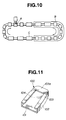
- a circulating loop is shown in FIG. 10.
- the carriage having a mold assembly mounted thereon is moved to a charging position A where a flexible polyurethane blow molding compound is supplied into the mold cavity, transferred to and passed through a heating furnace B where the molding compound is expanded and cured, and finally moved to an unloading position C where the molded foam part is taken out.
- the pressure regulator should also be mounted on each carriage and passed through the heating furnace. Then the carriage and circulating loop become complex.
- the pressure regulator such as a vacuum pump is exposed to high temperatures of 100 to 200°C, it can be damaged.
- the pressure regulator becomes compact and is mountable on the carriage without troubles. No damage occurs upon exposure to high temperature in the heating furnace.
- the mold assembly with the ejector/tank pressure regulator is compatible with the circulating race track loop so that synthetic resin foam parts can be effectively blow molded in vacuum. It is unnecessary to establish a high vacuum in the cavity. Since a subatmospheric pressure of about 460 to 660 mmHg is fully acceptable, the vacuum capability of an ejector is sufficient.
- the method for molding parts of expanded synthetic resin according to the invention is suited for the molding of parts of expanded synthetic resin having an open or closed-cell structure, typically parts of flexible polyurethane foam.
- the instant method is effective in the molding of automotive cushion pads such as bag-shaped seat back pads having a top pad portion 103a as shown in FIG. 11 and other automotive interior parts.
- the instant method is effective especially when molded parts are produced using a three or multi-sectional mold assembly.
- the preferred molding method involves feeding a synthetic resin blow molding compound into a mold cavity under atmospheric pressure, establishing a subatmospheric pressure in the mold cavity, causing the molding compound to expand in the cavity under the subatmospheric pressure, allowing the mold cavity to restore atmospheric pressure, opening the mold, and taking the molded part out of the mold.
- a mold assembly for use in such molding is generally designated at 1.
- the mold assembly has a three-sectional structure including a lower mold 2 having an upward open recess, an upper mold 3, and an insert 4.
- the upper mold 3 is removably mated with the lower mold 2 so as to close its open recess and define an enclosed space 5.
- the insert 4 is removably disposed in the enclosed space 5.
- the insert 4 on the upper surface is integrally formed with an upward extending, generally rectangular frame-shaped partition 6.
- the partition 6 includes a front portion 6a spaced a predetermined distance from the front end of the insert 4, a rear portion 6b positioned at the rear end of the insert 4, and side portions 6c positioned inward of the side edges of the insert 4.
- the partition 6 defines a chamber 7 between the upper surface of the insert 4 and the lower surface of the upper mold 3.
- the closed space 5 excluding the chamber 7 is a cavity 8 for molding.
- the cavity 8 includes a face portion-molding cavity 8a defined between the lower surface of the insert 4 and the upper surface of the lower mold 2, side portion-molding cavities 8b defined between the outer side surfaces of wedges 4a integrally formed with the side edges of the insert 4 and the inner side surface of the lower mold 2, and rear portion-molding cavities 8c, 8d defined between the upper surface of the insert 4 and the lower surface of the upper mold 3.
- the space defined between the upper surface of the insert 4 and the lower surface of the upper mold 3 and extending from the front end of the insert 4 to the partition front portion 6a is the cavity 8c for forming the top pad portion.
- the insert 4 is arranged for vertical motion in the closed space 5. That is, the insert 4 is held at a predetermined position by means of a pneumatic cylinder 9. Though not shown, the upper mold 3 is fixedly secured to a frame and the lower mold 2 is supported by contractible means such as an air bag so that the lower mold 2 may be set in place and separated from the upper mold 3.
- a gasket 10 is interposed at the parting line between the lower and upper molds 2 and 3. It is then possible to fasten the lower and upper molds 2 and 3 into air-tight engagement, preventing passage of air across the parting line.
- a gap 11 is left between the top of the partition 6 of the insert 4 and the lower surface of the upper mold 3.
- the gap 11 provides fluid communication between the chamber 7 and the cavity 8, allowing air to flow therebetween.
- the insert 4 on the upper surface is further provided with a separation wall 12 which surrounds the pneumatic cylinder 9.
- a gasket 13 is interposed between the top of the separation wall 12 and the lower surface of the upper mold 3 to prevent leakage of air from the pneumatic cylinder 9 into the chamber 7.
- a pressure regulator 21 includes a connector 23 fitted in the upper mold 3.
- the connector 23 has an air passage 22 in fluid communication with the chamber 7.
- the air passage 22 is connected to a release conduit 25 through a release valve 24 and a discharge conduit 27 through a discharge valve 26.
- the conduit 27 at the other end is coupled to a vacuum pump 28.
- the pressure regulator 21 further includes a controller 29 which delivers a first command to open the discharge valve 26, close the release valve 24, and actuate the vacuum pump 28 so that air in the chamber 7 is exhausted outside or a second command to close the discharge valve 26 and open the release valve 24, allowing the ambient air to flow into the chamber 7 through the release valve 24.
- a pressure sensor 30 connected to the controller 29 through a lead 31 is fitted in the upper mold 3 for detecting the pressure in the chamber 7.
- the controller 29 performs to actuate the vacuum pump 28 and change over the release and discharge valves 24 and 26. Accordingly, when the controller 29 delivers a first command to open the discharge valve 26, close the release valve 24, and actuate the vacuum pump 28, air in the chamber 7 is discharged to the outside so that the chamber 7 is kept under a subatmospheric pressure. At the same time, air from the cavity 8 is discharged through the gap 11 between the partition 6 of the insert 4 and the upper mold 3 and then through the chamber 7 so that the cavity 8 is also kept under a subatmospheric pressure. When the vacuum pump 28 is interrupted, the discharge valve 26 is closed, and the release valve 24 is opened, the atmospheric pressure will be restored in the chamber 7 and also in the cavity 8 through the gap 11.
- FIG. 11 Described below is the molding of a part as shown in FIG. 11 from flexible polyurethane foam using the above-mentioned mold assembly.
- the lower mold 2, upper mold 3 and insert 4 are roughly assembled as shown in FIGS. 1 and 2.
- a flexible polyurethane blow molding compound is introduced into the mold cavity.
- the upper mold 3 is mated with the lower mold 3.
- the mold assembly is tightly closed.
- the controller 29 delivers a first command to open the discharge valve 26, close the release valve 24, and actuate the vacuum pump 28. Then air in the chamber 7 is discharged outside and air in the cavity 8 is also discharged outside through the gap 11 and the chamber 7 so that the cavity 8 is kept under a subatmospheric pressure.
- the controller 29 delivers a command to control the vacuum pump 28, release valve 24, and discharge valve 26 so as to maintain the desired degree of vacuum. More particularly, if the pressure is higher than the target value, then the discharge valve 26 is opened to further discharge air outside. If the pressure is lower than the target value, then the release valve 24 is opened to supplement air.
- the controller 29 delivers a command to open the release valve 24 and close the discharge valve 26 whereby atmospheric pressure is restored in the chamber 7 and cavity 8.
- the upper mold 3 and insert 4 are detached from the lower mold 2. Since the upper mold 3 is detached from the lower mold 2 after the restoration of atmospheric pressure in the chamber 7 and cavity 8, mold separation can be done smoothly. If the vacuum is kept in the chamber 7 and cavity 8, it is difficult to remove the upper mold 3 from the lower mold 2.
- the cavity 8 is under subatmospheric pressure prior to blow molding.
- the pressure reduction from the atmospheric pressure is preferably 10 to 500 mmHg, more preferably 100 to 300 mmHg.
- the degree of lowering the density of foam depends on the magnitude of the subatmospheric pressure.
- the gap 11 between the upper mold 3 and the insert partition 6 is preferably 0.01 to 2 mm, more preferably 0.05 to 0.5 mm, most preferably 0.05 to 0.2 mm (applies generally).
- FIGS. 3 and 4 show a mold assembly for use in molding an automotive front cushion pad according to a second embodiment of the invention.
- This mold assembly 1 is substantially the same as the first embodiment of FIGS. 1 and 2 except that the cavity 8 is defined mostly between the lower mold 2 and the insert 4 and the rear portion-molding cavity 8c in FIG. 1 is omitted.
- the method of molding synthetic resin foam parts using this mold assembly is also the same as the first embodiment.
- like parts are designated by the same numerals as in FIGS. 1 and 2 and their description is omitted.
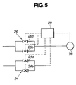
- FIG. 5 shows a variant of the first embodiment shown in FIGS. 1 and 2.
- the discharge valve 26 includes a first discharge valve 26a in the form of an electromagnetic valve having a large diameter air flowpath and a second discharge valve 26b in the form of an electromagnetic valve having a small diameter air flowpath which are connected in parallel in the discharge conduit 27.
- the first and second discharge valves 26a and 26b are coupled to the controller 29 so that their operation is controlled by a command from the controller 29 whereby air is passed through the first discharge valve 26a or the second discharge valve 26b.
- FIG. 1 shows a further preferred embodiment, as shown in FIG.
- the release valve 24 includes a first release valve 24a in the form of an electromagnetic valve having a large diameter air flowpath and a second release valve 24b in the form of an electromagnetic valve having a small diameter air flowpath which are connected in parallel in the release conduit 25.
- the first and second release valves 24a and 24b are coupled to the controller 29 so that their operation is controlled by a command from the controller 29 whereby air is passed through the first release valve 24a or the second release valve 24b.
- the lower mold 2, upper mold 3 and insert 4 are assembled in the same sequence as described in conjunction with FIGS. 1 and 2.
- a flexible polyurethane blow molding compound is introduced into the mold cavity.
- the mold assembly is tightly closed.
- the controller 29 delivers a command to close the release valve 24, open the large diameter discharge valve 26a of the discharge valve 26, and actuate the vacuum pump 28.
- air in the chamber 7 is discharged outside and air in the cavity 8 is also discharged outside through the gap 11 and the chamber 7 so that the cavity 8 is kept under a subatmospheric pressure.
- the controller 29 delivers a command to close the large diameter discharge valve 26a and open the small diameter discharge valve 26b so as to maintain the target subatmospheric pressure. More particularly, if the pressure is higher than the target value, then the small diameter discharge valve 26b is opened to discharge air from the chamber 7. If the pressure is lower than the target value, then the small diameter release valve 24b is opened to supplement air.
- the large diameter discharge valve is used when it is desired that the pressure in the chamber 7 reach the target value as fast as possible.
- the small diameter discharge and release valves are used when it is desired that air discharge or supplement is repeated in the vicinity of the target vacuum. If pressure control in the vicinity of the target vacuum is carried out only through the large diameter discharge valve, there would occur substantial pressure fluctuations. In an extreme case, such pressure fluctuations affect the surface of flexible polyurethane foam, resulting in irregular and collapsed cells.
- the large diameter discharge valve 26a is used until the target pressure is reached or approached so that the chamber 7 may be quickly evacuated. Once the target pressure is reached, the small diameter discharge valve 26b is used preferably in combination with the small diameter release valve 24b so that fine pressure adjustment is possible.
- Stable pressure control can be done in the vicinity of the target pressure, substantially avoiding cell collapse.
- the fine pressure control is advantageous particularly when blow molding is carried out in the cavity 8 under a subatmospheric pressure of lower than 560 mmHg, especially lower than 460 mmHg.
- the small diameter discharge valve 26b and release valve 24b are capable of pressure control with an error within ⁇ 5% or ⁇ 20 mmHg with respect to the target pressure.
- the large diameter discharge valve 26a and release valve 24a are given a tolerance of more than ⁇ 5% or ⁇ 20 mmHg with respect to the target pressure, for example, more than ⁇ 10% or ⁇ 30 mmHg with respect to the target pressure.
- the small diameter discharge valve 26b and release valve 24b preferably have a minimum diameter of 1 to 30 mm when they are open, and the large diameter discharge valve 26a and release valve 24a preferably have a minimum diameter of 10 to 50 mm when they are open.
- the valve size may be suitably selected since it varies with the mold cavity volume, chamber volume, seal tightness and vacuum pump capacity.
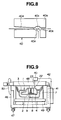
- FIGS. 6 to 9 illustrates a third embodiment of the invention.
- This embodiment is substantially the same as the first embodiment of FIGS. 1 and 2 except that a pressure regulator 45 including an ejector or vacuum generator 40 and an air tank 41 is used.
- the ejector 40 includes an ejector body 40a, a compressed air flowpath 40b and a discharge path 40d defined in the ejector body 40a in alignment, a nozzle 40c disposed between the flowpath 40b and discharge path 40d, and a suction branch 40e in communication with the jet outlet of the nozzle 40c.
- the discharge path 40d is divergent or increases its diameter from the inner end to the outer end and serves as a diffuser.
- the compressed air flowpath 40b of the ejector 40 is connected to a compressed air outlet 41a of the air tank 41 full of compressed air through a conduit 42.
- the suction branch 40e is connected to the air passage 22 of the connector 23 in fluid communication with the chamber 7.
- the compressed air in the air tank 41 is introduced into the flowpath 40b of the ejector 40, ejected from the nozzle 40c as a jet, and discharged outside through the discharge path 40d while reducing the pressure.
- air in the suction branch 40e is sucked by and discharged with the compressed air flow through the discharge path 40d from the air tank 41.
- the mold assembly according to the third embodiment of the invention is mounted on a carriage 46.
- the carriage 46 is equipped with tire wheels 47 for free travel and travels along a circulating race track line as shown in FIG. 10.
- the upper mold 3 is fixedly secured to a frame 48. Contractible air bags 49 are rested on the carriage 46 to support the lower mold 2. When the air bags 49 are contracted, the lower mold 2 is separated from the upper mold 3 so that the mold assembly 1 is open and chargeable with a blow molding compound. When the air bags 49 are inflated, the lower mold 2 is lifted to tightly engage with the upper mold 3. 50 is a clamp.
- the carriage 46 After exiting the furnace B, the carriage 46 reaches an unloading position C. At this point, the supply of compressed air from the air tank 41 to the ejector 40 is interrupted. Then atmospheric pressure is restored in the chamber 7 and cavity 8. The restoration of atmospheric pressure in the chamber 7 and cavity 8 allows the upper mold 3 to be removed from the lower mold 2. After the upper mold 3 and insert 4 are removed from the lower mold 2, the molded part is taken out. The process is repeated along the path shown in FIG. 10.
- the vacuum pump used was a dry pump having a discharge capacity of 235 liter/min. (KRX-3SS manufactured by Orion K.K.).
- the discharge and release valves used were high vacuum electromagnetic valves having a permissible pressure range of 10 -8 Torr to 2 kgf/cm 2 (HVB type manufactured by CKD).
- the pressure sensor used was a pressure transmitter having a sensitive pressure range of -0.5 to 0.5 kgf/cm 2 (KH25 manufactured by Nagano Instrument K.K.).
- the gap 11 was about 0.1 mm.
- the mold cavity had a volume of 28.7 liters.
- the polyurethane blow molding compound used was a back pad-forming versatile HR foam formulation commercially available from Bridgestone Corp. This formulation produces a foam having a density of 0.035 g/cm 3 when it is allowed to expand freely without using a mold.
- An automotive front cushion pad was molded using the mold assembly shown in FIGS. 3 and 4.
- the vacuum pump, discharge valve, release valve, and pressure sensor used were the same as in Example 1.
- the gap 11 between the upper mold 3 and the insert 4 was about 0.1 mm over the entire periphery.
- the mold cavity had a volume of 28 liters.
- the polyurethane blow molding compound used was a cushion-forming high restitution foam formulation commercially available from Bridgestone Corp. This formulation produces a foam having a density of 0.042 g/cm 3 when it is allowed to expand free without using a mold.
- the vacuum pump used was a pump having a discharge capacity of 300 liter/min.
- the large diameter discharge and release valves used were high vacuum electromagnetic valves having an air flowpath with a minimum diameter of 22 mm.
- the small diameter discharge and release valves used were high vacuum electromagnetic valves having an air flowpath with a minimum diameter of 9 mm or 5 mm.
- the pressure sensor used was a pressure transmitter having a sensitive pressure range of -0.5 to 0.5 kgf/cm 2 (KH25 manufactured by Nagano Instrument K.K.).
- the gap 11 was about 0.1 mm.
- the mold cavity had a volume of 28.7 liters.
- the polyurethane blow molding compound used was a back pad-forming versatile HR foam formulation commercially available from Bridgestone Corp. (see Example 1).
- the molding compound was introduced into the mold cavity, and the cavity pressure was then reduced by 300 mmHg.
- the compound was expanded and molded in the cavity while the mold cavity was kept under vacuum.
- the pressure in the chamber was controlled so as to keep the pressure reduction of 300 mmHg.
- pressure fluctuations of ⁇ 25 mmHg ( ⁇ 8.5%) with respect to the target pressure occurred.
- the resulting foam part had collapsed cells on its surface.
- the chamber was evacuated to reduce the pressure by 300 mmHg. Thereafter, using the small diameter discharge valve and release valve having an open diameter of 9 mm, the pressure in the chamber was controlled so as to keep the pressure reduction of 300 mmHg. Pressure fluctuations were only ⁇ 10 mmHg ( ⁇ 3%) with respect to the target pressure. When the small diameter discharge valve and release valve having an open diameter of 5 mm were used for pressure control, pressure fluctuations were only ⁇ 5 mmHg ( ⁇ 1.5%) with respect to the target pressure.
- the resulting foam parts had no collapsed cells on its surface and a good outer appearance.
- the resulting foam part had a density of 0.032 g/cm 3 and no burrs at all.
- An automotive front back pad was molded by using a mold assembly as shown in FIGS. 6 to 8, mounting it on a carriage as shown in FIG. 9, and circulating it along a circulating line as shown in FIG. 10.
- the ejector used was an ejector model YPA08QR manufactured by CKD.
- the ejector was operated under conditions including a supply air pressure of 2 kgf/cm 2 , an air consumption amount of 20 liter/min., an operating time of 1-1/2 minutes, and an ultimate pressure reduction of 200 mmHg.
- the air tank was filled with 50 liters of air and 30 liters of air was used.
- the gap 11 was about 0.1 mm.
- the mold cavity had a volume of 25 liters.
- the polyurethane blow molding compound used was a back pad-forming versatile HR foam formulation commercially available from Bridgestone Corp. (see Example 1).
- the molding compound 900 grams, was introduced into the mold cavity. By operating the ejector, the cavity pressure was then reduced by 200 mmHg. The compound was expanded and molded in the cavity while the mold cavity was kept under the subatmospheric pressure. The resulting foam part had a density of 0.034 g/cm 3 and no burrs at all.
Landscapes
- Engineering & Computer Science (AREA)
- Mechanical Engineering (AREA)
- Moulds For Moulding Plastics Or The Like (AREA)
- Casting Or Compression Moulding Of Plastics Or The Like (AREA)
Description
- This invention relates to molding apparatus for use in the molding of parts of expanded synthetic resin, preferably having an open cell structure, typically parts of flexible polyurethane foam. It also relates to a method for molding such parts using the apparatus.
- Automotive seat back pads are conventionally formed of flexible polyurethane foam. One exemplary pad is shown in FIG. 11. The
pad 100 has a face portion 101, aside portion 102, and aback portion 103 which are integrally molded. Theback portion 103 is formed with anopening 104 so that theback portion 103 is of an inverted U shape. Thus thepad 100 as a whole has a pocket or curved channel shape. When it is desired to mold such a pocket shapedpad 100, amold assembly 51 as shown in FIGS. 12 and 13 is used in the prior art. More particularly, themold assembly 51 is a three-sectional mold assembly consisting of alower mold 52, anupper mold 53, and aninsert 54. Thelower mold 52 and theinsert 54 definetherebetween cavities upper mold 53 andinsert 54 definetherebetween cavities cavities - Several problems arise in molding a pad as shown in FIG. 11. In order to mold an upper part 103a of the
back portion 103 of thepad 100, generally known as a top pad part, thecavity 56a for forming the top pad part must be entirely filled with the molding compound, to its deepest point. To this end, it is a common practice to introduce the molding compound into thecavities more burrs 106 are formed on themolded part 105 at the mold split positions or parting lines as shown in FIG. 14. After removal from the mold, an extra step is needed for deburring, tailoring and finishing. - In conjunction with the molding of automotive interior parts such as cushion pads from a polyurethane blow molding compound, a method for controlling the pressure in the mold cavity is proposed in JP-A-UM-60418/1983 and JP-A-58/067427. In this method, the mold cavity is defined between a lower mold and an insert. An upper shell is attached so as to cover the lower mold and the insert and define a pressure regulating chamber between the insert and the upper mold. The insert is provided with a vent hole for providing fluid communication between the chamber and the mold cavity. Then air in the cavity is discharged into the chamber through the vent hole.
- Although this method uses the lower mold, insert and upper shell the cavity for molding a part is defined by the lower mold and the insert. Therefore, the molded part is produced using only the lower mold and the insert while the upper shell only serves to define the pressure regulating chamber with the insert. In an essential sense, therefore, this mold assembly is a two-sectional mold rather than a three-sectional mold, and cannot produce a pocketed part having a top pad portion 103a as shown in FIG. 11. It is still necessary to use a three-sectional mold as shown in FIGS. 12 and 13 when it is desired to mold such a part, or other undercut parts.
- The apparatus of Japanese U.M. Application 60418/1983 also suffers from an increased rate of rejection in molding pads of relatively simple shape because air voids are formed near the parting line. Since regulation of the pressure between the cavity and the chamber is performed by way of vent holes, the vent holes must be increased in size or number. Then air is locally exhausted to disorder the expansion balance of foam. It is cumbersome to trim off burrs formed in the vent hole(s) at the end of molding.
- EP-A-461522 (and JP-A-4/226313) discloses a method for molding a polyurethane foam part comprising the steps of reducing the gas pressure in a mold cavity, introducing into the mold cavity a polyurethane stock in the form of a mixture of 100 parts by weight of a polyol component and 0.1 to 0.6 part by weight of water as a blowing agent, and expanding the stock to flow in and fill the cavity. In this method, however, the gas pressure in the mold cavity is reduced by evacuating the cavity through a gap at the parting plane between two mold sections. The periphery of the mold along the parting plane is surrounded by a closed chamber which is evacuated to exhaust air from the cavity through the gap between the parting planes. Burrs or fins are often formed in the gap between the parting planes.
- A general aim herein is to provide new and useful apparatus and methods for moulding expanded synthetic foam.
- One preferred aim is to provide an apparatus and method for effectively molding a synthetic resin foam part such as automotive cushion pads (e.g., seat back pads) and automotive interior parts at a high blowing magnification to a low density in high yields while minimizing burr formation.
- In a first aspect, the present invention provides molding apparatus for making a synthetic resin foam part comprising
- a mold assembly having a lower mold defining an upwardly-opening recess and an upper mold removably attachable over the lower mold to define an enclosed space providing a molding cavity into which synthetic resin blow molding compound is introduced in use, and
- pressure regulator means connected to exhaust air from a chamber which communicates with the molding cavity, so as to create sub-atmospheric pressure in said chamber and thereby exhaust air from the molding cavity; characterised in that
- the mold assembly comprises an insert removably disposed in the enclosed space between the upper and lower molds to define said chamber in the enclosed space between the upper surface of the insert and the upper mold and to divide the chamber from the molding cavity, and in that the insert has an upwardly-directed partition which opposes the lower surface of the upper mold across a gap providing said pressure regulation communication between the chamber and molding cavity.
-
- The gap between the insert's upwardly directed partition and the upper mold preferably extends around or is distributed around at least most of and preferably all of the peripheral boundary of the partition. Preferably it is continuous. It may be of substantially uniform width. Preferred width ranges are stated below. Alignment structure may be provided between the upper mold and insert, preferably inwardly of the gap, to align those parts such that the gap is maintained.
- The pressure regulator means may be adjustable in flow rate, e.g. to enable slow adjustment (suitable to maintain a desired pressure already reached) or fast adjustment (suitable for initial approach to a desired pressure). Adjustment may be discontinuous, e.g. between large and small diameter valves as mentioned below.
- A preferred pressure-reducing pump is an ejector pump driven by compressed air, for reasons explained below.
- The insert may have one or more moulding surfaces projecting transversely (relative to the mould-opening direction) beyond its partition, to overlap the upper mould and enable the moulding of re-entrant surfaces such as the seat pad back parts described above.
- Preferably, the pressure regulator means includes means for supplying air into the subatmospheric chamber to restore atmospheric pressure in the chamber whereby air is also supplied to the cavity through the gap when air is supplied into the chamber.
- Preferably, the synthetic resin foam part is a flexible polyurethane foam part.
- The mold apparatus is preferably adapted for molding an automotive seat pad of flexible polyurethane foam wherein the insert partition has a front portion spaced from a front end of the insert wherein a top pad-molding cavity is defined between the upper surface of the insert and the upper mold and between the front end of the insert and the front portion of the insert partition.
- Preferably, the pressure regulator means includes a discharge conduit having one end connected to the chamber and another end connected to a vacuum pump, and parallel large and small diameter discharge valves inserted in the discharge conduit in a switchable relationship so that either one of the large and small diameter discharge valves may be selected. Air in the chamber is exhausted through the large diameter discharge valve until nearly the subatmospheric pressure is established in the chamber, and thereafter switching is made to select the small diameter discharge valve for further continuing air exhaustion.
- Preferably, the pressure regulator means includes an ejector and an air tank filled with compressed air. The ejector includes a flowpath connected to the air tank, a nozzle at an outlet of the flowpath for ejecting compressed air incoming from the tank through the flowpath, a discharge flowpath for discharging compressed air ejected from the nozzle, and a suction branch in fluid communication with a position where compressed air is ejected from the nozzle, and the suction branch is connected to the chamber in the mold assembly. Compressed air in the air tank is ejected from the nozzle to form a jet by which air in the suction branch is exhausted and discharged through the discharge flowpath, whereby the chamber in the mold assembly in communication with the suction branch is evacuated.
- In one preferred embodiment, the mold apparatus is mounted on a movable carriage wherein the carriage travels through a heating furnace while the mold cavity is kept in the subatmospheric pressure.
- In a second aspect of the present invention as set out in
claim 11 there is provided a method for molding a synthetic resin foam part using the mold apparatus of the first aspect, comprising the steps of: - feeding a synthetic resin blow molding compound into the cavity under atmospheric pressure,
- tightly closing the mold assembly,
- actuating the pressure regulator means to exhaust air in the chamber and air in the cavity through the gap to establish a subatmospheric pressure in the cavity, and
- causing the molding compound to be blow molded.
-
- Preferably, the method further comprising the steps of:
- introducing air into the subatmospheric chamber to restore atmospheric pressure in the chamber at the end of blow molding, thereby introducing air into the cavity through the gap to restore atmospheric pressure in the cavity,
- detaching the upper mold and the insert from the lower mold, and
- taking out the molded foam part.
-
- Preferably, the synthetic resin foam part is a flexible polyurethane foam part.
- The method is preferably adapted for molding an automotive seat pad of flexible polyurethane foam wherein the insert partition has a front portion spaced from a front end of the insert wherein a top pad-molding cavity is defined between the upper surface of the insert and the upper mold and between the front end of the insert and the front portion of the insert partition.
- Preferably, the step of exhausting air in the chamber and air in the cavity through the gap to establish a subatmospheric pressure in the cavity includes two stages of quickly exhausting air in the chamber until the chamber reaches near the target subatmospheric pressure and thereafter effecting fine pressure control so as to establish and keep the target subatmospheric pressure in the chamber.
- In one preferred embodiment wherein the pressure regulator means comprises an ejector and an air tank for feeding compressed air to the ejector, and the ejector has a suction branch connected to the chamber in the mold assembly, the step of actuating the pressure regulator means to exhaust air in the chamber and air in the cavity through the gap to establish a subatmospheric pressure in the cavity includes ejecting compressed air from the ejector to form a jet by which air in the suction branch is exhausted to evacuate the chamber in the mold assembly in communication with the suction branch.
- In a further preferred embodiment, the method further comprises the steps of: mounting the mold apparatus on a movable carriage, moving the carriage to a loading position where a synthetic resin blow molding compound is fed into the cavity under atmospheric pressure, moving the carriage through a heating furnace, thereby causing the molding compound to be blow molded under subatmospheric pressure, and finally moving the carriage to an unloading position where the molded foam part is taken out of the mold assembly.
- In the molding apparatus and method of the invention, the mold cavity is charged with the synthetic resin blow molding compound and then evacuated to vacuum before the molding compound is expanded and molded under vacuum. By virtue of an increased blowing magnification,
the least necessary amount of molding compound may be fed into the cavity and molded into a foam part having a lower density. Since the mold cavity is under a negative pressure, formation of burrs or fins is minimized. Using a mold assembly comprising a lower mold, insert and upper mold, any parts of complex shape such as automotive seat pads as shown in FIG. 11 can be produced in high yields to a lighter weight than conventionally molded parts. Formation of burrs is reduced or eliminated. Trimming and finishing steps are significantly mitigated. The drawbacks of the apparatus of Japanese U.M. Application 60418/1983 may be eliminated. The technique is advantageous particularly when foam parts having an open-cell structure, typically flexible polyurethane foam parts or foam parts having a closed-cell structure (whose cells are subsequently crushed into open cells if necessary) are molded. - After blow molding, the chamber and cavity which have been in subatmospheric pressure are relieved to restore atmospheric pressure and thereafter, the upper mold and insert are detached from the lower mold and the molded part is taken out. The restoration of atmospheric pressure allow for easy removal of the upper mold and insert from the lower mold. The mold removal step is very smooth. If the chamber and cavity are kept in vacuum, it requires a very strong force to detach the upper mold and insert from the lower mold. Beyond a certain degree of vacuum, the mold assembly cannot be opened. In our preferred procedure, the mold assembly can be smoothly opened since the pressure difference between the chamber and the ambient atmosphere is eliminated before mold opening.
- In evacuating the cavity, evacuation may be through a large diameter discharge valve until the target subatmospheric pressure (or vacuum) is reached or approached. Then, the valve mechanism is changed over to a small diameter discharge valve, through which fine pressure control is carried out to establish the target subatmospheric pressure. This minimizes the fluctuation of reduced pressure across the target value to ensure production of foam parts having a satisfactory surface state without irregular and collapsed cells.
- In one embodiment, the vacuum blow molding process is carried out in a stationary mold apparatus. In another embodiment, the vacuum blow molding process is carried out in a small scale circular line (known as a turn table) along which about ten carriages having mold assemblies mounted thereon travel. In a further embodiment, the vacuum blow molding process is carried out in a large scale circulating line (known as a race track line) along which about two scores of carriages having mold assemblies mounted thereon travel. In the last embodiment, it is preferred to use an ejector and an air tank as the pressure regulator.
- In general, automotive seat cushion pads of flexible polyurethane foam are produced by circulating carriages each having a mold assembly mounted thereon along a closed loop. Such a circulating loop is shown in FIG. 10. The carriage having a mold assembly mounted thereon is moved to a charging position A where a flexible polyurethane blow molding compound is supplied into the mold cavity, transferred to and passed through a heating furnace B where the molding compound is expanded and cured, and finally moved to an unloading position C where the molded foam part is taken out. When the vacuum blow molding process is carried out along the circulating race track loop, the pressure regulator should also be mounted on each carriage and passed through the heating furnace. Then the carriage and circulating loop become complex. If the pressure regulator such as a vacuum pump is exposed to high temperatures of 100 to 200°C, it can be damaged. In contrast, when an ejector and an air tank are used as the pressure regulator, the pressure regulator becomes compact and is mountable on the carriage without troubles. No damage occurs upon exposure to high temperature in the heating furnace. Then the mold assembly with the ejector/tank pressure regulator is compatible with the circulating race track loop so that synthetic resin foam parts can be effectively blow molded in vacuum. It is unnecessary to establish a high vacuum in the cavity. Since a subatmospheric pressure of about 460 to 660 mmHg is fully acceptable, the vacuum capability of an ejector is sufficient.
- These and further features of the present invention will be apparent with reference to the following description and drawings, wherein:
- FIG. 1 is a schematic cross-sectional view in one direction of a mold assembly for a front back pad according to one embodiment of the invention.
- FIG. 2 is a schematic cross-sectional view in a perpendicular direction of the same mold assembly as in FIG. 1.
- FIG. 3 is a schematic cross-sectional view in one direction of a mold assembly for a front cushion pad according to another embodiment of the invention.
- FIG. 4 is a schematic cross-sectional view in a perpendicular direction of the same mold assembly as in FIG. 3.
- FIG. 5 is a block diagram of the arrangement of discharge and release valves used in the front back pad mold assembly according to a further embodiment.
- FIG. 6 is a schematic cross-sectional view in one direction of a mold assembly for a front back pad according to a still further embodiment of the invention.
- FIG. 7 is a schematic cross-sectional view in a perpendicular direction of the same mold as in FIG. 6.
- FIG. 8 is a schematic cross-sectional view of an ejector.
- FIG. 9 is a partially cut-away, side elevation of a carriage on which the mold assembly is mounted.
- FIG. 10 is a schematic view of a circulating line.
- FIG. 11 is a perspective view showing one exemplary front back pad.
- FIG. 12 is a schematic cross-sectional view in one direction of a prior art mold for a front back pad.
- FIG. 13 is a schematic cross-sectional view in a perpendicular direction of the prior art mold.
- FIG. 14 is schematic illustration of a urethane foam part obtained using the mold of FIGS. 12 and 13, showing burrs thereon.
-
- The method for molding parts of expanded synthetic resin according to the invention is suited for the molding of parts of expanded synthetic resin having an open or closed-cell structure, typically parts of flexible polyurethane foam. The instant method is effective in the molding of automotive cushion pads such as bag-shaped seat back pads having a top pad portion 103a as shown in FIG. 11 and other automotive interior parts. The instant method is effective especially when molded parts are produced using a three or multi-sectional mold assembly.
- The preferred molding method involves feeding a synthetic resin blow molding compound into a mold cavity under atmospheric pressure, establishing a subatmospheric pressure in the mold cavity, causing the molding compound to expand in the cavity under the subatmospheric pressure, allowing the mold cavity to restore atmospheric pressure, opening the mold, and taking the molded part out of the mold.
- It is described how to mold a pocketed seat back pad as shown in FIG. 11. Referring to FIGS. 1 and 2, a mold assembly for use in such molding according to a first embodiment of the invention is generally designated at 1. For brevity's sake, the terms "upper" and "lower" are used as viewed in FIGS. 1 and 2 and the term "front" and "rear" correspond to the left and right as viewed in FIG. 1. The mold assembly has a three-sectional structure including a
lower mold 2 having an upward open recess, anupper mold 3, and aninsert 4. Theupper mold 3 is removably mated with thelower mold 2 so as to close its open recess and define anenclosed space 5. Theinsert 4 is removably disposed in theenclosed space 5. - The
insert 4 on the upper surface is integrally formed with an upward extending, generally rectangular frame-shapedpartition 6. Thepartition 6 includes afront portion 6a spaced a predetermined distance from the front end of theinsert 4, arear portion 6b positioned at the rear end of theinsert 4, andside portions 6c positioned inward of the side edges of theinsert 4. Thepartition 6 defines achamber 7 between the upper surface of theinsert 4 and the lower surface of theupper mold 3. Theclosed space 5 excluding thechamber 7 is acavity 8 for molding. More particularly, thecavity 8 includes a face portion-molding cavity 8a defined between the lower surface of theinsert 4 and the upper surface of thelower mold 2, side portion-molding cavities 8b defined between the outer side surfaces of wedges 4a integrally formed with the side edges of theinsert 4 and the inner side surface of thelower mold 2, and rear portion-molding cavities insert 4 and the lower surface of theupper mold 3. The space defined between the upper surface of theinsert 4 and the lower surface of theupper mold 3 and extending from the front end of theinsert 4 to thepartition front portion 6a is thecavity 8c for forming the top pad portion. - The
insert 4 is arranged for vertical motion in theclosed space 5. That is, theinsert 4 is held at a predetermined position by means of apneumatic cylinder 9. Though not shown, theupper mold 3 is fixedly secured to a frame and thelower mold 2 is supported by contractible means such as an air bag so that thelower mold 2 may be set in place and separated from theupper mold 3. - A
gasket 10 is interposed at the parting line between the lower andupper molds upper molds - When the
upper mold 3 andinsert 4 are set relative to thelower mold 2 as shown in FIG. 1, agap 11 is left between the top of thepartition 6 of theinsert 4 and the lower surface of theupper mold 3. Thegap 11 provides fluid communication between thechamber 7 and thecavity 8, allowing air to flow therebetween. - The
insert 4 on the upper surface is further provided with aseparation wall 12 which surrounds thepneumatic cylinder 9. Agasket 13 is interposed between the top of theseparation wall 12 and the lower surface of theupper mold 3 to prevent leakage of air from thepneumatic cylinder 9 into thechamber 7. - A
pressure regulator 21 includes aconnector 23 fitted in theupper mold 3. Theconnector 23 has anair passage 22 in fluid communication with thechamber 7. Theair passage 22 is connected to arelease conduit 25 through arelease valve 24 and adischarge conduit 27 through adischarge valve 26. Theconduit 27 at the other end is coupled to avacuum pump 28. Thepressure regulator 21 further includes acontroller 29 which delivers a first command to open thedischarge valve 26, close therelease valve 24, and actuate thevacuum pump 28 so that air in thechamber 7 is exhausted outside or a second command to close thedischarge valve 26 and open therelease valve 24, allowing the ambient air to flow into thechamber 7 through therelease valve 24. Apressure sensor 30 connected to thecontroller 29 through a lead 31 is fitted in theupper mold 3 for detecting the pressure in thechamber 7. In response to a detection signal from thepressure sensor 30, thecontroller 29 performs to actuate thevacuum pump 28 and change over the release and dischargevalves controller 29 delivers a first command to open thedischarge valve 26, close therelease valve 24, and actuate thevacuum pump 28, air in thechamber 7 is discharged to the outside so that thechamber 7 is kept under a subatmospheric pressure. At the same time, air from thecavity 8 is discharged through thegap 11 between thepartition 6 of theinsert 4 and theupper mold 3 and then through thechamber 7 so that thecavity 8 is also kept under a subatmospheric pressure. When thevacuum pump 28 is interrupted, thedischarge valve 26 is closed, and therelease valve 24 is opened, the atmospheric pressure will be restored in thechamber 7 and also in thecavity 8 through thegap 11. - Described below is the molding of a part as shown in FIG. 11 from flexible polyurethane foam using the above-mentioned mold assembly. The
lower mold 2,upper mold 3 andinsert 4 are roughly assembled as shown in FIGS. 1 and 2. A flexible polyurethane blow molding compound is introduced into the mold cavity. Theupper mold 3 is mated with thelower mold 3. The mold assembly is tightly closed. Thecontroller 29 delivers a first command to open thedischarge valve 26, close therelease valve 24, and actuate thevacuum pump 28. Then air in thechamber 7 is discharged outside and air in thecavity 8 is also discharged outside through thegap 11 and thechamber 7 so that thecavity 8 is kept under a subatmospheric pressure. When thepressure sensor 30 detects that the predetermined degree of vacuum is reached in thechamber 7, thecontroller 29 delivers a command to control thevacuum pump 28,release valve 24, and dischargevalve 26 so as to maintain the desired degree of vacuum. More particularly, if the pressure is higher than the target value, then thedischarge valve 26 is opened to further discharge air outside. If the pressure is lower than the target value, then therelease valve 24 is opened to supplement air. - Under the thus established vacuum, the molding compound is expanded and molded. Thereafter, the
controller 29 delivers a command to open therelease valve 24 and close thedischarge valve 26 whereby atmospheric pressure is restored in thechamber 7 andcavity 8. In this state, theupper mold 3 andinsert 4 are detached from thelower mold 2. Since theupper mold 3 is detached from thelower mold 2 after the restoration of atmospheric pressure in thechamber 7 andcavity 8, mold separation can be done smoothly. If the vacuum is kept in thechamber 7 andcavity 8, it is difficult to remove theupper mold 3 from thelower mold 2. - After the
upper mold 3 andinsert 4 are detached from thelower mold 2 in this way, the molded part is taken out. - The
cavity 8 is under subatmospheric pressure prior to blow molding. The pressure reduction from the atmospheric pressure is preferably 10 to 500 mmHg, more preferably 100 to 300 mmHg. The degree of lowering the density of foam depends on the magnitude of the subatmospheric pressure. - The
gap 11 between theupper mold 3 and theinsert partition 6 is preferably 0.01 to 2 mm, more preferably 0.05 to 0.5 mm, most preferably 0.05 to 0.2 mm (applies generally). - FIGS. 3 and 4 show a mold assembly for use in molding an automotive front cushion pad according to a second embodiment of the invention. This
mold assembly 1 is substantially the same as the first embodiment of FIGS. 1 and 2 except that thecavity 8 is defined mostly between thelower mold 2 and theinsert 4 and the rear portion-molding cavity 8c in FIG. 1 is omitted. The method of molding synthetic resin foam parts using this mold assembly is also the same as the first embodiment. In FIGS. 3 and 4, like parts are designated by the same numerals as in FIGS. 1 and 2 and their description is omitted. - FIG. 5 shows a variant of the first embodiment shown in FIGS. 1 and 2. The
discharge valve 26 includes afirst discharge valve 26a in the form of an electromagnetic valve having a large diameter air flowpath and asecond discharge valve 26b in the form of an electromagnetic valve having a small diameter air flowpath which are connected in parallel in thedischarge conduit 27. The first andsecond discharge valves controller 29 so that their operation is controlled by a command from thecontroller 29 whereby air is passed through thefirst discharge valve 26a or thesecond discharge valve 26b. In a further preferred embodiment, as shown in FIG. 5, therelease valve 24 includes afirst release valve 24a in the form of an electromagnetic valve having a large diameter air flowpath and asecond release valve 24b in the form of an electromagnetic valve having a small diameter air flowpath which are connected in parallel in therelease conduit 25. The first andsecond release valves controller 29 so that their operation is controlled by a command from thecontroller 29 whereby air is passed through thefirst release valve 24a or thesecond release valve 24b. - When a part as shown in FIG. 11 is molded from flexible polyurethane foam using the above-mentioned mold assembly, the
lower mold 2,upper mold 3 andinsert 4 are assembled in the same sequence as described in conjunction with FIGS. 1 and 2. A flexible polyurethane blow molding compound is introduced into the mold cavity. The mold assembly is tightly closed. Thecontroller 29 delivers a command to close therelease valve 24, open the largediameter discharge valve 26a of thedischarge valve 26, and actuate thevacuum pump 28. Then air in thechamber 7 is discharged outside and air in thecavity 8 is also discharged outside through thegap 11 and thechamber 7 so that thecavity 8 is kept under a subatmospheric pressure. When thepressure sensor 30 detects that the predetermined degree of vacuum is reached in thechamber 7, thecontroller 29 delivers a command to close the largediameter discharge valve 26a and open the smalldiameter discharge valve 26b so as to maintain the target subatmospheric pressure. More particularly, if the pressure is higher than the target value, then the smalldiameter discharge valve 26b is opened to discharge air from thechamber 7. If the pressure is lower than the target value, then the smalldiameter release valve 24b is opened to supplement air. - The large diameter discharge valve is used when it is desired that the pressure in the
chamber 7 reach the target value as fast as possible. The small diameter discharge and release valves are used when it is desired that air discharge or supplement is repeated in the vicinity of the target vacuum. If pressure control in the vicinity of the target vacuum is carried out only through the large diameter discharge valve, there would occur substantial pressure fluctuations. In an extreme case, such pressure fluctuations affect the surface of flexible polyurethane foam, resulting in irregular and collapsed cells. In the preferred embodiment shown in FIG. 5, the largediameter discharge valve 26a is used until the target pressure is reached or approached so that thechamber 7 may be quickly evacuated. Once the target pressure is reached, the smalldiameter discharge valve 26b is used preferably in combination with the smalldiameter release valve 24b so that fine pressure adjustment is possible. Stable pressure control can be done in the vicinity of the target pressure, substantially avoiding cell collapse. The fine pressure control is advantageous particularly when blow molding is carried out in thecavity 8 under a subatmospheric pressure of lower than 560 mmHg, especially lower than 460 mmHg. The smalldiameter discharge valve 26b andrelease valve 24b are capable of pressure control with an error within ±5% or ±20 mmHg with respect to the target pressure. In contrast, the largediameter discharge valve 26a andrelease valve 24a are given a tolerance of more than ±5% or ±20 mmHg with respect to the target pressure, for example, more than ±10% or ±30 mmHg with respect to the target pressure. In this regard, the smalldiameter discharge valve 26b andrelease valve 24b preferably have a minimum diameter of 1 to 30 mm when they are open, and the largediameter discharge valve 26a andrelease valve 24a preferably have a minimum diameter of 10 to 50 mm when they are open. The valve size may be suitably selected since it varies with the mold cavity volume, chamber volume, seal tightness and vacuum pump capacity. - FIGS. 6 to 9 illustrates a third embodiment of the invention. This embodiment is substantially the same as the first embodiment of FIGS. 1 and 2 except that a
pressure regulator 45 including an ejector orvacuum generator 40 and anair tank 41 is used. As shown in FIG. 8, theejector 40 includes anejector body 40a, acompressed air flowpath 40b and adischarge path 40d defined in theejector body 40a in alignment, anozzle 40c disposed between the flowpath 40b anddischarge path 40d, and asuction branch 40e in communication with the jet outlet of thenozzle 40c. Thedischarge path 40d is divergent or increases its diameter from the inner end to the outer end and serves as a diffuser. Thecompressed air flowpath 40b of theejector 40 is connected to a compressed air outlet 41a of theair tank 41 full of compressed air through aconduit 42. Thesuction branch 40e is connected to theair passage 22 of theconnector 23 in fluid communication with thechamber 7. On use, the compressed air in theair tank 41 is introduced into the flowpath 40b of theejector 40, ejected from thenozzle 40c as a jet, and discharged outside through thedischarge path 40d while reducing the pressure. At the same time, air in thesuction branch 40e is sucked by and discharged with the compressed air flow through thedischarge path 40d from theair tank 41. Then air in thechamber 7 in fluid communication with thebranch 40e and air in thecavity 8 which is in fluid communication with thechamber 7 through thegap 11 are sucked. As a result, thechamber 7 andcavity 8 are kept in vacuum. When air supply from theair tank 41 is interrupted, ambient air will flow from the outside into thedischarge path 40d and then into thechamber 7 andcavity 8 through thebranch 40e. Atmospheric pressure is restored in thechamber 7 andcavity 8 in this way. - As shown in FIG. 9, the mold assembly according to the third embodiment of the invention is mounted on a
carriage 46. Thecarriage 46 is equipped withtire wheels 47 for free travel and travels along a circulating race track line as shown in FIG. 10. - In FIG. 9, the
upper mold 3 is fixedly secured to aframe 48.Contractible air bags 49 are rested on thecarriage 46 to support thelower mold 2. When theair bags 49 are contracted, thelower mold 2 is separated from theupper mold 3 so that themold assembly 1 is open and chargeable with a blow molding compound. When theair bags 49 are inflated, thelower mold 2 is lifted to tightly engage with theupper mold 3. 50 is a clamp. - When a part of flexible polyurethane foam as shown in FIG. 11 is molded in the
mold assembly 1 mounted on thecarriage 46, thelower mold 2,upper mold 3 andinsert 4 are loosely set as shown in FIGS. 6 and 7. Thecarriage 46 is moved to a charging position A (see FIG. 10) where a flexible polyurethane foam blowing compound is supplied into the mold cavity. The mold assembly is tightly closed. Then compressed air is introduced from theair tank 41 into theejector 40 to keep thechamber 7 and hence, thecavity 8 of the mold assembly in a subatmospheric pressure. The compound is then expanded and molded. Thecarriage 46 enters a heating furnace B and advances therethrough while the expanded part is cured under the subatmospheric pressure. After exiting the furnace B, thecarriage 46 reaches an unloading position C. At this point, the supply of compressed air from theair tank 41 to theejector 40 is interrupted. Then atmospheric pressure is restored in thechamber 7 andcavity 8. The restoration of atmospheric pressure in thechamber 7 andcavity 8 allows theupper mold 3 to be removed from thelower mold 2. After theupper mold 3 andinsert 4 are removed from thelower mold 2, the molded part is taken out. The process is repeated along the path shown in FIG. 10. - Examples of the present invention are given below by way of illustration and not by way of limitation.
- An automotive front back pad was molded using the mold assembly shown in FIGS. 1 and 2. The vacuum pump used was a dry pump having a discharge capacity of 235 liter/min. (KRX-3SS manufactured by Orion K.K.). The discharge and release valves used were high vacuum electromagnetic valves having a permissible pressure range of 10-8 Torr to 2 kgf/cm2 (HVB type manufactured by CKD). The pressure sensor used was a pressure transmitter having a sensitive pressure range of -0.5 to 0.5 kgf/cm2 (KH25 manufactured by Nagano Instrument K.K.). The
gap 11 was about 0.1 mm. The mold cavity had a volume of 28.7 liters. The polyurethane blow molding compound used was a back pad-forming versatile HR foam formulation commercially available from Bridgestone Corp. This formulation produces a foam having a density of 0.035 g/cm3 when it is allowed to expand freely without using a mold. - First, 1,300 grams of the molding compound was introduced into the mold cavity and expanded and molded therein while the mold cavity was continuously kept under atmospheric pressure (without evacuation). There was obtained a foam part having a density of 0.042 g/cm3. No foam parts having a lower density could be obtained. The foam part had a noticeable amount of burrs cured at the parting line between the lower and upper molds.
- Next, 1,100 grams of the molding compound was introduced into the mold cavity, and the cavity pressure was then reduced by 100 mmHg. The compound was expanded and molded in the cavity while the mold cavity was kept under the subatmospheric pressure. There was obtained a foam part having a density of 0.038 g/cm3. The foam part had few burrs. Detachment of the upper mold from the lower mold was difficult if the chamber and cavity were kept under vacuum, but easy after atmospheric pressure was restored in the chamber and cavity.
- Similarly, 970 grams of the molding compound was introduced into the mold cavity, and the cavity pressure was then reduced by 300 mmHg. The compound was expanded and molded in the cavity while the mold cavity was kept under the subatmospheric pressure. There was obtained a foam part having a density of 0.030 g/cm3. The foam part had no burrs at all. Detachment of the upper mold from the lower mold was easy after atmospheric pressure was restored in the chamber and cavity.
- An automotive front cushion pad was molded using the mold assembly shown in FIGS. 3 and 4. The vacuum pump, discharge valve, release valve, and pressure sensor used were the same as in Example 1. The
gap 11 between theupper mold 3 and theinsert 4 was about 0.1 mm over the entire periphery. The mold cavity had a volume of 28 liters. The polyurethane blow molding compound used was a cushion-forming high restitution foam formulation commercially available from Bridgestone Corp. This formulation produces a foam having a density of 0.042 g/cm3 when it is allowed to expand free without using a mold. - First, 1,500 grams of the molding compound was introduced into the mold cavity and expanded and molded therein while the mold cavity was continuously kept under atmospheric pressure (without evacuation). There was obtained a foam part having an overall density of 0.050 g/cm3. No foam parts having a lower density could be obtained. Air voids were formed in the front surface of the cushion pad. Foam parts having a density of 0.050 g/cm3 or more had a noticeable amount of burrs cured at the parting line between the lower and upper molds.
- Next, 1,320 grams of the molding compound was introduced into the mold cavity, and the cavity pressure was then reduced by 100 mmHg. The compound was expanded and molded in the cavity while the mold cavity was kept under the subatmospheric pressure. There was obtained a foam part having a density of 0.045 g/cm3. The foam part had few burrs. Detachment of the upper mold from the lower mold was difficult if the chamber and cavity were kept under vacuum, but easy after atmospheric pressure was restored in the chamber and cavity.
- Similarly, 1,180 grams of the molding compound was introduced into the mold cavity, and the cavity pressure was then reduced by 200 mmHg. The compound was expanded and molded in the cavity while the mold cavity was kept under the subatmospheric pressure. There was obtained a foam part having a density of 0.040 g/cm3. The foam part had no burrs at all. Detachment of the upper mold from the lower mold was easy after atmospheric pressure was restored in the chamber and cavity.
- An automotive front back pad was molded using the mold assembly shown in FIGS. 1, 2 and 5. The vacuum pump used was a pump having a discharge capacity of 300 liter/min. The large diameter discharge and release valves used were high vacuum electromagnetic valves having an air flowpath with a minimum diameter of 22 mm. The small diameter discharge and release valves used were high vacuum electromagnetic valves having an air flowpath with a minimum diameter of 9 mm or 5 mm. The pressure sensor used was a pressure transmitter having a sensitive pressure range of -0.5 to 0.5 kgf/cm2 (KH25 manufactured by Nagano Instrument K.K.). The
gap 11 was about 0.1 mm. The mold cavity had a volume of 28.7 liters. The polyurethane blow molding compound used was a back pad-forming versatile HR foam formulation commercially available from Bridgestone Corp. (see Example 1). - First, 900 grams of the molding compound was introduced into the mold cavity, and the cavity pressure was then reduced by 300 mmHg. The compound was expanded and molded in the cavity while the mold cavity was kept under vacuum. More specifically, using the large diameter discharge valve, the chamber was evacuated to reduce the pressure by 300 mmHg (i.e., subatmospheric pressure = 460 mmHg). Thereafter, using the large diameter discharge valve and release valve, the pressure in the chamber was controlled so as to keep the pressure reduction of 300 mmHg. However, pressure fluctuations of ±25 mmHg (±8.5%) with respect to the target pressure occurred. The resulting foam part had collapsed cells on its surface.
- In another run, using the large diameter discharge valve, the chamber was evacuated to reduce the pressure by 300 mmHg. Thereafter, using the small diameter discharge valve and release valve having an open diameter of 9 mm, the pressure in the chamber was controlled so as to keep the pressure reduction of 300 mmHg. Pressure fluctuations were only ±10 mmHg (±3%) with respect to the target pressure. When the small diameter discharge valve and release valve having an open diameter of 5 mm were used for pressure control, pressure fluctuations were only ±5 mmHg (±1.5%) with respect to the target pressure. The resulting foam parts had no collapsed cells on its surface and a good outer appearance. The resulting foam part had a density of 0.032 g/cm3 and no burrs at all.
- An automotive front back pad was molded by using a mold assembly as shown in FIGS. 6 to 8, mounting it on a carriage as shown in FIG. 9, and circulating it along a circulating line as shown in FIG. 10. The ejector used was an ejector model YPA08QR manufactured by CKD. The ejector was operated under conditions including a supply air pressure of 2 kgf/cm2, an air consumption amount of 20 liter/min., an operating time of 1-1/2 minutes, and an ultimate pressure reduction of 200 mmHg. The air tank was filled with 50 liters of air and 30 liters of air was used. The
gap 11 was about 0.1 mm. The mold cavity had a volume of 25 liters. The polyurethane blow molding compound used was a back pad-forming versatile HR foam formulation commercially available from Bridgestone Corp. (see Example 1). - The molding compound, 900 grams, was introduced into the mold cavity. By operating the ejector, the cavity pressure was then reduced by 200 mmHg. The compound was expanded and molded in the cavity while the mold cavity was kept under the subatmospheric pressure. The resulting foam part had a density of 0.034 g/cm3 and no burrs at all.
- Although some preferred embodiments have been described, many modifications and variations may be made thereto in the light of the above teachings. It is therefore to be understood that within the scope of the appended claims, the invention may be practiced otherwise than as specifically described.
- It should be understood that references to 'lower', and 'upper' parts in the claims are only to assist clarity; the preferred embodiments use that actual orientation but other orientations are possible.
Claims (16)
- Molding apparatus for making a synthetic resin foam part comprisinga mold assembly (1) having a lower mold (2) defining an upwardly-opening recess and an upper mold (3) removably attachable over the lower mold (2) to define an enclosed space providing a molding cavity (8) into which synthetic resin blow molding compound is introduced in use, andpressure regulator means (21,45) connected to exhaust air from a chamber (7) which communicates with the molding cavity (8), so as to create sub-atmospheric pressure in said chamber (7) and thereby exhaust air from the molding cavity (8); characterised in thatthe mold assembly (1) comprises an insert (4) removably disposed in the enclosed space between the upper and lower molds (3,2) to define said chamber (7) in the enclosed space between the upper surface of the insert (4) and the upper mold (3) and to divide the chamber (7) from the molding cavity (8), and in that the insert (4) has an upwardly-directed partition (6) which opposes the lower surface of the upper mold (3) across a gap (11) providing said pressure regulation communication between the chamber (7) and molding cavity (8).
- Molding apparatus according to claim 1 in which the insert (4) has one or more molding surfaces (4a) projecting transversely beyond the partition (6) to oppose the upper mold (3) and provide a re-entrant surface of the foam part molded in the cavity (8).
- Molding apparatus according to claim 1 or claim 2 in which the gap (11) extends around or is distributed around all of the peripheral boundary of the partition (6).
- Molding apparatus according to any one of claims 1 to 3 in which the gap (11) is from 0.05 to 0.5 mm.
- Molding apparatus according to any one of the preceding claims in which alignment structure (9,12,13) is provided inwardly of the gap (11) between the upper mold (3) and the insert (4) to hold the upper mold and insert in alignment such that the gap (11) is maintained.
- Molding apparatus according to any one of the preceding claims in which the pressure regulator means (21) includes means (24) for supplying air into the chamber (7) to restore atmospheric pressure in the chamber (7) whereby air is also admitted into the molding cavity (8) through the gap (11).
- Molding apparatus according to claim 2, for molding an automotive seat pad of flexible polyurethane foam, in which apparatus the insert partition (6) has a front portion (6a) spaced from a front end of the insert (4) whereby a top pad-molding cavity (8c) is defined between the upper surface of the insert (4) and the upper mold (3) and between the front end of the insert and the front portion (6a) of the insert partition (6).
- Molding apparatus according to any one of the preceding claims in which the pressure regulator means (21) includes a discharge conduit having one end connected to the chamber (7) and another end connected to a vacuum pump (28), and large and small diameter discharge valves (26a,b) connected in parallel in the discharge conduit in a switchable relationship so that either one of the large and small diameter discharge valves (26a,b) may be selected, wherebyair in the chamber (7) can be exhausted through the large diameter discharge valve (26a) until the desired sub-atmospheric pressure is nearly established in the chamber, and thereafter switching can be made to select the small diameter discharge valve (26b) to continue the exhaustion of air.
- Molding apparatus according to any one of the preceding claims in which said pressure regulator means (45) comprises an ejector (4) and an air tank (41) filled with compressed air, said ejector (40) including a flowpath (40b) connected to the air tank (41), a nozzle (40c) at an outlet of the flowpath (40b) for ejecting compressed air incoming from the tank through the flowpath, a discharge flowpath (40d) for discharging compressed air ejected from the nozzle, and a suction branch (40e) in fluid communication with a region where the compressed air is ejected from the nozzle (40c), the suction branch (40c) being connected to the chamber (7) of the mold assembly,wherein compressed air from the air tank (41) is ejected from the nozzle (40c) to form a jet by which air in the suction branch (40c) is exhausted and discharged through the discharge flowpath (40d).
- Molding apparatus according to any one of the preceding claims which is mounted on a carriage (46) for travel through a heating furnace (B) while the molding cavity (8) is subject to said sub-atmospheric pressure.
- A method of molding a synthetic resin foam part using molding apparatus as defined in any one of claims 1 to 10, comprising the steps of:feeding a synthetic resin blow molding compound into the mold cavity (8) under atmospheric pressure;tightly closing the mold assembly (1);actuating the pressure regulator means (21,45) to establish a sub-atmospheric pressure in the molding cavity (8) by exhausting air from the molding cavity (8) via the gap (11) and the chamber (7), andcarrying out blow molding of the molding compound.
- A method according to claim 11 comprising introducing air into the chamber (7) after said blow molding to restore atmospheric pressure in the chamber (7) and the molding cavity (8), before separating the upper and lower molds (3,2), removing the insert (4) and taking out the molded foam part.
- A method according to claim 11 or claim 12 in which the foam part is a flexible polyurethane foam part.
- A method according to claim 13 in which the foam part is an automotive seat pad and the molding apparatus is in accordance with claim 7.
- A method according to any one of claims 11 to 14 in which the step of exhausting air from the chamber (7) and the cavity (8) includes a first stage of rapidly exhausting air until the pressure in the chamber (7) approaches a target sub-atmospheric pressure, and a second stage of fine pressure control to establish and maintain the target sub-atmospheric pressure in the chamber (7).
- A method according to any one of claims 11 to 15 in whichthe molding apparatus is mounted on a movable carriage (46);the synthetic resin blow molding compound is fed into the molding cavity (8) at a loading position of the carriage (46), the carriage (46) is moved through a heating furnace (B) to effect blow molding of the molding compound under said sub-atmospheric pressure, andthe carriage (46) is moved to an unloading position for removal of the molded foam part.
Applications Claiming Priority (3)
| Application Number | Priority Date | Filing Date | Title |
|---|---|---|---|
| JP19684395 | 1995-08-01 | ||
| JP196843/95 | 1995-08-01 | ||
| JP19684395 | 1995-08-01 |
Publications (2)
| Publication Number | Publication Date |
|---|---|
| EP0756923A1 EP0756923A1 (en) | 1997-02-05 |
| EP0756923B1 true EP0756923B1 (en) | 2000-01-12 |
Family
ID=16364592
Family Applications (1)
| Application Number | Title | Priority Date | Filing Date |
|---|---|---|---|
| EP96305689A Expired - Lifetime EP0756923B1 (en) | 1995-08-01 | 1996-08-01 | Apparatus and methods for molding expanded synthetic resin |
Country Status (3)
| Country | Link |
|---|---|
| US (2) | US5723152A (en) |
| EP (1) | EP0756923B1 (en) |
| DE (1) | DE69606114T2 (en) |
Families Citing this family (16)
| Publication number | Priority date | Publication date | Assignee | Title |
|---|---|---|---|---|
| JP3539100B2 (en) * | 1996-10-24 | 2004-06-14 | 株式会社ブリヂストン | Molding method and molding method for synthetic resin foam molding |
| JP3772244B2 (en) * | 1997-01-28 | 2006-05-10 | 株式会社ブリヂストン | Mold for molding synthetic resin foam and molding method |
| US5997783A (en) * | 1997-10-31 | 1999-12-07 | Woodbridge Foam Corporation | Method for producing a molded article using a vented mold |
| US6231794B1 (en) * | 1999-12-27 | 2001-05-15 | Lockheed Martin Corporation | Process for making a low density foam filled reticulated absorber by means of vacuum |
| KR20000063534A (en) * | 2000-07-20 | 2000-11-06 | 정완영 | Structure of firing mold for a padhaving a middle mold |
| KR100364552B1 (en) * | 2000-07-20 | 2002-12-16 | 주식회사 정일인더스트리 | Structure of firing mold for a padhaving a middle mold of chain type |
| DE10036101A1 (en) * | 2000-07-25 | 2002-03-28 | Volker Heppert | Process for the production of foamed plastic objects |
| DE10109011C1 (en) * | 2001-02-23 | 2002-05-23 | Webasto Vehicle Sys Int Gmbh | Foaming tool, comprises a rigid insert with a floor with an opening, an elastic sealing ring, and a press element that can press the ring against the floor |
| JP4150880B2 (en) * | 2001-10-22 | 2008-09-17 | 株式会社ブリヂストン | Method for producing synthetic resin foam molding |
| US7144532B2 (en) * | 2002-10-28 | 2006-12-05 | Trexel, Inc. | Blowing agent introduction systems and methods |
| AU2003277672A1 (en) * | 2002-11-11 | 2004-06-03 | Sunstar Suisse Sa | Method and apparatus for foam molding |
| US7332207B2 (en) * | 2004-12-15 | 2008-02-19 | Visteon Global Technologies, Inc. | Component for a vehicle interior and a method of assembly |
| PL1893395T3 (en) * | 2005-05-31 | 2021-01-25 | Proprietect L.P. | Mold and method for manufacture thereof |
| JP5380909B2 (en) * | 2008-05-30 | 2014-01-08 | 株式会社ブリヂストン | Mold and molding method of resin foam molding |
| DE102011005464B4 (en) * | 2011-03-11 | 2014-07-17 | Fmp Technology Gmbh Fluid Measurements & Projects | Device for generating a negative pressure |
| JP6785690B2 (en) * | 2017-03-07 | 2020-11-18 | Towa株式会社 | Resin sealing device, resin molding method and manufacturing method of resin molded products |
Family Cites Families (25)
| Publication number | Priority date | Publication date | Assignee | Title |
|---|---|---|---|---|
| GB977606A (en) * | 1961-11-10 | 1964-12-09 | Stubnitz Greene Corp | Improvements in the manufacture of molded polyurethane foam products |
| DE1285169B (en) * | 1964-11-04 | 1968-12-12 | Schoenig Bruno | Device for manufacturing cup-shaped or bowl-shaped containers from a plastic film web |
| GB1324501A (en) * | 1969-07-31 | 1973-07-25 | Ici Ltd | Moulding process for polyurethane rigid foam |
| DD130846A1 (en) * | 1973-09-07 | 1978-05-10 | Karl Junge | METHOD AND DEVICE FOR PREPARING FORM BODIES FROM MATERIALS OF DIFFERENT CHEMICAL COMPOSITION |
| US3970732A (en) * | 1973-09-26 | 1976-07-20 | Kimball International, Inc. | Method of molding rigid foamed polyurethane articles |
| DE2948318A1 (en) * | 1979-11-30 | 1981-06-04 | Agfa-Gevaert Ag, 5090 Leverkusen | VENTILATION DEVICE FOR SHAPING TOOLS |
| JPS5867427A (en) * | 1981-10-19 | 1983-04-22 | Ikeda Bussan Co Ltd | Formation of pad with multiple different hardness |
| US4853995A (en) * | 1982-09-15 | 1989-08-08 | Sears Manufacturing Company | Molded cushion article |
| SE438114B (en) * | 1983-09-12 | 1985-04-01 | Rovac Ab | PROCEDURE TO MEDIUM A PRESSURE CHAMBER MAKE FOAM PLASTIC MATERIAL |
| US4608213A (en) * | 1983-11-04 | 1986-08-26 | Ikeda Bussan Co., Ltd. | Method and mold apparatus for molding a padding member |
| JPS62238713A (en) * | 1986-04-09 | 1987-10-19 | Howa Kogyo Kk | Manufacture of resin foam-molded product |
| CA1290895C (en) * | 1986-12-25 | 1991-10-15 | Sadao Kumasaka | Method and an apparatus for producing polyurethane foam |
| US4839117A (en) * | 1988-02-08 | 1989-06-13 | Davidson Textron Inc. | Method and apparatus for forming a composite foam shell and insert article |
| EP0341931A3 (en) * | 1988-05-07 | 1991-08-21 | Bridgestone Corporation | Form molding method and mold assembly therefor |
| JPH0541856Y2 (en) * | 1988-07-26 | 1993-10-22 | ||
| JPH0545452Y2 (en) * | 1988-10-31 | 1993-11-19 | ||
| JPH0545453Y2 (en) * | 1988-10-31 | 1993-11-19 | ||
| JP2686791B2 (en) * | 1988-11-22 | 1997-12-08 | 株式会社イノアックコーポレーション | Method for producing different color epidermis |
| JPH02167711A (en) * | 1988-11-30 | 1990-06-28 | Ikeda Bussan Co Ltd | Foaming molding die of foaming material integrated with skin material |
| JPH0336020A (en) * | 1989-07-03 | 1991-02-15 | Yoshihiko Seki | Foam molding device of thermoplastic resin |
| EP0448063A1 (en) * | 1990-03-20 | 1991-09-25 | Hoover Universal,Inc. | Fibrous reinforced article and method for preparing same |
| JPH07102583B2 (en) * | 1990-06-12 | 1995-11-08 | 豊田合成株式会社 | Method and apparatus for molding polyurethane foam |
| US5628944A (en) * | 1992-10-30 | 1997-05-13 | Toyoda Gosei Co., Ltd. | Method and apparatus for molding two-color polyurethane parts by RIM |
| JP2982564B2 (en) * | 1993-06-19 | 1999-11-22 | 豊田合成株式会社 | Method of forming integral skin foam |
| US5451151A (en) * | 1994-02-28 | 1995-09-19 | Hoover Universal, Inc. | Apparatus for molding foam articles |
-
1996
- 1996-07-30 US US08/681,931 patent/US5723152A/en not_active Expired - Lifetime
- 1996-08-01 DE DE69606114T patent/DE69606114T2/en not_active Expired - Lifetime
- 1996-08-01 EP EP96305689A patent/EP0756923B1/en not_active Expired - Lifetime
-
1997
- 1997-09-09 US US08/925,644 patent/US5895615A/en not_active Expired - Lifetime
Also Published As
| Publication number | Publication date |
|---|---|
| US5723152A (en) | 1998-03-03 |
| US5895615A (en) | 1999-04-20 |
| EP0756923A1 (en) | 1997-02-05 |
| DE69606114D1 (en) | 2000-02-17 |
| DE69606114T2 (en) | 2000-06-21 |
Similar Documents
| Publication | Publication Date | Title |
|---|---|---|
| US5895615A (en) | Method for molding expanded synthetic resin | |
| US6036899A (en) | Molding die and molding process for synthetic resin molded foam | |
| EP0583542B1 (en) | Process for producing expanded plastics with skin and molding apparatus therefor | |
| US5965169A (en) | Mold for making synthetic resin molded foam and molding process using the same | |
| JP3022337B2 (en) | Molding method and molding method for synthetic resin foam molding | |
| WO1999056931A1 (en) | Device and method for synthetic resin internal die foam molding and internal die foam molded product obtained by these device and method | |
| US20060113694A1 (en) | Method and device for producing expanded polyurethane moulded bodies | |
| JP3878855B2 (en) | Tire vulcanizing method and tire vulcanizing apparatus | |
| US4195682A (en) | Method and apparatus for providing air vents or holes in casting moles of molding sand | |
| JP3680906B2 (en) | Molding method of synthetic resin foam molding | |
| EP0684119A2 (en) | Method for producing a hollow molded article having skin material | |
| JP3698180B2 (en) | Mold for molding synthetic resin foam and molding method | |
| JP3674652B2 (en) | Mold for molding synthetic resin foam and molding method | |
| CN212528580U (en) | Molded product take-out system | |
| JP3318018B2 (en) | Mold release method for foam molded products | |
| JP2000326346A (en) | Apparatus and method for foam molding | |
| GB2093758A (en) | Producing moulded articles from foamable thermoplastic synthetic material | |
| JPS5951413B2 (en) | Method and device for removing foam molded products | |
| JP4229490B2 (en) | Filling method in foam molding method | |
| JPS57174223A (en) | Foam molding method for synthetic resin | |
| CN120382135B (en) | A casting device and casting method for connecting workpieces | |
| CN119589897B (en) | An injection mold with inserts | |
| CN223933378U (en) | Rust removal device for inner wall of small-caliber steel pipe | |
| JP2005041162A (en) | Pressure reducing structure of mold | |
| CN119965123B (en) | Load-locking chambers and semiconductor equipment |
Legal Events
| Date | Code | Title | Description |
|---|---|---|---|
| PUAI | Public reference made under article 153(3) epc to a published international application that has entered the european phase |
Free format text: ORIGINAL CODE: 0009012 |
|
| AK | Designated contracting states |
Kind code of ref document: A1 Designated state(s): DE FR GB |
|
| 17P | Request for examination filed |
Effective date: 19970404 |
|
| RIN1 | Information on inventor provided before grant (corrected) |
Inventor name: IWASAWA, TOSHIO, C/O YOKOHAMA PLANT Inventor name: IWAI, TERUO, C/O YOKOHAMA PLANT Inventor name: HIRATA, YUTAKA, C/O YOKOHAMA PLANT |
|
| 17Q | First examination report despatched |
Effective date: 19980428 |
|
| GRAG | Despatch of communication of intention to grant |
Free format text: ORIGINAL CODE: EPIDOS AGRA |
|
| GRAG | Despatch of communication of intention to grant |
Free format text: ORIGINAL CODE: EPIDOS AGRA |
|
| GRAG | Despatch of communication of intention to grant |
Free format text: ORIGINAL CODE: EPIDOS AGRA |
|
| GRAH | Despatch of communication of intention to grant a patent |
Free format text: ORIGINAL CODE: EPIDOS IGRA |
|
| GRAH | Despatch of communication of intention to grant a patent |
Free format text: ORIGINAL CODE: EPIDOS IGRA |
|
| GRAA | (expected) grant |
Free format text: ORIGINAL CODE: 0009210 |
|
| AK | Designated contracting states |
Kind code of ref document: B1 Designated state(s): DE FR GB |
|
| REF | Corresponds to: |
Ref document number: 69606114 Country of ref document: DE Date of ref document: 20000217 |
|
| ET | Fr: translation filed | ||
| PLBE | No opposition filed within time limit |
Free format text: ORIGINAL CODE: 0009261 |
|
| STAA | Information on the status of an ep patent application or granted ep patent |
Free format text: STATUS: NO OPPOSITION FILED WITHIN TIME LIMIT |
|
| 26N | No opposition filed | ||
| REG | Reference to a national code |
Ref country code: GB Ref legal event code: IF02 |
|
| REG | Reference to a national code |
Ref country code: DE Ref legal event code: R082 Ref document number: 69606114 Country of ref document: DE Representative=s name: LEINWEBER & ZIMMERMANN, DE |
|
| REG | Reference to a national code |
Ref country code: FR Ref legal event code: CA Effective date: 20140812 |
|
| REG | Reference to a national code |
Ref country code: DE Ref legal event code: R082 Ref document number: 69606114 Country of ref document: DE Representative=s name: LEINWEBER & ZIMMERMANN, DE Effective date: 20140828 Ref country code: DE Ref legal event code: R081 Ref document number: 69606114 Country of ref document: DE Owner name: BRIDGESTONE CORPORATION, JP Free format text: FORMER OWNER: BRIDGESTONE CORP., TOKIO/TOKYO, JP Effective date: 20140828 |
|
| REG | Reference to a national code |
Ref country code: FR Ref legal event code: PLFP Year of fee payment: 20 |
|
| PGFP | Annual fee paid to national office [announced via postgrant information from national office to epo] |
Ref country code: FR Payment date: 20150626 Year of fee payment: 20 |
|
| PGFP | Annual fee paid to national office [announced via postgrant information from national office to epo] |
Ref country code: GB Payment date: 20150819 Year of fee payment: 20 Ref country code: DE Payment date: 20150821 Year of fee payment: 20 |
|
| REG | Reference to a national code |
Ref country code: DE Ref legal event code: R071 Ref document number: 69606114 Country of ref document: DE |
|
| REG | Reference to a national code |
Ref country code: GB Ref legal event code: PE20 Expiry date: 20160731 |
|
| PG25 | Lapsed in a contracting state [announced via postgrant information from national office to epo] |
Ref country code: GB Free format text: LAPSE BECAUSE OF EXPIRATION OF PROTECTION Effective date: 20160731 |