EP0756372A1 - Control apparatus of inverter and power generation system using such control apparatus - Google Patents
Control apparatus of inverter and power generation system using such control apparatus Download PDFInfo
- Publication number
- EP0756372A1 EP0756372A1 EP96112032A EP96112032A EP0756372A1 EP 0756372 A1 EP0756372 A1 EP 0756372A1 EP 96112032 A EP96112032 A EP 96112032A EP 96112032 A EP96112032 A EP 96112032A EP 0756372 A1 EP0756372 A1 EP 0756372A1
- Authority
- EP
- European Patent Office
- Prior art keywords
- inverter
- inversion
- switching device
- switching
- control
- Prior art date
- Legal status (The legal status is an assumption and is not a legal conclusion. Google has not performed a legal analysis and makes no representation as to the accuracy of the status listed.)
- Granted
Links
- 238000010248 power generation Methods 0.000 title claims description 14
- 238000000034 method Methods 0.000 claims abstract description 42
- 230000004044 response Effects 0.000 claims abstract description 9
- 239000003990 capacitor Substances 0.000 description 7
- 238000010276 construction Methods 0.000 description 6
- 238000010586 diagram Methods 0.000 description 5
- 230000015572 biosynthetic process Effects 0.000 description 3
- 230000009194 climbing Effects 0.000 description 3
- 230000007423 decrease Effects 0.000 description 2
- 230000003247 decreasing effect Effects 0.000 description 2
- XAGFODPZIPBFFR-UHFFFAOYSA-N aluminium Chemical compound [Al] XAGFODPZIPBFFR-UHFFFAOYSA-N 0.000 description 1
- 229910052782 aluminium Inorganic materials 0.000 description 1
- 229910021417 amorphous silicon Inorganic materials 0.000 description 1
- 230000008033 biological extinction Effects 0.000 description 1
- 230000010485 coping Effects 0.000 description 1
- 239000013078 crystal Substances 0.000 description 1
- 238000001514 detection method Methods 0.000 description 1
- 230000000694 effects Effects 0.000 description 1
- 230000006870 function Effects 0.000 description 1
- 238000012423 maintenance Methods 0.000 description 1
- 230000002250 progressing effect Effects 0.000 description 1
- 239000004065 semiconductor Substances 0.000 description 1
- 229910052710 silicon Inorganic materials 0.000 description 1
- 239000010703 silicon Substances 0.000 description 1
Images

Classifications
-
- H—ELECTRICITY
- H02—GENERATION; CONVERSION OR DISTRIBUTION OF ELECTRIC POWER
- H02J—CIRCUIT ARRANGEMENTS OR SYSTEMS FOR SUPPLYING OR DISTRIBUTING ELECTRIC POWER; SYSTEMS FOR STORING ELECTRIC ENERGY
- H02J7/00—Circuit arrangements for charging or depolarising batteries or for supplying loads from batteries
- H02J7/34—Parallel operation in networks using both storage and other DC sources, e.g. providing buffering
- H02J7/35—Parallel operation in networks using both storage and other DC sources, e.g. providing buffering with light sensitive cells
-
- H—ELECTRICITY
- H02—GENERATION; CONVERSION OR DISTRIBUTION OF ELECTRIC POWER
- H02M—APPARATUS FOR CONVERSION BETWEEN AC AND AC, BETWEEN AC AND DC, OR BETWEEN DC AND DC, AND FOR USE WITH MAINS OR SIMILAR POWER SUPPLY SYSTEMS; CONVERSION OF DC OR AC INPUT POWER INTO SURGE OUTPUT POWER; CONTROL OR REGULATION THEREOF
- H02M7/00—Conversion of AC power input into DC power output; Conversion of DC power input into AC power output
- H02M7/42—Conversion of DC power input into AC power output without possibility of reversal
- H02M7/44—Conversion of DC power input into AC power output without possibility of reversal by static converters
- H02M7/48—Conversion of DC power input into AC power output without possibility of reversal by static converters using discharge tubes with control electrode or semiconductor devices with control electrode
- H02M7/53—Conversion of DC power input into AC power output without possibility of reversal by static converters using discharge tubes with control electrode or semiconductor devices with control electrode using devices of a triode or transistor type requiring continuous application of a control signal
- H02M7/537—Conversion of DC power input into AC power output without possibility of reversal by static converters using discharge tubes with control electrode or semiconductor devices with control electrode using devices of a triode or transistor type requiring continuous application of a control signal using semiconductor devices only, e.g. single switched pulse inverters
- H02M7/5387—Conversion of DC power input into AC power output without possibility of reversal by static converters using discharge tubes with control electrode or semiconductor devices with control electrode using devices of a triode or transistor type requiring continuous application of a control signal using semiconductor devices only, e.g. single switched pulse inverters in a bridge configuration
- H02M7/53871—Conversion of DC power input into AC power output without possibility of reversal by static converters using discharge tubes with control electrode or semiconductor devices with control electrode using devices of a triode or transistor type requiring continuous application of a control signal using semiconductor devices only, e.g. single switched pulse inverters in a bridge configuration with automatic control of output voltage or current
- H02M7/53873—Conversion of DC power input into AC power output without possibility of reversal by static converters using discharge tubes with control electrode or semiconductor devices with control electrode using devices of a triode or transistor type requiring continuous application of a control signal using semiconductor devices only, e.g. single switched pulse inverters in a bridge configuration with automatic control of output voltage or current with digital control
-
- Y—GENERAL TAGGING OF NEW TECHNOLOGICAL DEVELOPMENTS; GENERAL TAGGING OF CROSS-SECTIONAL TECHNOLOGIES SPANNING OVER SEVERAL SECTIONS OF THE IPC; TECHNICAL SUBJECTS COVERED BY FORMER USPC CROSS-REFERENCE ART COLLECTIONS [XRACs] AND DIGESTS
- Y02—TECHNOLOGIES OR APPLICATIONS FOR MITIGATION OR ADAPTATION AGAINST CLIMATE CHANGE
- Y02E—REDUCTION OF GREENHOUSE GAS [GHG] EMISSIONS, RELATED TO ENERGY GENERATION, TRANSMISSION OR DISTRIBUTION
- Y02E10/00—Energy generation through renewable energy sources
- Y02E10/50—Photovoltaic [PV] energy
- Y02E10/56—Power conversion systems, e.g. maximum power point trackers
-
- Y—GENERAL TAGGING OF NEW TECHNOLOGICAL DEVELOPMENTS; GENERAL TAGGING OF CROSS-SECTIONAL TECHNOLOGIES SPANNING OVER SEVERAL SECTIONS OF THE IPC; TECHNICAL SUBJECTS COVERED BY FORMER USPC CROSS-REFERENCE ART COLLECTIONS [XRACs] AND DIGESTS
- Y10—TECHNICAL SUBJECTS COVERED BY FORMER USPC
- Y10S—TECHNICAL SUBJECTS COVERED BY FORMER USPC CROSS-REFERENCE ART COLLECTIONS [XRACs] AND DIGESTS
- Y10S323/00—Electricity: power supply or regulation systems
- Y10S323/906—Solar cell systems
Definitions
- the invention relates to a control apparatus of an inverter and a power generation system using such a control apparatus. More particularly, the invention relates to a control apparatus of a system linkage inverter which is linked to a commercially available power source system and a power generation system using such a control apparatus and capable of coping with an unstable power generation such as a solar power generation.
- a solar power generation system converts an inexhaustible clean solar energy into an electric power and is largely expected. Particularly, in recent years, a legal preparation is progressing and a system linkage system for converting a DC electric power which is generated by a solar cell into an AC power by using an inverter and for supplying the AC power to the commercially available power source system can be used on a full scale.
- Fig. 1 shows an example of a general solar power generation system. An output of a solar cell 1 is connected to a commercially available power source system 3 through a system linkage inverter (hereinafter, simply referred to as an inverter) 2.
- the inverter 2 has therein: an input filter (DC side filter) 21 having a coil and a capacitor; a switching unit 22 having a semiconductor switch which is on/off controlled by a gate control signal and the like; an output filter (AC side filter) 23 having a coil and a capacitor; and a control apparatus 24 for controlling the operation of an inverter.
- the control apparatus 24 has a maximum power control unit 241 and an instant value current control unit 242.
- the inverter 2 can also have a protecting apparatus and the like.
- the maximum power control unit 241 changes an operation point of a solar cell in accordance with a change in insolation intensity or temperature, thereby extracting the maximum electric power from the solar cell.
- the control unit 241 inputs a solar cell voltage Vpv and a solar cell current Ipv and arithmetically operates an output current instruction value of the inverter so that a solar cell output becomes maximum. More particularly, the control unit 241 arithmetically operates and calculates a voltage such that the solar cell electric power becomes maximum and controls the current instruction value so that the solar cell voltage is equal to such a voltage. It is a general way to use a digital microprocessor (what is called a micom) as an arithmetic operating apparatus. As an example of such a maximum power control unit, there is a unit as disclosed in Japanese Patent Application Laid-open No. 62-85312.
- the instant value current control unit 242 inputs the current instruction value from the maximum power control unit 241 and controls the switching unit 22 by a gate control signal so that an output current of the inverter almost coincides with the current instruction value.
- an instant value current control unit there is a unit as disclosed in U.S. Patent No. 4,424,557.
- the instant value current control unit 242 inputs the current instruction value from the maximum power control unit 241 and sends a gate control signal (on/off) instruction signal to the switching unit 22.
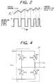
- Fig. 2 shows relations among the gate signal, output current waveform, and current instruction value in this instance.
- a gate control signal is transmitted so that the output current almost coincides with the current instruction value. Namely, when the gate signal is at the high (H) level, the output current increases. When the output current exceeds the instruction value by a predetermined amount or more, the gate signal is set to the low (L) level, thereby reducing the output current.
- the gate signal When the output current is lower than the instruction value by a predetermined amount or more, the gate signal is again set to the H level, thereby increasing the output current. By such a control operation, the output current is almost made coincide with the instruction value.
- the highest frequency of the gate signal is set to a fairly high value in a range from about 10 kHz to 30 kHz.
- the maximum power control unit and instant value current control unit are ordinarily individually constructed. This is because control speeds which are required for the maximum power control and the instant value current control are quite different. Since it is sufficient that the maximum power control unit merely traces a fluctuation of the insolation, a control unit of a relatively slow can be used. According to the study of the inventors et al., it is sufficient that the control unit can operate at a slow period such as 0.1 second. However, the instant value current control system continuously compares the output current with the current instruction value and must decide an on/off of the gate from the comparison result. Moreover, in order to reduce an output current distortion and noises, it is required to turn on/off the switching unit at a frequency of 10 kHz or higher.
- the instant value current control unit constructed like a hardware and the maximum power control unit constructed like a software are combined as mentioned above.
- the hardware since two control units of the hardware and the digital microprocessor are provided, the costs rise and an installing place is necessary. When a new switching device appears, it is necessary to change the design of the hardware of the current control unit.
- the invention is made in consideration of the above problems and it is an object of the invention to provide a cheap inverter which uses a single digital microprocessor and which can execute a current control and a maximum power control without changing a design of a hardware even for any switching device or solar cell.
- Another object of the invention is to provide a control apparatus of an inverter for converting a DC electric power into an AC electric power by using a switching device and for reversely supplying to a commercially available power source system, comprising: inversion discriminating means for comparing an output current or an output voltage of the inverter with a predetermined reference signal, thereby discriminating whether a switching state of the switching device is inverted or not; and gate pulse signal forming means for inverting the switching state of the switching device in response to an inversion request signal which is outputted from the discriminating means and, wherein the gate pulse signal forming means is constructed by a digital CPU, and the CPU receives the inversion request signal as an interruption control signal and forms a gate pulse signal to invert the switching state of the switching device in an inversion request interruption processing routine after the interruption control signal was inputted.
- Still another object of the invention is to provide a power generation system comprising: an inverter having such a control apparatus; a solar cell for supplying a DC electric power to the inverter; and a commercially available power source system as an additional device of the inverter, wherein an output electric power of the solar cell is reversely supplied to the commercially available power source system.
- a control apparatus of an inverter for converting a DC electric power into an AC electric power by using a switching device comprising: an inversion discrimination circuit for receiving an output current or an output voltage and a reference signal, thereby discriminating whether a switching state of the switching device should be inverted or not; and gate pulse signal forming means for changing the switching state of the switching device in response to an inversion request signal which is outputted from the inversion discrimination circuit and, wherein the gate pulse signal forming means is constructed by a CPU and inputs the inversion request signal as an interruption control signal of the CPU.
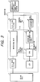
- Fig. 3 shows a preferred example of a construction of a solar power generation system using an inverter according to the invention.
- Reference numeral 4 denotes a CPU (central processing unit); 5 an inversion discrimination circuit; and 6 a converter.
- the converter 6 is connected to the commercially available power source system 3 and supplies a desired current value as a reference current to the inversion discrimination circuit 5.
- An output current from the switching unit 22 is supplied to the inversion discrimination circuit 5.
- an analog comparator and a proper main process by the CPU are combined and an all-off time to turn off all of the switches of the switching unit 22 is set.
- a gate driving circuit (not shown) of the switching unit 22 is directly driven by a digital output signal from the digital CPU 4.
- a switch inversion request signal from the inversion discrimination circuit 5 is coupled to an interruption signal line of the CPU 4.
- a solar cell 1 there is a cell such that amorphous silicon or crystal silicon is used in a photoelectric converting layer.
- amorphous silicon or crystal silicon is used in a photoelectric converting layer.
- 56 (14 series ⁇ 4 parallel) amorphous solar cell modules (trade name: UPM880) made by USSC Co., Ltd. are used as a solar cell 1 and an array having an output of 200V and 5.6A is constructed.
- the output of the solar cell 1 is inputted to the switching unit 22 through the DC side filter 21 having a capacitor of a large capacitance.
- an aluminum electrolytic capacitor of 4700 ⁇ F is used as a capacitor of the DC side filter 21. As such a capacitor, it is necessary to select a capacitor such that it can withstand a ripple current and a release voltage of the solar cell 1.
- a switching unit 22 what is called a full bridge circuit using four self arc-extinguishing type switching devices such as MOSFETs, IGBTs, or the like is preferably used.
- a half bridge circuit using two devices or the like can be also used.
- a full bridge circuit shown in Fig. 4 is constructed by using four MOSFETs (2SK1405: 600V and 15A) made by Hitachi Ltd..
- the output of the switching unit 22 is connected to the commercially available power source system (100V, 60 Hz) through an output reactor (10A, 10 mH).
- the four MOSFETs have two sets (221 and 222; 223 and 224) of MOSFETs in each of which a source S and a drain D are interconnected.
- the drains D of the MOSFETs (221 and 223), of which is source S is interconnected, are respectively connected to the positive (+) terminal.
- the sources S of the MOSFETs (222 and 224), of which are interconnected drains D, are respectively connected to the negative (-) terminal. Outputs are taken out from the nodes where the sources S and drains D of the MOSFETs are connected.
- An output from the CPU 4 is supplied to a gate G of each MOSFET.
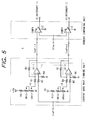
- a current trace control type is used as an instant value current control system (inversion discrimination system).
- Fig. 5 shows a specific example of a circuit to execute it.
- a voltage obtained by multiplying a predetermined constant to a system voltage is applied as a reference current to a reference signal input terminal Iref.
- An inverter output current is supplied to an output current input terminal Iinv and is compared by comparators COMP1 and COMP2, respectively. Inversion request signals having opposite phases are outputted.
- R1 to R9 and R12 denote fixed resistors and VR10, VR11, VR13, and VR14 indicate variable resistors, respectively.
- CMOS complementary metal-oxide-semiconductor
- TTL digital levels
- the outputs R and S of the inversion discrimination circuit 5 are connected to the interruption input terminal of the digital CPU. It is desirable to use a CPU having a plurality of interruption input terminals. Unless otherwise, it is sufficient to enable a plurality of interruption inputs to be connected by using a circuit for an interruption control as represented by an IC (model name, 8251) made by Intel Co., Ltd.
- a micomboard for learning (trade name; MTK7702A) made by Mitsubishi Electric Corporation is used.
- a device M7710 (made by Mitsubishi Electric Corporation; clock frequency is 25 MHz) is installed as a CPU on the board.
- Such a CPU is what is called a 1-chip type and has an A/D converter, a D/A converter, a timer, a parallel I/O, an RAM, and three interruption input terminals.
- the CPU is suitable for embodying the invention.
- the outputs R and S are connected to an interruption 0 and an interruption 1, respectively. Bits 0 to 4 of a parallel port No. 6 are used as a gate pulse.
- An output of the parallel port is insulated by a photocoupler and, after that, it is sent to a gate driving circuit of the switching device.
- a well-known circuit can be used as a gate driving circuit. In many cases, since recommended gate driving circuits are disclosed in brochures of the power devices of respective companies, they can be also used.
- a process for flickering an LED connected to the fifth parallel port of the CPU M7710 is executed in the main control process.
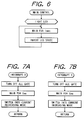
- Fig. 6 shows such a main control process.
- the operation which is described by the main control routine must have a delay control (response) time slower than a switch inverting operation. Unless otherwise, a time for an interrupting process becomes an amount that cannot be relatively ignored and obstructs the operation.
- the description contents of the interruption processing routine is as shown in Figs. 7A and 7B.
- the process for ALLOFF all of the switching devices are turned off.
- the ALLOFF process is executed for a time of 2 ⁇ seconds) is executed for a predetermined time. After that, a status inversion to a current increasing mode (the FETs 221 and 224 are turned on) and a current decreasing mode (the FETs 222 and 223 are turned on) is executed.
- the ALLOFF process it is possible to prevent an accident such that the switching devices (the FETs 221 and 222, the FETs 223 and 224 in Fig.
- an ALLOFF time is decided in a software manner.
- the control apparatus of the embodiment doesn't need the change of hardware which requires a time and costs. Since the switching operation can be intelligently executed by the CPU, many various processes can be performed for an unexpected situation and a safety as a system can be raised.
- the control apparatus while executing the flickering operation of the LED after resetting, only when there is a switch inversion interruption, the switch inversion is performed and the output current waveform is controlled.
- the control processing program since the phase synchronization with the system is automatically accomplished by the reference current Iref to the inversion discrimination circuit, the control processing program is remarkably simple as mentioned above.
- IGBT (CM50DY-12H) made by Mitsubishi Electric Corporation is used as a switching device and the other hardware construction is substantially the same as the embodiment 1.
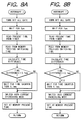
- the description of the interruption processing routine is changed as shown in Figs. 8A and 8B. Specifically speaking, a time from the previous inversion is measured by using a timer. When the measured time is too short, a time waiting process is executed.
- the shortest switch time is set to 0.1 msec. By performing a limiting process of the shortest switch time as mentioned above, a switching frequency can be limited to 10 kHz or less. Since the switching operation of the IGBT is slower than that of the MOSFET, it is necessary to limit the switching frequency. However, in the control apparatus of the invention, there is no need to modify the hardware in association with it.
- a memory for storing the time is commonly used for the interruption 0 and the interruption 1.
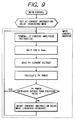
- the main control routine is rewritten as shown in Fig. 9 and the optimum operation point trace (MPPT) control operation is executed by the main control routine.
- MPPT optimum operation point trace
- a current amplitude instruction is renewed and the apparatus waits for 0.1 second. Subsequently, a PV (solar cell) current/voltage is read and a PV electric power is calculated. A check is now made to see if the PV (solar cell) electric power has increased than the previous calculation result. If YES, the current amplitude instruction is renewed. When the PV power is not increased than the previous calculation result, the current instructing mode is inverted. After that, the current amplitude instruction is renewed.
- the current instruction is renewed in accordance with an increase or decrease in PV power.
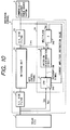
- a circuit is constructed as shown in Fig. 10 so that the micomboard can also fetch the solar cell voltage and current to the A/D input terminal.
- the voltage of the solar cell is dropped by a proper voltage dividing resistor and, after that, the dropped voltage is inputted to the A/D input terminal by using an insulating amplifier.
- the current is converted into the voltage by using a DCCT (DC current transformer) using a Hall element and the voltage is inputted to the A/D input terminal of the CPU.
- DCCT DC current transformer
- An output of a D/A converter is multiplied to the system voltage by an analog multiplier 243 and the resultant voltage is used as a reference current Iref, thereby enabling a magnitude of an inverter output current to be controlled by the CPU.
- the maximum power control unit 241 is assembled in the CPU 4.
- mountain climbing method As an MPPT control operation method.
- the mountain climbing method is used.
- a portion surrounded by a broken line in Fig. 9 mentioned above shows a flowchart for the mountain climbing method. Namely, the current instruction value is increased, a PV power at that time is calculated, and when the power drops, the current instruction value is decreased and, when the power rises, the current instruction value is further increased.
- a waiting time of 100 msec (0.1 second) is provided for a control loop in order to allow the inverter to trace the operation. Even if there is a waiting time for limiting the switching time, a processing time of the interruption processing routine is at most 0.2 msec or less. Therefore, there is a difference of 500 times between both of the above control times.
- the inverter of the embodiment When the apparatus is operated in a day under a blue sky as mentioned above, the inverter of the embodiment doesn't abnormally operate but execute the maximum power point tracing operation. No problem occurred with respect to an output current distortion and the shortest switching time.
- the MPPT operation and the output waveform forming operation can be embodied by the single CPU.
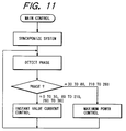
- FIG. 11 shows a flowchart of an example of a program for processing the waveform formation and the main control operation by only a software.
- relatively complicated processes such as system synchronizing process, phase discriminating process, and the like are necessary.
- the control apparatus of the system linkage inverter for converting the DC electric power into the AC electric power by using the switching device and reversely supplying the AC electric power to the commercially available power source system, comprising: the inversion discriminating means for inputting an output current or output voltage and a reference signal and for discriminating whether a switching state of the switching device is inverted or not; and the gate pulse signal forming means for changing the switching state of the switching device in response to an inversion request signal which is outputted from the inversion discriminating means and, wherein the gate pulse signal forming means is constructed by the digital CPU and the inversion request signal is inputted as an interruption control signal of the CPU.
- the control apparatus has the following effects.
- a control apparatus of an inverter for converting a DC electric power into an AC electric power by using a switching device, wherein the control apparatus is constructed by an inversion discrimination circuit 5 for receiving an output current or an output voltage and a reference signal and for discriminating whether a switching state of the switching device should be inverted or not and a gate pulse signal forming unit for changing the switching state of the switching device in response to an inversion request signal which is outputted from the inversion discrimination circuit.
- the gate pulse signal forming unit has a CPU 4 for forming a gate pulse signal by an interrupting process by using the inversion request signal as an interruption control signal.
Landscapes
- Engineering & Computer Science (AREA)
- Power Engineering (AREA)
- Inverter Devices (AREA)
- Control Of Electrical Variables (AREA)
- Direct Current Feeding And Distribution (AREA)
- Charge And Discharge Circuits For Batteries Or The Like (AREA)
Abstract
Description
- The invention relates to a control apparatus of an inverter and a power generation system using such a control apparatus. More particularly, the invention relates to a control apparatus of a system linkage inverter which is linked to a commercially available power source system and a power generation system using such a control apparatus and capable of coping with an unstable power generation such as a solar power generation.
- A solar power generation system converts an inexhaustible clean solar energy into an electric power and is largely expected. Particularly, in recent years, a legal preparation is progressing and a system linkage system for converting a DC electric power which is generated by a solar cell into an AC power by using an inverter and for supplying the AC power to the commercially available power source system can be used on a full scale. Fig. 1 shows an example of a general solar power generation system. An output of a
solar cell 1 is connected to a commercially available power source system 3 through a system linkage inverter (hereinafter, simply referred to as an inverter) 2. Theinverter 2 has therein: an input filter (DC side filter) 21 having a coil and a capacitor; aswitching unit 22 having a semiconductor switch which is on/off controlled by a gate control signal and the like; an output filter (AC side filter) 23 having a coil and a capacitor; and acontrol apparatus 24 for controlling the operation of an inverter. Thecontrol apparatus 24 has a maximumpower control unit 241 and an instant valuecurrent control unit 242. Theinverter 2 can also have a protecting apparatus and the like. - The maximum
power control unit 241 changes an operation point of a solar cell in accordance with a change in insolation intensity or temperature, thereby extracting the maximum electric power from the solar cell. Thecontrol unit 241 inputs a solar cell voltage Vpv and a solar cell current Ipv and arithmetically operates an output current instruction value of the inverter so that a solar cell output becomes maximum. More particularly, thecontrol unit 241 arithmetically operates and calculates a voltage such that the solar cell electric power becomes maximum and controls the current instruction value so that the solar cell voltage is equal to such a voltage. It is a general way to use a digital microprocessor (what is called a micom) as an arithmetic operating apparatus. As an example of such a maximum power control unit, there is a unit as disclosed in Japanese Patent Application Laid-open No. 62-85312. - The instant value
current control unit 242 inputs the current instruction value from the maximumpower control unit 241 and controls theswitching unit 22 by a gate control signal so that an output current of the inverter almost coincides with the current instruction value. As an example of such an instant value current control unit, there is a unit as disclosed in U.S. Patent No. 4,424,557. - An example of the operation of the instant value current control unit will now be described with reference to Figs. 1 and 2. The instant value
current control unit 242 inputs the current instruction value from the maximumpower control unit 241 and sends a gate control signal (on/off) instruction signal to theswitching unit 22. Fig. 2 shows relations among the gate signal, output current waveform, and current instruction value in this instance. As shown in Fig. 2, as for the instant value current control signal, a gate control signal is transmitted so that the output current almost coincides with the current instruction value. Namely, when the gate signal is at the high (H) level, the output current increases. When the output current exceeds the instruction value by a predetermined amount or more, the gate signal is set to the low (L) level, thereby reducing the output current. When the output current is lower than the instruction value by a predetermined amount or more, the gate signal is again set to the H level, thereby increasing the output current. By such a control operation, the output current is almost made coincide with the instruction value. In the inverter for solar power generation system, in order to reduce noises and an output current distortion, in many cases, the highest frequency of the gate signal is set to a fairly high value in a range from about 10 kHz to 30 kHz. - The maximum power control unit and instant value current control unit are ordinarily individually constructed. This is because control speeds which are required for the maximum power control and the instant value current control are quite different. Since it is sufficient that the maximum power control unit merely traces a fluctuation of the insolation, a control unit of a relatively slow can be used. According to the study of the inventors et al., it is sufficient that the control unit can operate at a slow period such as 0.1 second. However, the instant value current control system continuously compares the output current with the current instruction value and must decide an on/off of the gate from the comparison result. Moreover, in order to reduce an output current distortion and noises, it is required to turn on/off the switching unit at a frequency of 10 kHz or higher. For example, in order to realize a switching speed of 10 kHz, it is necessary to suppress a control period to a value less than at most 100 microseconds. If both of the control operations are executed by one digital microprocessor, all of control logics can be assembled as a software, so that a flexibility of the system remarkably rises. However, if such a construction is ordinarily embodied, both of the maximum power control and the instant value current control are executed in the control period (for example, 100 µsec), so that an extremely high speed microprocessor and an extremely high speed analog/digital converter are necessary. They are very expensive and there is a problem such that the inverter cannot be cheaply constructed. Therefore, in general, the instant value current control unit constructed like a hardware and the maximum power control unit constructed like a software are combined as mentioned above. Although it is easy to perform the instant value current control by the hardware, since two control units of the hardware and the digital microprocessor are provided, the costs rise and an installing place is necessary. When a new switching device appears, it is necessary to change the design of the hardware of the current control unit.
- An inverter control apparatus using an interruption by a timer has been disclosed in Japanese Patent Application Laid-open No. 57-25171. However, such an apparatus cannot be applied to an inverter having an input such that it successively changes in accordance with an insolation like a solar cell.
- As mentioned above, a proper control apparatus suitable for a linkage inverter to perform the instant value current control (waveform formation control) and the maximum power control by using a single CPU is not yet realized.
- The invention is made in consideration of the above problems and it is an object of the invention to provide a cheap inverter which uses a single digital microprocessor and which can execute a current control and a maximum power control without changing a design of a hardware even for any switching device or solar cell.
- Another object of the invention is to provide a control apparatus of an inverter for converting a DC electric power into an AC electric power by using a switching device and for reversely supplying to a commercially available power source system, comprising: inversion discriminating means for comparing an output current or an output voltage of the inverter with a predetermined reference signal, thereby discriminating whether a switching state of the switching device is inverted or not; and gate pulse signal forming means for inverting the switching state of the switching device in response to an inversion request signal which is outputted from the discriminating means and, wherein the gate pulse signal forming means is constructed by a digital CPU, and the CPU receives the inversion request signal as an interruption control signal and forms a gate pulse signal to invert the switching state of the switching device in an inversion request interruption processing routine after the interruption control signal was inputted.
- Still another object of the invention is to provide a power generation system comprising: an inverter having such a control apparatus; a solar cell for supplying a DC electric power to the inverter; and a commercially available power source system as an additional device of the inverter, wherein an output electric power of the solar cell is reversely supplied to the commercially available power source system.
- To accomplish the above object, according to the invention, there is provided a control apparatus of an inverter for converting a DC electric power into an AC electric power by using a switching device, comprising: an inversion discrimination circuit for receiving an output current or an output voltage and a reference signal, thereby discriminating whether a switching state of the switching device should be inverted or not; and gate pulse signal forming means for changing the switching state of the switching device in response to an inversion request signal which is outputted from the inversion discrimination circuit and, wherein the gate pulse signal forming means is constructed by a CPU and inputs the inversion request signal as an interruption control signal of the CPU.
- When considering the switching operation of the inverter, it will be understood that a period of time when some process is functionally necessary is nothing but a moment for switching the switch. In the invention, by paying attention to such a point, the moment for inverting is discriminated by a hardware manner and an interruption request signal is generated, thereby allowing the CPU to execute the switching operation of the switch only for such an instantaneous time. With this method, the CPU ordinarily can devote itself to a process such as protecting process, maximum power process, or the like such that it has a relatively enough response time and can execute a process to form a switching gate pulse by using an interrupting process in an extremely short response time. With this method, since the gate pulse forming process is described as a software of the CPU, even when the switching device is changed, there is no need to change the hardware. Further, an independence of mutual processing routines is remarkably raised and a debugging can be easily performed.
-
- Fig. 1 is a schematic block constructional diagram for explaining a construction of a solar power generation system;
- Fig. 2 is a schematic explanatory diagram for explaining the relation between an output current value and a current instruction value;
- Figs. 3 and 10 are schematic block constructional diagrams each for explaining one of an example of a construction of a solar power generation system of the invention;
- Fig. 4 is a schematic circuit diagram for explaining an example of a switching unit;
- Fig. 5 is a schematic circuit constructional diagram for explaining an example of an inversion discrimination circuit;
- Figs. 6 and 9 are flowcharts each for explaining an example of a main control process;
- Figs. 7A, 7B, 8A and 8B are flowcharts each for explaining an example of an interrupting process; and
- Fig. 11 is a flowchart for explaining a main control process in a comparison example.
- Fig. 3 shows a preferred example of a construction of a solar power generation system using an inverter according to the invention.
- In Fig. 3, the same component elements as shown in Fig. 1 are designated by the same reference numerals.
Reference numeral 4 denotes a CPU (central processing unit); 5 an inversion discrimination circuit; and 6 a converter. The converter 6 is connected to the commercially available power source system 3 and supplies a desired current value as a reference current to theinversion discrimination circuit 5. An output current from the switchingunit 22 is supplied to theinversion discrimination circuit 5. - According to the
inverter 2 in Fig. 3, an analog comparator and a proper main process by the CPU are combined and an all-off time to turn off all of the switches of the switchingunit 22 is set. In Fig. 3, a gate driving circuit (not shown) of the switchingunit 22 is directly driven by a digital output signal from thedigital CPU 4. A switch inversion request signal from theinversion discrimination circuit 5 is coupled to an interruption signal line of theCPU 4. - As a
solar cell 1, there is a cell such that amorphous silicon or crystal silicon is used in a photoelectric converting layer. However, there is no limitation when embodying the invention. In the embodiment, 56 (14 series × 4 parallel) amorphous solar cell modules (trade name: UPM880) made by USSC Co., Ltd. are used as asolar cell 1 and an array having an output of 200V and 5.6A is constructed. - The output of the
solar cell 1 is inputted to theswitching unit 22 through theDC side filter 21 having a capacitor of a large capacitance. In the embodiment, an aluminum electrolytic capacitor of 4700 µF is used as a capacitor of theDC side filter 21. As such a capacitor, it is necessary to select a capacitor such that it can withstand a ripple current and a release voltage of thesolar cell 1. - As a
switching unit 22, what is called a full bridge circuit using four self arc-extinguishing type switching devices such as MOSFETs, IGBTs, or the like is preferably used. As another circuit, a half bridge circuit using two devices or the like can be also used. In the embodiment, a full bridge circuit shown in Fig. 4 is constructed by using four MOSFETs (2SK1405: 600V and 15A) made by Hitachi Ltd.. The output of the switchingunit 22 is connected to the commercially available power source system (100V, 60 Hz) through an output reactor (10A, 10 mH). - As shown in Fig. 4, the four MOSFETs have two sets (221 and 222; 223 and 224) of MOSFETs in each of which a source S and a drain D are interconnected. The drains D of the MOSFETs (221 and 223), of which is source S is interconnected, are respectively connected to the positive (+) terminal. The sources S of the MOSFETs (222 and 224), of which are interconnected drains D, are respectively connected to the negative (-) terminal. Outputs are taken out from the nodes where the sources S and drains D of the MOSFETs are connected. An output from the
CPU 4 is supplied to a gate G of each MOSFET. - A current trace control type is used as an instant value current control system (inversion discrimination system). Fig. 5 shows a specific example of a circuit to execute it. In the
inversion discrimination circuit 5 in Fig. 5, a voltage obtained by multiplying a predetermined constant to a system voltage is applied as a reference current to a reference signal input terminal Iref. An inverter output current is supplied to an output current input terminal Iinv and is compared by comparators COMP1 and COMP2, respectively. Inversion request signals having opposite phases are outputted. - R1 to R9 and R12 denote fixed resistors and VR10, VR11, VR13, and VR14 indicate variable resistors, respectively.
- Resistance values of those resistors are set as follows: R1 to R8 = 100 kΩ; R9, R12 = 5.1 kΩ; VR10, VR13 = 500 Ω; and VR11, VR14 = 200 Ω.
- A state of the operation of the
inversion discrimination circuit 5 will now be explained with reference to Fig. 2. When a difference between the reference current Iref and the output current Iinv is out of a predetermined current width Δ, an output occurs so that an inversion request signal R or S is set to the high logic level H. In the embodiment, general operational amplifiers TL072 are used as arithmetic operational amplifiers U1-1 and U1-2 and MAX909 made by Maxim Co., Ltd. in which an output is at the TTL level and an operating speed is high is used as a comparator. Particularly, although there is no severe limitation with respect to those devices, in order to connect to the digital CPU, it is convenient to use devices such that digital levels (CMOS, TTL) are outputted to the outputs R and S. It is necessary to set the current width Δ to a proper value in consideration of an efficiency and a distortion of the inverter. Generally, when Δ is reduced, the number of switching times increases and an efficiency deteriorates. However, a distortion decreases. When Δ is increased, the opposite phenomena occur. Therefore, it is necessary to decide the current width Δ in consideration of conditions such as a distortion and the like. - The outputs R and S of the
inversion discrimination circuit 5 are connected to the interruption input terminal of the digital CPU. It is desirable to use a CPU having a plurality of interruption input terminals. Unless otherwise, it is sufficient to enable a plurality of interruption inputs to be connected by using a circuit for an interruption control as represented by an IC (model name, 8251) made by Intel Co., Ltd. - In the embodiment, a micomboard for learning (trade name; MTK7702A) made by Mitsubishi Electric Corporation is used. A device M7710 (made by Mitsubishi Electric Corporation; clock frequency is 25 MHz) is installed as a CPU on the board. Such a CPU is what is called a 1-chip type and has an A/D converter, a D/A converter, a timer, a parallel I/O, an RAM, and three interruption input terminals. The CPU is suitable for embodying the invention. In the embodiment, the outputs R and S are connected to an
interruption 0 and aninterruption 1, respectively.Bits 0 to 4 of a parallel port No. 6 are used as a gate pulse. - An output of the parallel port is insulated by a photocoupler and, after that, it is sent to a gate driving circuit of the switching device. A well-known circuit can be used as a gate driving circuit. In many cases, since recommended gate driving circuits are disclosed in brochures of the power devices of respective companies, they can be also used.
- An inverter control apparatus according to the invention is constructed as mentioned above. A construction of a software will now be described.
- In the control apparatus of the invention, it is necessary to describe two independent processing programs of a switch inversion processing routine described as an interrupting process and a main control routine for executing other processes such as an optimum operation point trace control and the like. In case of the invention, since the mutual programs don't need to be aware of their existence, the program can be fairly easily described and a maintenance performance is raised.
- According to the embodiment, a process for flickering an LED connected to the fifth parallel port of the CPU M7710 is executed in the main control process. Fig. 6 shows such a main control process. The operation which is described by the main control routine must have a delay control (response) time slower than a switch inverting operation. Unless otherwise, a time for an interrupting process becomes an amount that cannot be relatively ignored and obstructs the operation.
- The description contents of the interruption processing routine is as shown in Figs. 7A and 7B. The process for ALLOFF (all of the switching devices are turned off. In the embodiment, the ALLOFF process is executed for a time of 2 µseconds) is executed for a predetermined time. After that, a status inversion to a current increasing mode (the
FETs FETs FETs FETs - According to the control apparatus, while executing the flickering operation of the LED after resetting, only when there is a switch inversion interruption, the switch inversion is performed and the output current waveform is controlled. In the apparatus, since the phase synchronization with the system is automatically accomplished by the reference current Iref to the inversion discrimination circuit, the control processing program is remarkably simple as mentioned above.
- In the embodiment, IGBT (CM50DY-12H) made by Mitsubishi Electric Corporation is used as a switching device and the other hardware construction is substantially the same as the
embodiment 1. The description of the interruption processing routine is changed as shown in Figs. 8A and 8B. Specifically speaking, a time from the previous inversion is measured by using a timer. When the measured time is too short, a time waiting process is executed. In the embodiment, the shortest switch time is set to 0.1 msec. By performing a limiting process of the shortest switch time as mentioned above, a switching frequency can be limited to 10 kHz or less. Since the switching operation of the IGBT is slower than that of the MOSFET, it is necessary to limit the switching frequency. However, in the control apparatus of the invention, there is no need to modify the hardware in association with it. A memory for storing the time is commonly used for theinterruption 0 and theinterruption 1. - In the embodiment, in addition to the foregoing embodiments, the main control routine is rewritten as shown in Fig. 9 and the optimum operation point trace (MPPT) control operation is executed by the main control routine.
- Namely, after the current instruction value increasing mode was set, a current amplitude instruction is renewed and the apparatus waits for 0.1 second. Subsequently, a PV (solar cell) current/voltage is read and a PV electric power is calculated. A check is now made to see if the PV (solar cell) electric power has increased than the previous calculation result. If YES, the current amplitude instruction is renewed. When the PV power is not increased than the previous calculation result, the current instructing mode is inverted. After that, the current amplitude instruction is renewed.
- As mentioned above, the current instruction is renewed in accordance with an increase or decrease in PV power. In association with the optimum operation point trace, a circuit is constructed as shown in Fig. 10 so that the micomboard can also fetch the solar cell voltage and current to the A/D input terminal.
- To fetch the solar cell voltage, it is a general way that the voltage of the solar cell is dropped by a proper voltage dividing resistor and, after that, the dropped voltage is inputted to the A/D input terminal by using an insulating amplifier. To fetch the solar cell current, after insulating, it is sufficient that the current is converted into the voltage by using a DCCT (DC current transformer) using a Hall element and the voltage is inputted to the A/D input terminal of the CPU. As other methods, there are a method of using a precise resistor for a current detection and the like. An output of a D/A converter is multiplied to the system voltage by an
analog multiplier 243 and the resultant voltage is used as a reference current Iref, thereby enabling a magnitude of an inverter output current to be controlled by the CPU. The maximumpower control unit 241 is assembled in theCPU 4. - There is a mountain climbing method as an MPPT control operation method. In the embodiment, the mountain climbing method is used. A portion surrounded by a broken line in Fig. 9 mentioned above shows a flowchart for the mountain climbing method. Namely, the current instruction value is increased, a PV power at that time is calculated, and when the power drops, the current instruction value is decreased and, when the power rises, the current instruction value is further increased. A waiting time of 100 msec (0.1 second) is provided for a control loop in order to allow the inverter to trace the operation. Even if there is a waiting time for limiting the switching time, a processing time of the interruption processing routine is at most 0.2 msec or less. Therefore, there is a difference of 500 times between both of the above control times.
- When the apparatus is operated in a day under a blue sky as mentioned above, the inverter of the embodiment doesn't abnormally operate but execute the maximum power point tracing operation. No problem occurred with respect to an output current distortion and the shortest switching time. As mentioned above, the MPPT operation and the output waveform forming operation can be embodied by the single CPU.
- As a comparison example, Fig. 11 shows a flowchart of an example of a program for processing the waveform formation and the main control operation by only a software. In this case, relatively complicated processes such as system synchronizing process, phase discriminating process, and the like are necessary.
- As mentioned above, according to the invention, there is provided the control apparatus of the system linkage inverter for converting the DC electric power into the AC electric power by using the switching device and reversely supplying the AC electric power to the commercially available power source system, comprising: the inversion discriminating means for inputting an output current or output voltage and a reference signal and for discriminating whether a switching state of the switching device is inverted or not; and the gate pulse signal forming means for changing the switching state of the switching device in response to an inversion request signal which is outputted from the inversion discriminating means and, wherein the gate pulse signal forming means is constructed by the digital CPU and the inversion request signal is inputted as an interruption control signal of the CPU. The control apparatus has the following effects.
- (1) The parameters such as ALLOFF time and shortest switching time which are peculiar to the switching device can be easily changed.
- (2) The gate block function can be easily realized.
- (3) The lowest or highest switching frequency can be easily limited.
- (4) In the solar power generation, the MPPT control unit and the waveform control unit can be constructed by a cheap single CPU of a relatively slow speed. Thus, the costs of the inverter control apparatus can be reduced.
- (5) Since the interrupting process is used, the maximum power control process and the waveform formation control (gate pulse generating) process can be described as exactly independent programs. Therefore, the debugging of each process can be also independently easily executed and a developing efficiency can be raised.
- To provide a cheap inverter which uses a single digital microprocessor and can execute a current control and a maximum power control without changing a design of a hardware even for any switching device or solar cell, there is provided a control apparatus of an inverter for converting a DC electric power into an AC electric power by using a switching device, wherein the control apparatus is constructed by an
inversion discrimination circuit 5 for receiving an output current or an output voltage and a reference signal and for discriminating whether a switching state of the switching device should be inverted or not and a gate pulse signal forming unit for changing the switching state of the switching device in response to an inversion request signal which is outputted from the inversion discrimination circuit. The gate pulse signal forming unit has aCPU 4 for forming a gate pulse signal by an interrupting process by using the inversion request signal as an interruption control signal.
Claims (5)
- A control apparatus of an inverter for converting a DC electric power into an AC electric power by using a switching device and for reversely supplying said AC electric power to a commercially available power source system, comprising:inversion discriminating means for comparing an output current or an output voltage of said inverter with a predetermined reference signal, thereby discriminating whether a switching state of said switching device is inverted or not; andgate pulse signal forming means for inverting the switching state of said switching device in response to an inversion request signal which is outputted from said discriminating means,wherein said gate pulse signal forming means has a digital CPU and said CPU receives said inversion request signal as an interruption control signal and forms a gate pulse signal to invert the switching state of said switching device in an inversion request interruption processing routine after said interruption control signal was inputted.
- An apparatus according to Claim 1, wherein said gate pulse signal forming means inverts the switching state of said switching device to a first state in which the output voltage of said inverter is applied to said commercially available power source system by a first polarity or a second state in which said output voltage is applied by a polarity opposite to said first polarity.
- An apparatus according to claim 2, further having time measuring means, and wherein said digital CPU obtains a time difference between a previous inversion request and a present inversion request in said inversion request interruption processing routine on the basis of an output of said time measuring means, and when said time difference is shorter than a predetermined time, the CPU waits for the inversion of the switching state of said switching device until a time reaches said predetermined time.
- A solar power generation system comprising:an inverter having a control apparatus according to claim 1;a solar cell for supplying a DC electric power to said inverter; anda commercially available power source system as an additional system of said inverter,wherein the output electric power of said solar cell is reversely supplied to said commercially available power source system.
- A system according to claim 4, wherein in addition to the process to change said switching state, a digital CPU of said control apparatus also simultaneously executes a maximum power control process for controlling an operating voltage of the solar cell so as to be take out a maximum power from the solar cell.
Applications Claiming Priority (3)
| Application Number | Priority Date | Filing Date | Title |
|---|---|---|---|
| JP20935795A JP3651972B2 (en) | 1995-07-26 | 1995-07-26 | Control device for grid-connected inverter and photovoltaic power generation system using the same |
| JP20935795 | 1995-07-26 | ||
| JP209357/95 | 1995-07-26 |
Publications (2)
| Publication Number | Publication Date |
|---|---|
| EP0756372A1 true EP0756372A1 (en) | 1997-01-29 |
| EP0756372B1 EP0756372B1 (en) | 2002-12-11 |
Family
ID=16571612
Family Applications (1)
| Application Number | Title | Priority Date | Filing Date |
|---|---|---|---|
| EP96112032A Expired - Lifetime EP0756372B1 (en) | 1995-07-26 | 1996-07-25 | Control apparatus of inverter and power generation system using such control apparatus |
Country Status (6)
| Country | Link |
|---|---|
| US (1) | US6031736A (en) |
| EP (1) | EP0756372B1 (en) |
| JP (1) | JP3651972B2 (en) |
| KR (1) | KR100263826B1 (en) |
| CN (1) | CN1049080C (en) |
| DE (1) | DE69625290T2 (en) |
Cited By (57)
| Publication number | Priority date | Publication date | Assignee | Title |
|---|---|---|---|---|
| WO2002073785A1 (en) * | 2001-03-14 | 2002-09-19 | International Power Systems, Inc. | Converter/inverter controller |
| US6738692B2 (en) | 2001-06-25 | 2004-05-18 | Sustainable Energy Technologies | Modular, integrated power conversion and energy management system |
| RU2377632C2 (en) * | 2008-01-29 | 2009-12-27 | Государственное образовательное учреждение высшего профессионального образования Иркутский государственный университет путей сообщения (ИрГУПС) | Method of power control and monophase converter device |
| US7808125B1 (en) | 2006-07-31 | 2010-10-05 | Sustainable Energy Technologies | Scheme for operation of step wave power converter |
| US8031495B2 (en) | 2007-06-04 | 2011-10-04 | Sustainable Energy Technologies | Prediction scheme for step wave power converter and inductive inverter topology |
| EP2328262A3 (en) * | 2009-11-27 | 2012-06-20 | General Electric Company | Apparatus And Method For DC/AC Systems To Ride Through Grid Transients |
| US9112379B2 (en) | 2006-12-06 | 2015-08-18 | Solaredge Technologies Ltd. | Pairing of components in a direct current distributed power generation system |
| US9130401B2 (en) | 2006-12-06 | 2015-09-08 | Solaredge Technologies Ltd. | Distributed power harvesting systems using DC power sources |
| US9235228B2 (en) | 2012-03-05 | 2016-01-12 | Solaredge Technologies Ltd. | Direct current link circuit |
| US9291696B2 (en) | 2007-12-05 | 2016-03-22 | Solaredge Technologies Ltd. | Photovoltaic system power tracking method |
| US9318974B2 (en) | 2014-03-26 | 2016-04-19 | Solaredge Technologies Ltd. | Multi-level inverter with flying capacitor topology |
| US9362743B2 (en) | 2008-05-05 | 2016-06-07 | Solaredge Technologies Ltd. | Direct current power combiner |
| US9368964B2 (en) | 2006-12-06 | 2016-06-14 | Solaredge Technologies Ltd. | Distributed power system using direct current power sources |
| US9401599B2 (en) | 2010-12-09 | 2016-07-26 | Solaredge Technologies Ltd. | Disconnection of a string carrying direct current power |
| US9407161B2 (en) | 2007-12-05 | 2016-08-02 | Solaredge Technologies Ltd. | Parallel connected inverters |
| CN105846534A (en) * | 2016-03-22 | 2016-08-10 | 中国大唐集团科学技术研究院有限公司 | Solar power generation system |
| US9537445B2 (en) | 2008-12-04 | 2017-01-03 | Solaredge Technologies Ltd. | Testing of a photovoltaic panel |
| US9543889B2 (en) | 2006-12-06 | 2017-01-10 | Solaredge Technologies Ltd. | Distributed power harvesting systems using DC power sources |
| US9548619B2 (en) | 2013-03-14 | 2017-01-17 | Solaredge Technologies Ltd. | Method and apparatus for storing and depleting energy |
| US9590526B2 (en) | 2006-12-06 | 2017-03-07 | Solaredge Technologies Ltd. | Safety mechanisms, wake up and shutdown methods in distributed power installations |
| US9644993B2 (en) | 2006-12-06 | 2017-05-09 | Solaredge Technologies Ltd. | Monitoring of distributed power harvesting systems using DC power sources |
| US9647442B2 (en) | 2010-11-09 | 2017-05-09 | Solaredge Technologies Ltd. | Arc detection and prevention in a power generation system |
| US9673711B2 (en) | 2007-08-06 | 2017-06-06 | Solaredge Technologies Ltd. | Digital average input current control in power converter |
| US9680304B2 (en) | 2006-12-06 | 2017-06-13 | Solaredge Technologies Ltd. | Method for distributed power harvesting using DC power sources |
| US9812984B2 (en) | 2012-01-30 | 2017-11-07 | Solaredge Technologies Ltd. | Maximizing power in a photovoltaic distributed power system |
| US9819178B2 (en) | 2013-03-15 | 2017-11-14 | Solaredge Technologies Ltd. | Bypass mechanism |
| US9831824B2 (en) | 2007-12-05 | 2017-11-28 | SolareEdge Technologies Ltd. | Current sensing on a MOSFET |
| US9853538B2 (en) | 2007-12-04 | 2017-12-26 | Solaredge Technologies Ltd. | Distributed power harvesting systems using DC power sources |
| US9853565B2 (en) | 2012-01-30 | 2017-12-26 | Solaredge Technologies Ltd. | Maximized power in a photovoltaic distributed power system |
| US9866098B2 (en) | 2011-01-12 | 2018-01-09 | Solaredge Technologies Ltd. | Serially connected inverters |
| US9869701B2 (en) | 2009-05-26 | 2018-01-16 | Solaredge Technologies Ltd. | Theft detection and prevention in a power generation system |
| US9876430B2 (en) | 2008-03-24 | 2018-01-23 | Solaredge Technologies Ltd. | Zero voltage switching |
| US9923516B2 (en) | 2012-01-30 | 2018-03-20 | Solaredge Technologies Ltd. | Photovoltaic panel circuitry |
| US9941813B2 (en) | 2013-03-14 | 2018-04-10 | Solaredge Technologies Ltd. | High frequency multi-level inverter |
| US9960667B2 (en) | 2006-12-06 | 2018-05-01 | Solaredge Technologies Ltd. | System and method for protection during inverter shutdown in distributed power installations |
| US9966766B2 (en) | 2006-12-06 | 2018-05-08 | Solaredge Technologies Ltd. | Battery power delivery module |
| US10115841B2 (en) | 2012-06-04 | 2018-10-30 | Solaredge Technologies Ltd. | Integrated photovoltaic panel circuitry |
| US10230310B2 (en) | 2016-04-05 | 2019-03-12 | Solaredge Technologies Ltd | Safety switch for photovoltaic systems |
| US10396662B2 (en) | 2011-09-12 | 2019-08-27 | Solaredge Technologies Ltd | Direct current link circuit |
| US10673222B2 (en) | 2010-11-09 | 2020-06-02 | Solaredge Technologies Ltd. | Arc detection and prevention in a power generation system |
| US10673229B2 (en) | 2010-11-09 | 2020-06-02 | Solaredge Technologies Ltd. | Arc detection and prevention in a power generation system |
| US10931119B2 (en) | 2012-01-11 | 2021-02-23 | Solaredge Technologies Ltd. | Photovoltaic module |
| US11018623B2 (en) | 2016-04-05 | 2021-05-25 | Solaredge Technologies Ltd. | Safety switch for photovoltaic systems |
| US11177663B2 (en) | 2016-04-05 | 2021-11-16 | Solaredge Technologies Ltd. | Chain of power devices |
| US11264947B2 (en) | 2007-12-05 | 2022-03-01 | Solaredge Technologies Ltd. | Testing of a photovoltaic panel |
| US11296650B2 (en) | 2006-12-06 | 2022-04-05 | Solaredge Technologies Ltd. | System and method for protection during inverter shutdown in distributed power installations |
| US11309832B2 (en) | 2006-12-06 | 2022-04-19 | Solaredge Technologies Ltd. | Distributed power harvesting systems using DC power sources |
| US11569660B2 (en) | 2006-12-06 | 2023-01-31 | Solaredge Technologies Ltd. | Distributed power harvesting systems using DC power sources |
| US11569659B2 (en) | 2006-12-06 | 2023-01-31 | Solaredge Technologies Ltd. | Distributed power harvesting systems using DC power sources |
| US11687112B2 (en) | 2006-12-06 | 2023-06-27 | Solaredge Technologies Ltd. | Distributed power harvesting systems using DC power sources |
| US11728768B2 (en) | 2006-12-06 | 2023-08-15 | Solaredge Technologies Ltd. | Pairing of components in a direct current distributed power generation system |
| US11735910B2 (en) | 2006-12-06 | 2023-08-22 | Solaredge Technologies Ltd. | Distributed power system using direct current power sources |
| US11855231B2 (en) | 2006-12-06 | 2023-12-26 | Solaredge Technologies Ltd. | Distributed power harvesting systems using DC power sources |
| US11881814B2 (en) | 2005-12-05 | 2024-01-23 | Solaredge Technologies Ltd. | Testing of a photovoltaic panel |
| US11888387B2 (en) | 2006-12-06 | 2024-01-30 | Solaredge Technologies Ltd. | Safety mechanisms, wake up and shutdown methods in distributed power installations |
| US12057807B2 (en) | 2016-04-05 | 2024-08-06 | Solaredge Technologies Ltd. | Chain of power devices |
| US12418177B2 (en) | 2009-10-24 | 2025-09-16 | Solaredge Technologies Ltd. | Distributed power system using direct current power sources |
Families Citing this family (44)
| Publication number | Priority date | Publication date | Assignee | Title |
|---|---|---|---|---|
| JP3697121B2 (en) * | 1998-10-15 | 2005-09-21 | キヤノン株式会社 | Photovoltaic power generation apparatus and control method thereof |
| FR2803139B1 (en) * | 1999-12-23 | 2007-12-21 | Delachaux Sa | ELECTRICAL SIGNAL GENERATOR WITH VARIABLE FREQUENCY, SERVICING AND LOW COST CALCULATION MEANS |
| JP3394996B2 (en) * | 2001-03-09 | 2003-04-07 | 独立行政法人産業技術総合研究所 | Maximum power operating point tracking method and device |
| RU2210101C2 (en) * | 2001-05-07 | 2003-08-10 | ОАО "Рязанский завод металлокерамических приборов" | Extreme power regulator |
| US6657419B2 (en) * | 2001-11-19 | 2003-12-02 | Solarmate Corporation | Micro-solar insolation circuit |
| US6858996B2 (en) * | 2002-08-14 | 2005-02-22 | International Rectifier Corporation | Driver IC for use with simple microcontrol |
| JP2004336943A (en) * | 2003-05-09 | 2004-11-25 | Canon Inc | Power converter |
| KR100708256B1 (en) * | 2004-11-16 | 2007-04-16 | 한양전공주식회사 | Power regulator with improved AC converter |
| JP4926482B2 (en) * | 2006-01-27 | 2012-05-09 | 東芝キヤリア株式会社 | Power converter |
| US9436198B2 (en) | 2006-03-23 | 2016-09-06 | Enphase Energy, Inc. | Method and apparatus for power conversion |
| US9461552B2 (en) | 2006-03-23 | 2016-10-04 | Enphase Energy, Inc. | Method and apparatus for power conversion |
| KR101212593B1 (en) * | 2006-03-23 | 2012-12-14 | 엔페이즈 에너지, 인코포레이티드 | Method and apparatus for converting direct current to alternating current |
| US9431828B2 (en) | 2006-11-27 | 2016-08-30 | Xslent Energy Technologies | Multi-source, multi-load systems with a power extractor |
| US7960870B2 (en) * | 2006-11-27 | 2011-06-14 | Xslent Energy Technologies, Llc | Power extractor for impedance matching |
| US8013474B2 (en) * | 2006-11-27 | 2011-09-06 | Xslent Energy Technologies, Llc | System and apparatuses with multiple power extractors coupled to different power sources |
| US9130390B2 (en) * | 2006-11-27 | 2015-09-08 | David A. Besser | Power extractor detecting power and voltage changes |
| US20080144294A1 (en) * | 2006-12-06 | 2008-06-19 | Meir Adest | Removal component cartridge for increasing reliability in power harvesting systems |
| US7900361B2 (en) | 2006-12-06 | 2011-03-08 | Solaredge, Ltd. | Current bypass for distributed power harvesting systems using DC power sources |
| WO2008112080A1 (en) * | 2007-03-07 | 2008-09-18 | Greenray, Inc. | Data acquisition apparatus and methodology for self-diagnosis of ac modules |
| EP2168230A2 (en) * | 2007-07-16 | 2010-03-31 | Enphase Energy, Inc. | Method and apparatus for anti-islanding of distributed power generation systems |
| US8933321B2 (en) | 2009-02-05 | 2015-01-13 | Tigo Energy, Inc. | Systems and methods for an enhanced watchdog in solar module installations |
| US11228278B2 (en) | 2007-11-02 | 2022-01-18 | Tigo Energy, Inc. | System and method for enhanced watch dog in solar panel installations |
| US7884278B2 (en) * | 2007-11-02 | 2011-02-08 | Tigo Energy, Inc. | Apparatuses and methods to reduce safety risks associated with photovoltaic systems |
| EP2225778B1 (en) * | 2007-12-05 | 2019-06-26 | Solaredge Technologies Ltd. | Testing of a photovoltaic panel |
| US8138631B2 (en) | 2007-12-21 | 2012-03-20 | Eiq Energy, Inc. | Advanced renewable energy harvesting |
| JP5111208B2 (en) * | 2008-04-04 | 2013-01-09 | 日立オートモティブシステムズ株式会社 | Power converter |
| US8630098B2 (en) * | 2008-06-12 | 2014-01-14 | Solaredge Technologies Ltd. | Switching circuit layout with heatsink |
| JP2010186795A (en) * | 2009-02-10 | 2010-08-26 | Sony Corp | Photoelectric cell device and method for determining failure |
| CN104158483B (en) | 2009-05-22 | 2017-09-12 | 太阳能安吉科技有限公司 | The heat dissipating junction box of electric isolution |
| US8303349B2 (en) | 2009-05-22 | 2012-11-06 | Solaredge Technologies Ltd. | Dual compressive connector |
| US8690110B2 (en) | 2009-05-25 | 2014-04-08 | Solaredge Technologies Ltd. | Bracket for connection of a junction box to photovoltaic panels |
| CN102484372B (en) * | 2009-08-24 | 2014-06-18 | 三菱电机株式会社 | Power conditioner for photovoltaic power generation |
| US8710699B2 (en) | 2009-12-01 | 2014-04-29 | Solaredge Technologies Ltd. | Dual use photovoltaic system |
| JP5511350B2 (en) * | 2009-12-14 | 2014-06-04 | 三菱電機株式会社 | Grid connection power conditioner |
| US8854193B2 (en) | 2009-12-29 | 2014-10-07 | Tigo Energy, Inc. | Systems and methods for remote or local shut-off of a photovoltaic system |
| US8766696B2 (en) | 2010-01-27 | 2014-07-01 | Solaredge Technologies Ltd. | Fast voltage level shifter circuit |
| ES2729486T3 (en) | 2010-04-22 | 2019-11-04 | Tigo Energy Inc | System and method for improved surveillance in solar panel installations |
| US8552587B2 (en) | 2010-07-20 | 2013-10-08 | Igrenenergi Semiconductor Technologies Pvt. Ltd. | Power conversion for distributed DC source array |
| EP3168971B2 (en) | 2012-05-25 | 2022-11-23 | Solaredge Technologies Ltd. | Circuit for interconnected direct current power sources |
| CN103701090B (en) * | 2014-01-09 | 2016-09-14 | 惠州天能源科技有限公司 | The software control method of protection photovoltaic energy storage inverse control all-in-one machine load end short circuit |
| US10599113B2 (en) | 2016-03-03 | 2020-03-24 | Solaredge Technologies Ltd. | Apparatus and method for determining an order of power devices in power generation systems |
| CN107153212B (en) | 2016-03-03 | 2023-07-28 | 太阳能安吉科技有限公司 | Method for mapping power generation facilities |
| US11081608B2 (en) | 2016-03-03 | 2021-08-03 | Solaredge Technologies Ltd. | Apparatus and method for determining an order of power devices in power generation systems |
| CN109327044B (en) | 2018-04-23 | 2021-07-09 | 矽力杰半导体技术(杭州)有限公司 | Power conversion circuit, inverter circuit, photovoltaic power generation system and control method thereof |
Citations (6)
| Publication number | Priority date | Publication date | Assignee | Title |
|---|---|---|---|---|
| JPS5725171A (en) * | 1980-07-22 | 1982-02-09 | Meidensha Electric Mfg Co Ltd | Pulse width modulation type inverter |
| US4424557A (en) * | 1981-12-28 | 1984-01-03 | General Electric Company | Full bridge PWM inverter with distributed device switching |
| JPS6285312A (en) * | 1985-10-09 | 1987-04-18 | Toshiba Corp | Control method for maximum power of battery power source |
| EP0432881A1 (en) * | 1989-12-05 | 1991-06-19 | Kabushiki Kaisha Toshiba | Vibratory feeding apparatus |
| US5121043A (en) * | 1990-09-28 | 1992-06-09 | Allen-Bradley Company, Inc. | PWM control in the pulse dropping region |
| US5404089A (en) * | 1992-05-11 | 1995-04-04 | Simmonds Precision Engine Systems, Inc. | PWM inverter controller with wave form memory |
Family Cites Families (12)
| Publication number | Priority date | Publication date | Assignee | Title |
|---|---|---|---|---|
| FR2485827A1 (en) * | 1980-06-26 | 1981-12-31 | Aerospatiale | METHOD AND SYSTEM FOR PRODUCING PHOTOVOLTAIC POWER |
| US4404472A (en) * | 1981-12-28 | 1983-09-13 | General Electric Company | Maximum power control for a solar array connected to a load |
| US4649334A (en) * | 1984-10-18 | 1987-03-10 | Kabushiki Kaisha Toshiba | Method of and system for controlling a photovoltaic power system |
| JPH0521949Y2 (en) * | 1985-12-02 | 1993-06-04 | ||
| US4750102A (en) * | 1986-03-20 | 1988-06-07 | Sanyo Electric Co., Ltd. | Power converting apparatus |
| US4794272A (en) * | 1987-01-20 | 1988-12-27 | The Aerospace Corporation | Power regulator utilizing only battery current monitoring |
| US5293447A (en) * | 1992-06-02 | 1994-03-08 | The United States Of America As Represented By The Secretary Of Commerce | Photovoltaic solar water heating system |
| JP2771096B2 (en) * | 1993-06-11 | 1998-07-02 | キヤノン株式会社 | Power control device, power control method, and power generation device |
| JP3205762B2 (en) * | 1993-07-14 | 2001-09-04 | シャープ株式会社 | Grid-connected inverter controller |
| JP3174843B2 (en) * | 1993-07-14 | 2001-06-11 | シャープ株式会社 | Grid-connected inverter |
| US5604430A (en) * | 1994-10-11 | 1997-02-18 | Trw Inc. | Solar array maximum power tracker with arcjet load |
| JPH08126344A (en) * | 1994-10-27 | 1996-05-17 | Canon Inc | System interconnection inverter and its control method |
-
1995
- 1995-07-26 JP JP20935795A patent/JP3651972B2/en not_active Expired - Fee Related
-
1996
- 1996-07-22 US US08/685,934 patent/US6031736A/en not_active Expired - Lifetime
- 1996-07-25 DE DE69625290T patent/DE69625290T2/en not_active Expired - Lifetime
- 1996-07-25 KR KR1019960030244A patent/KR100263826B1/en not_active Expired - Fee Related
- 1996-07-25 EP EP96112032A patent/EP0756372B1/en not_active Expired - Lifetime
- 1996-07-26 CN CN96110845A patent/CN1049080C/en not_active Expired - Fee Related
Patent Citations (6)
| Publication number | Priority date | Publication date | Assignee | Title |
|---|---|---|---|---|
| JPS5725171A (en) * | 1980-07-22 | 1982-02-09 | Meidensha Electric Mfg Co Ltd | Pulse width modulation type inverter |
| US4424557A (en) * | 1981-12-28 | 1984-01-03 | General Electric Company | Full bridge PWM inverter with distributed device switching |
| JPS6285312A (en) * | 1985-10-09 | 1987-04-18 | Toshiba Corp | Control method for maximum power of battery power source |
| EP0432881A1 (en) * | 1989-12-05 | 1991-06-19 | Kabushiki Kaisha Toshiba | Vibratory feeding apparatus |
| US5121043A (en) * | 1990-09-28 | 1992-06-09 | Allen-Bradley Company, Inc. | PWM control in the pulse dropping region |
| US5404089A (en) * | 1992-05-11 | 1995-04-04 | Simmonds Precision Engine Systems, Inc. | PWM inverter controller with wave form memory |
Non-Patent Citations (2)
| Title |
|---|
| PATENT ABSTRACTS OF JAPAN vol. 006, no. 091 (E - 109) 28 May 1982 (1982-05-28) * |
| PATENT ABSTRACTS OF JAPAN vol. 011, no. 291 (P - 618) 19 September 1987 (1987-09-19) * |
Cited By (157)
| Publication number | Priority date | Publication date | Assignee | Title |
|---|---|---|---|---|
| US6765315B2 (en) | 2001-03-14 | 2004-07-20 | International Power Systems, Inc. | Bi-directional regulator/converter with buck/boost by fuzzy logic control |
| WO2002073785A1 (en) * | 2001-03-14 | 2002-09-19 | International Power Systems, Inc. | Converter/inverter controller |
| US6738692B2 (en) | 2001-06-25 | 2004-05-18 | Sustainable Energy Technologies | Modular, integrated power conversion and energy management system |
| US11881814B2 (en) | 2005-12-05 | 2024-01-23 | Solaredge Technologies Ltd. | Testing of a photovoltaic panel |
| US7808125B1 (en) | 2006-07-31 | 2010-10-05 | Sustainable Energy Technologies | Scheme for operation of step wave power converter |
| US8026639B1 (en) | 2006-07-31 | 2011-09-27 | Sustainable Energy Technologies | Scheme for operation of step wave power converter |
| US10097007B2 (en) | 2006-12-06 | 2018-10-09 | Solaredge Technologies Ltd. | Method for distributed power harvesting using DC power sources |
| US9368964B2 (en) | 2006-12-06 | 2016-06-14 | Solaredge Technologies Ltd. | Distributed power system using direct current power sources |
| US11476799B2 (en) | 2006-12-06 | 2022-10-18 | Solaredge Technologies Ltd. | Distributed power harvesting systems using DC power sources |
| US9112379B2 (en) | 2006-12-06 | 2015-08-18 | Solaredge Technologies Ltd. | Pairing of components in a direct current distributed power generation system |
| US9130401B2 (en) | 2006-12-06 | 2015-09-08 | Solaredge Technologies Ltd. | Distributed power harvesting systems using DC power sources |
| US11309832B2 (en) | 2006-12-06 | 2022-04-19 | Solaredge Technologies Ltd. | Distributed power harvesting systems using DC power sources |
| US11296650B2 (en) | 2006-12-06 | 2022-04-05 | Solaredge Technologies Ltd. | System and method for protection during inverter shutdown in distributed power installations |
| US12388492B2 (en) | 2006-12-06 | 2025-08-12 | Solaredge Technologies Ltd. | Safety mechanisms, wake up and shutdown methods in distributed power installations |
| US11569660B2 (en) | 2006-12-06 | 2023-01-31 | Solaredge Technologies Ltd. | Distributed power harvesting systems using DC power sources |
| US11962243B2 (en) | 2006-12-06 | 2024-04-16 | Solaredge Technologies Ltd. | Method for distributed power harvesting using DC power sources |
| US12316274B2 (en) | 2006-12-06 | 2025-05-27 | Solaredge Technologies Ltd. | Pairing of components in a direct current distributed power generation system |
| US11569659B2 (en) | 2006-12-06 | 2023-01-31 | Solaredge Technologies Ltd. | Distributed power harvesting systems using DC power sources |
| US11575260B2 (en) | 2006-12-06 | 2023-02-07 | Solaredge Technologies Ltd. | Distributed power harvesting systems using DC power sources |
| US11575261B2 (en) | 2006-12-06 | 2023-02-07 | Solaredge Technologies Ltd. | Distributed power harvesting systems using DC power sources |
| US9543889B2 (en) | 2006-12-06 | 2017-01-10 | Solaredge Technologies Ltd. | Distributed power harvesting systems using DC power sources |
| US12281919B2 (en) | 2006-12-06 | 2025-04-22 | Solaredge Technologies Ltd. | Monitoring of distributed power harvesting systems using DC power sources |
| US9590526B2 (en) | 2006-12-06 | 2017-03-07 | Solaredge Technologies Ltd. | Safety mechanisms, wake up and shutdown methods in distributed power installations |
| US12276997B2 (en) | 2006-12-06 | 2025-04-15 | Solaredge Technologies Ltd. | Distributed power harvesting systems using DC power sources |
| US9644993B2 (en) | 2006-12-06 | 2017-05-09 | Solaredge Technologies Ltd. | Monitoring of distributed power harvesting systems using DC power sources |
| US12224706B2 (en) | 2006-12-06 | 2025-02-11 | Solaredge Technologies Ltd. | Pairing of components in a direct current distributed power generation system |
| US11579235B2 (en) | 2006-12-06 | 2023-02-14 | Solaredge Technologies Ltd. | Safety mechanisms, wake up and shutdown methods in distributed power installations |
| US9680304B2 (en) | 2006-12-06 | 2017-06-13 | Solaredge Technologies Ltd. | Method for distributed power harvesting using DC power sources |
| US11961922B2 (en) | 2006-12-06 | 2024-04-16 | Solaredge Technologies Ltd. | Distributed power harvesting systems using DC power sources |
| US12107417B2 (en) | 2006-12-06 | 2024-10-01 | Solaredge Technologies Ltd. | Distributed power harvesting systems using DC power sources |
| US11594881B2 (en) | 2006-12-06 | 2023-02-28 | Solaredge Technologies Ltd. | Distributed power harvesting systems using DC power sources |
| US11594880B2 (en) | 2006-12-06 | 2023-02-28 | Solaredge Technologies Ltd. | Distributed power harvesting systems using DC power sources |
| US9853490B2 (en) | 2006-12-06 | 2017-12-26 | Solaredge Technologies Ltd. | Distributed power system using direct current power sources |
| US12068599B2 (en) | 2006-12-06 | 2024-08-20 | Solaredge Technologies Ltd. | System and method for protection during inverter shutdown in distributed power installations |
| US11073543B2 (en) | 2006-12-06 | 2021-07-27 | Solaredge Technologies Ltd. | Monitoring of distributed power harvesting systems using DC power sources |
| US11063440B2 (en) | 2006-12-06 | 2021-07-13 | Solaredge Technologies Ltd. | Method for distributed power harvesting using DC power sources |
| US11031861B2 (en) | 2006-12-06 | 2021-06-08 | Solaredge Technologies Ltd. | System and method for protection during inverter shutdown in distributed power installations |
| US12046940B2 (en) | 2006-12-06 | 2024-07-23 | Solaredge Technologies Ltd. | Battery power control |
| US12032080B2 (en) | 2006-12-06 | 2024-07-09 | Solaredge Technologies Ltd. | Safety mechanisms, wake up and shutdown methods in distributed power installations |
| US12027849B2 (en) | 2006-12-06 | 2024-07-02 | Solaredge Technologies Ltd. | Distributed power system using direct current power sources |
| US9948233B2 (en) | 2006-12-06 | 2018-04-17 | Solaredge Technologies Ltd. | Distributed power harvesting systems using DC power sources |
| US9960667B2 (en) | 2006-12-06 | 2018-05-01 | Solaredge Technologies Ltd. | System and method for protection during inverter shutdown in distributed power installations |
| US9960731B2 (en) | 2006-12-06 | 2018-05-01 | Solaredge Technologies Ltd. | Pairing of components in a direct current distributed power generation system |
| US9966766B2 (en) | 2006-12-06 | 2018-05-08 | Solaredge Technologies Ltd. | Battery power delivery module |
| US11594882B2 (en) | 2006-12-06 | 2023-02-28 | Solaredge Technologies Ltd. | Distributed power harvesting systems using DC power sources |
| US12027970B2 (en) | 2006-12-06 | 2024-07-02 | Solaredge Technologies Ltd. | Safety mechanisms, wake up and shutdown methods in distributed power installations |
| US11002774B2 (en) | 2006-12-06 | 2021-05-11 | Solaredge Technologies Ltd. | Monitoring of distributed power harvesting systems using DC power sources |
| US10230245B2 (en) | 2006-12-06 | 2019-03-12 | Solaredge Technologies Ltd | Battery power delivery module |
| US11658482B2 (en) | 2006-12-06 | 2023-05-23 | Solaredge Technologies Ltd. | Distributed power harvesting systems using DC power sources |
| US11598652B2 (en) | 2006-12-06 | 2023-03-07 | Solaredge Technologies Ltd. | Monitoring of distributed power harvesting systems using DC power sources |
| US11682918B2 (en) | 2006-12-06 | 2023-06-20 | Solaredge Technologies Ltd. | Battery power delivery module |
| US11687112B2 (en) | 2006-12-06 | 2023-06-27 | Solaredge Technologies Ltd. | Distributed power harvesting systems using DC power sources |
| US11888387B2 (en) | 2006-12-06 | 2024-01-30 | Solaredge Technologies Ltd. | Safety mechanisms, wake up and shutdown methods in distributed power installations |
| US10447150B2 (en) | 2006-12-06 | 2019-10-15 | Solaredge Technologies Ltd. | Distributed power harvesting systems using DC power sources |
| US10673253B2 (en) | 2006-12-06 | 2020-06-02 | Solaredge Technologies Ltd. | Battery power delivery module |
| US11728768B2 (en) | 2006-12-06 | 2023-08-15 | Solaredge Technologies Ltd. | Pairing of components in a direct current distributed power generation system |
| US11735910B2 (en) | 2006-12-06 | 2023-08-22 | Solaredge Technologies Ltd. | Distributed power system using direct current power sources |
| US11855231B2 (en) | 2006-12-06 | 2023-12-26 | Solaredge Technologies Ltd. | Distributed power harvesting systems using DC power sources |
| US10637393B2 (en) | 2006-12-06 | 2020-04-28 | Solaredge Technologies Ltd. | Distributed power harvesting systems using DC power sources |
| US8031495B2 (en) | 2007-06-04 | 2011-10-04 | Sustainable Energy Technologies | Prediction scheme for step wave power converter and inductive inverter topology |
| US10116217B2 (en) | 2007-08-06 | 2018-10-30 | Solaredge Technologies Ltd. | Digital average input current control in power converter |
| US9673711B2 (en) | 2007-08-06 | 2017-06-06 | Solaredge Technologies Ltd. | Digital average input current control in power converter |
| US10516336B2 (en) | 2007-08-06 | 2019-12-24 | Solaredge Technologies Ltd. | Digital average input current control in power converter |
| US11594968B2 (en) | 2007-08-06 | 2023-02-28 | Solaredge Technologies Ltd. | Digital average input current control in power converter |
| US9853538B2 (en) | 2007-12-04 | 2017-12-26 | Solaredge Technologies Ltd. | Distributed power harvesting systems using DC power sources |
| US11894806B2 (en) | 2007-12-05 | 2024-02-06 | Solaredge Technologies Ltd. | Testing of a photovoltaic panel |
| US10644589B2 (en) | 2007-12-05 | 2020-05-05 | Solaredge Technologies Ltd. | Parallel connected inverters |
| US9979280B2 (en) | 2007-12-05 | 2018-05-22 | Solaredge Technologies Ltd. | Parallel connected inverters |
| US9291696B2 (en) | 2007-12-05 | 2016-03-22 | Solaredge Technologies Ltd. | Photovoltaic system power tracking method |
| US11183923B2 (en) | 2007-12-05 | 2021-11-23 | Solaredge Technologies Ltd. | Parallel connected inverters |
| US10693415B2 (en) | 2007-12-05 | 2020-06-23 | Solaredge Technologies Ltd. | Testing of a photovoltaic panel |
| US11183969B2 (en) | 2007-12-05 | 2021-11-23 | Solaredge Technologies Ltd. | Testing of a photovoltaic panel |
| US11693080B2 (en) | 2007-12-05 | 2023-07-04 | Solaredge Technologies Ltd. | Parallel connected inverters |
| US9831824B2 (en) | 2007-12-05 | 2017-11-28 | SolareEdge Technologies Ltd. | Current sensing on a MOSFET |
| US11264947B2 (en) | 2007-12-05 | 2022-03-01 | Solaredge Technologies Ltd. | Testing of a photovoltaic panel |
| US12055647B2 (en) | 2007-12-05 | 2024-08-06 | Solaredge Technologies Ltd. | Parallel connected inverters |
| US9407161B2 (en) | 2007-12-05 | 2016-08-02 | Solaredge Technologies Ltd. | Parallel connected inverters |
| RU2377632C2 (en) * | 2008-01-29 | 2009-12-27 | Государственное образовательное учреждение высшего профессионального образования Иркутский государственный университет путей сообщения (ИрГУПС) | Method of power control and monophase converter device |
| US9876430B2 (en) | 2008-03-24 | 2018-01-23 | Solaredge Technologies Ltd. | Zero voltage switching |
| US10468878B2 (en) | 2008-05-05 | 2019-11-05 | Solaredge Technologies Ltd. | Direct current power combiner |
| US11424616B2 (en) | 2008-05-05 | 2022-08-23 | Solaredge Technologies Ltd. | Direct current power combiner |
| US9362743B2 (en) | 2008-05-05 | 2016-06-07 | Solaredge Technologies Ltd. | Direct current power combiner |
| US12218498B2 (en) | 2008-05-05 | 2025-02-04 | Solaredge Technologies Ltd. | Direct current power combiner |
| US10461687B2 (en) | 2008-12-04 | 2019-10-29 | Solaredge Technologies Ltd. | Testing of a photovoltaic panel |
| US9537445B2 (en) | 2008-12-04 | 2017-01-03 | Solaredge Technologies Ltd. | Testing of a photovoltaic panel |
| US12306215B2 (en) | 2009-05-26 | 2025-05-20 | Solaredge Technologies Ltd. | Theft detection and prevention in a power generation system |
| US11867729B2 (en) | 2009-05-26 | 2024-01-09 | Solaredge Technologies Ltd. | Theft detection and prevention in a power generation system |
| US10969412B2 (en) | 2009-05-26 | 2021-04-06 | Solaredge Technologies Ltd. | Theft detection and prevention in a power generation system |
| US9869701B2 (en) | 2009-05-26 | 2018-01-16 | Solaredge Technologies Ltd. | Theft detection and prevention in a power generation system |
| US12418177B2 (en) | 2009-10-24 | 2025-09-16 | Solaredge Technologies Ltd. | Distributed power system using direct current power sources |
| EP2328262A3 (en) * | 2009-11-27 | 2012-06-20 | General Electric Company | Apparatus And Method For DC/AC Systems To Ride Through Grid Transients |
| US8547715B2 (en) | 2009-11-27 | 2013-10-01 | General Electric Company | Apparatus and method for DC/AC systems to ride through grid transients |
| US11070051B2 (en) | 2010-11-09 | 2021-07-20 | Solaredge Technologies Ltd. | Arc detection and prevention in a power generation system |
| US12003215B2 (en) | 2010-11-09 | 2024-06-04 | Solaredge Technologies Ltd. | Arc detection and prevention in a power generation system |
| US11349432B2 (en) | 2010-11-09 | 2022-05-31 | Solaredge Technologies Ltd. | Arc detection and prevention in a power generation system |
| US11489330B2 (en) | 2010-11-09 | 2022-11-01 | Solaredge Technologies Ltd. | Arc detection and prevention in a power generation system |
| US10673222B2 (en) | 2010-11-09 | 2020-06-02 | Solaredge Technologies Ltd. | Arc detection and prevention in a power generation system |
| US10673229B2 (en) | 2010-11-09 | 2020-06-02 | Solaredge Technologies Ltd. | Arc detection and prevention in a power generation system |
| US10931228B2 (en) | 2010-11-09 | 2021-02-23 | Solaredge Technologies Ftd. | Arc detection and prevention in a power generation system |
| US9647442B2 (en) | 2010-11-09 | 2017-05-09 | Solaredge Technologies Ltd. | Arc detection and prevention in a power generation system |
| US12407158B2 (en) | 2010-11-09 | 2025-09-02 | Solaredge Technologies Ltd. | Arc detection and prevention in a power generation system |
| US9935458B2 (en) | 2010-12-09 | 2018-04-03 | Solaredge Technologies Ltd. | Disconnection of a string carrying direct current power |
| US9401599B2 (en) | 2010-12-09 | 2016-07-26 | Solaredge Technologies Ltd. | Disconnection of a string carrying direct current power |
| US11996488B2 (en) | 2010-12-09 | 2024-05-28 | Solaredge Technologies Ltd. | Disconnection of a string carrying direct current power |
| US12295184B2 (en) | 2010-12-09 | 2025-05-06 | Solaredge Technologies Ltd. | Disconnection of a string carrying direct current power |
| US11271394B2 (en) | 2010-12-09 | 2022-03-08 | Solaredge Technologies Ltd. | Disconnection of a string carrying direct current power |
| US12218505B2 (en) | 2011-01-12 | 2025-02-04 | Solaredge Technologies Ltd. | Serially connected inverters |
| US11205946B2 (en) | 2011-01-12 | 2021-12-21 | Solaredge Technologies Ltd. | Serially connected inverters |
| US10666125B2 (en) | 2011-01-12 | 2020-05-26 | Solaredge Technologies Ltd. | Serially connected inverters |
| US9866098B2 (en) | 2011-01-12 | 2018-01-09 | Solaredge Technologies Ltd. | Serially connected inverters |
| US10396662B2 (en) | 2011-09-12 | 2019-08-27 | Solaredge Technologies Ltd | Direct current link circuit |
| US11979037B2 (en) | 2012-01-11 | 2024-05-07 | Solaredge Technologies Ltd. | Photovoltaic module |
| US10931119B2 (en) | 2012-01-11 | 2021-02-23 | Solaredge Technologies Ltd. | Photovoltaic module |
| US9812984B2 (en) | 2012-01-30 | 2017-11-07 | Solaredge Technologies Ltd. | Maximizing power in a photovoltaic distributed power system |
| US12191668B2 (en) | 2012-01-30 | 2025-01-07 | Solaredge Technologies Ltd. | Maximizing power in a photovoltaic distributed power system |
| US12094306B2 (en) | 2012-01-30 | 2024-09-17 | Solaredge Technologies Ltd. | Photovoltaic panel circuitry |
| US9853565B2 (en) | 2012-01-30 | 2017-12-26 | Solaredge Technologies Ltd. | Maximized power in a photovoltaic distributed power system |
| US11620885B2 (en) | 2012-01-30 | 2023-04-04 | Solaredge Technologies Ltd. | Photovoltaic panel circuitry |
| US9923516B2 (en) | 2012-01-30 | 2018-03-20 | Solaredge Technologies Ltd. | Photovoltaic panel circuitry |
| US11183968B2 (en) | 2012-01-30 | 2021-11-23 | Solaredge Technologies Ltd. | Photovoltaic panel circuitry |
| US10608553B2 (en) | 2012-01-30 | 2020-03-31 | Solaredge Technologies Ltd. | Maximizing power in a photovoltaic distributed power system |
| US10992238B2 (en) | 2012-01-30 | 2021-04-27 | Solaredge Technologies Ltd. | Maximizing power in a photovoltaic distributed power system |
| US10381977B2 (en) | 2012-01-30 | 2019-08-13 | Solaredge Technologies Ltd | Photovoltaic panel circuitry |
| US11929620B2 (en) | 2012-01-30 | 2024-03-12 | Solaredge Technologies Ltd. | Maximizing power in a photovoltaic distributed power system |
| US9235228B2 (en) | 2012-03-05 | 2016-01-12 | Solaredge Technologies Ltd. | Direct current link circuit |
| US9639106B2 (en) | 2012-03-05 | 2017-05-02 | Solaredge Technologies Ltd. | Direct current link circuit |
| US10007288B2 (en) | 2012-03-05 | 2018-06-26 | Solaredge Technologies Ltd. | Direct current link circuit |
| US10115841B2 (en) | 2012-06-04 | 2018-10-30 | Solaredge Technologies Ltd. | Integrated photovoltaic panel circuitry |
| US12218628B2 (en) | 2012-06-04 | 2025-02-04 | Solaredge Technologies Ltd. | Integrated photovoltaic panel circuitry |
| US11177768B2 (en) | 2012-06-04 | 2021-11-16 | Solaredge Technologies Ltd. | Integrated photovoltaic panel circuitry |
| US12003107B2 (en) | 2013-03-14 | 2024-06-04 | Solaredge Technologies Ltd. | Method and apparatus for storing and depleting energy |
| US10778025B2 (en) | 2013-03-14 | 2020-09-15 | Solaredge Technologies Ltd. | Method and apparatus for storing and depleting energy |
| US12255457B2 (en) | 2013-03-14 | 2025-03-18 | Solaredge Technologies Ltd. | Method and apparatus for storing and depleting energy |
| US9941813B2 (en) | 2013-03-14 | 2018-04-10 | Solaredge Technologies Ltd. | High frequency multi-level inverter |
| US12119758B2 (en) | 2013-03-14 | 2024-10-15 | Solaredge Technologies Ltd. | High frequency multi-level inverter |
| US11545912B2 (en) | 2013-03-14 | 2023-01-03 | Solaredge Technologies Ltd. | High frequency multi-level inverter |
| US9548619B2 (en) | 2013-03-14 | 2017-01-17 | Solaredge Technologies Ltd. | Method and apparatus for storing and depleting energy |
| US11742777B2 (en) | 2013-03-14 | 2023-08-29 | Solaredge Technologies Ltd. | High frequency multi-level inverter |
| US12132125B2 (en) | 2013-03-15 | 2024-10-29 | Solaredge Technologies Ltd. | Bypass mechanism |
| US11424617B2 (en) | 2013-03-15 | 2022-08-23 | Solaredge Technologies Ltd. | Bypass mechanism |
| US9819178B2 (en) | 2013-03-15 | 2017-11-14 | Solaredge Technologies Ltd. | Bypass mechanism |
| US10651647B2 (en) | 2013-03-15 | 2020-05-12 | Solaredge Technologies Ltd. | Bypass mechanism |
| US11632058B2 (en) | 2014-03-26 | 2023-04-18 | Solaredge Technologies Ltd. | Multi-level inverter |
| US12136890B2 (en) | 2014-03-26 | 2024-11-05 | Solaredge Technologies Ltd. | Multi-level inverter |
| US11296590B2 (en) | 2014-03-26 | 2022-04-05 | Solaredge Technologies Ltd. | Multi-level inverter |
| US9318974B2 (en) | 2014-03-26 | 2016-04-19 | Solaredge Technologies Ltd. | Multi-level inverter with flying capacitor topology |
| US11855552B2 (en) | 2014-03-26 | 2023-12-26 | Solaredge Technologies Ltd. | Multi-level inverter |
| US10886832B2 (en) | 2014-03-26 | 2021-01-05 | Solaredge Technologies Ltd. | Multi-level inverter |
| US10886831B2 (en) | 2014-03-26 | 2021-01-05 | Solaredge Technologies Ltd. | Multi-level inverter |
| CN105846534A (en) * | 2016-03-22 | 2016-08-10 | 中国大唐集团科学技术研究院有限公司 | Solar power generation system |
| US11018623B2 (en) | 2016-04-05 | 2021-05-25 | Solaredge Technologies Ltd. | Safety switch for photovoltaic systems |
| US11870250B2 (en) | 2016-04-05 | 2024-01-09 | Solaredge Technologies Ltd. | Chain of power devices |
| US11177663B2 (en) | 2016-04-05 | 2021-11-16 | Solaredge Technologies Ltd. | Chain of power devices |
| US12348182B2 (en) | 2016-04-05 | 2025-07-01 | Solaredge Technologies Ltd. | Safety switch for photovoltaic systems |
| US10230310B2 (en) | 2016-04-05 | 2019-03-12 | Solaredge Technologies Ltd | Safety switch for photovoltaic systems |
| US11201476B2 (en) | 2016-04-05 | 2021-12-14 | Solaredge Technologies Ltd. | Photovoltaic power device and wiring |
| US12057807B2 (en) | 2016-04-05 | 2024-08-06 | Solaredge Technologies Ltd. | Chain of power devices |
Also Published As
| Publication number | Publication date |
|---|---|
| KR100263826B1 (en) | 2000-08-16 |
| DE69625290D1 (en) | 2003-01-23 |
| CN1049080C (en) | 2000-02-02 |
| EP0756372B1 (en) | 2002-12-11 |
| KR970008776A (en) | 1997-02-24 |
| JP3651972B2 (en) | 2005-05-25 |
| JPH0944261A (en) | 1997-02-14 |
| DE69625290T2 (en) | 2003-08-28 |
| US6031736A (en) | 2000-02-29 |
| CN1146658A (en) | 1997-04-02 |
Similar Documents
| Publication | Publication Date | Title |
|---|---|---|
| US6031736A (en) | Control apparatus of inverter and power generation system using such control apparatus | |
| US9214810B2 (en) | Method of operation and device for controlling an energy installation having photovoltaic modules | |
| EP2805400B1 (en) | Power converter circuit, power supply system and method | |
| US5481451A (en) | AC-to-AC power inverter apparatus functioning without smoothing capacitor, and control method thereof | |
| EP2980980B1 (en) | Inverter device | |
| EP2544354A2 (en) | Power converter circuit with AC output | |
| CN111585308A (en) | Control method of photovoltaic rapid turn-off system and application device and system thereof | |
| RU2004118068A (en) | SYSTEM FOR ACCUMULATION AND / OR TRANSFER OF ENERGY FROM SOURCES WITH VARIABLE VOLTAGE AND FREQUENCY | |
| GB2169160A (en) | Ac-dc-ac converter | |
| JPS6160667B2 (en) | ||
| CN110391676B (en) | A multi-channel MPPT inverter and its control method | |
| US11967827B2 (en) | Split bus inverter architecture | |
| US6671191B2 (en) | Electric power conversion apparatus | |
| JP4365171B2 (en) | Power converter and power conditioner using the same | |
| JPH0823779B2 (en) | Power control device | |
| JPH08182343A (en) | Solar power system | |
| JP2005130611A (en) | Auxiliary resonance pwm power converter | |
| US20160094151A1 (en) | Power conversion device | |
| JPS60200770A (en) | Sinusoidal wave inverter | |
| JPH10178785A (en) | Zero voltage circuit and inverter | |
| CN104993787A (en) | Photovoltaic optimizer for arbitrary waveform output | |
| EP4580031A1 (en) | Inverter and voltage control method thereof | |
| RU2195758C1 (en) | Transistor converter control device using reversible neutral rectifier circuit | |
| JP2005278304A (en) | Power supply apparatus | |
| US20250392244A1 (en) | Method for operating a grid-connected inverter, inverter, computer programme and computer-readable medium |
Legal Events
| Date | Code | Title | Description |
|---|---|---|---|
| PUAI | Public reference made under article 153(3) epc to a published international application that has entered the european phase |
Free format text: ORIGINAL CODE: 0009012 |
|
| AK | Designated contracting states |
Kind code of ref document: A1 Designated state(s): CH DE ES FR IT LI |
|
| 17P | Request for examination filed |
Effective date: 19970616 |
|
| 17Q | First examination report despatched |
Effective date: 19981005 |
|
| GRAG | Despatch of communication of intention to grant |
Free format text: ORIGINAL CODE: EPIDOS AGRA |
|
| GRAG | Despatch of communication of intention to grant |
Free format text: ORIGINAL CODE: EPIDOS AGRA |
|
| GRAH | Despatch of communication of intention to grant a patent |
Free format text: ORIGINAL CODE: EPIDOS IGRA |
|
| GRAH | Despatch of communication of intention to grant a patent |
Free format text: ORIGINAL CODE: EPIDOS IGRA |
|
| GRAA | (expected) grant |
Free format text: ORIGINAL CODE: 0009210 |
|
| AK | Designated contracting states |
Kind code of ref document: B1 Designated state(s): CH DE ES FR IT LI |
|
| REG | Reference to a national code |
Ref country code: CH Ref legal event code: EP |
|
| REF | Corresponds to: |
Ref document number: 69625290 Country of ref document: DE Date of ref document: 20030123 |
|
| REG | Reference to a national code |
Ref country code: CH Ref legal event code: NV Representative=s name: BOVARD AG PATENTANWAELTE |
|
| ET | Fr: translation filed | ||
| PG25 | Lapsed in a contracting state [announced via postgrant information from national office to epo] |
Ref country code: ES Free format text: LAPSE BECAUSE OF FAILURE TO SUBMIT A TRANSLATION OF THE DESCRIPTION OR TO PAY THE FEE WITHIN THE PRESCRIBED TIME-LIMIT Effective date: 20030627 |
|
| PLBE | No opposition filed within time limit |
Free format text: ORIGINAL CODE: 0009261 |
|
| STAA | Information on the status of an ep patent application or granted ep patent |
Free format text: STATUS: NO OPPOSITION FILED WITHIN TIME LIMIT |
|
| 26N | No opposition filed |
Effective date: 20030912 |
|
| REG | Reference to a national code |
Ref country code: CH Ref legal event code: PFA Owner name: CANON KABUSHIKI KAISHA Free format text: CANON KABUSHIKI KAISHA#30-2, 3-CHOME, SHIMOMARUKO, OHTA-KU#TOKYO (JP) -TRANSFER TO- CANON KABUSHIKI KAISHA#30-2, 3-CHOME, SHIMOMARUKO, OHTA-KU#TOKYO (JP) |
|
| PGFP | Annual fee paid to national office [announced via postgrant information from national office to epo] |
Ref country code: DE Payment date: 20130731 Year of fee payment: 18 Ref country code: CH Payment date: 20130706 Year of fee payment: 18 |
|
| PGFP | Annual fee paid to national office [announced via postgrant information from national office to epo] |
Ref country code: FR Payment date: 20130726 Year of fee payment: 18 |
|
| PGFP | Annual fee paid to national office [announced via postgrant information from national office to epo] |
Ref country code: IT Payment date: 20130709 Year of fee payment: 18 |
|
| REG | Reference to a national code |
Ref country code: DE Ref legal event code: R119 Ref document number: 69625290 Country of ref document: DE |
|
| REG | Reference to a national code |
Ref country code: CH Ref legal event code: PL |
|
| REG | Reference to a national code |
Ref country code: FR Ref legal event code: ST Effective date: 20150331 |
|
| PG25 | Lapsed in a contracting state [announced via postgrant information from national office to epo] |
Ref country code: IT Free format text: LAPSE BECAUSE OF NON-PAYMENT OF DUE FEES Effective date: 20140725 Ref country code: DE Free format text: LAPSE BECAUSE OF NON-PAYMENT OF DUE FEES Effective date: 20150203 Ref country code: LI Free format text: LAPSE BECAUSE OF NON-PAYMENT OF DUE FEES Effective date: 20140731 Ref country code: CH Free format text: LAPSE BECAUSE OF NON-PAYMENT OF DUE FEES Effective date: 20140731 |
|
| REG | Reference to a national code |
Ref country code: DE Ref legal event code: R119 Ref document number: 69625290 Country of ref document: DE Effective date: 20150203 |
|
| PG25 | Lapsed in a contracting state [announced via postgrant information from national office to epo] |
Ref country code: FR Free format text: LAPSE BECAUSE OF NON-PAYMENT OF DUE FEES Effective date: 20140731 |