EP0754902A2 - Cable feeding system and umbilical cable therefor - Google Patents
Cable feeding system and umbilical cable therefor Download PDFInfo
- Publication number
- EP0754902A2 EP0754902A2 EP96304701A EP96304701A EP0754902A2 EP 0754902 A2 EP0754902 A2 EP 0754902A2 EP 96304701 A EP96304701 A EP 96304701A EP 96304701 A EP96304701 A EP 96304701A EP 0754902 A2 EP0754902 A2 EP 0754902A2
- Authority
- EP
- European Patent Office
- Prior art keywords
- cable
- feeding mechanism
- feeding
- feeding system
- reel
- Prior art date
- Legal status (The legal status is an assumption and is not a legal conclusion. Google has not performed a legal analysis and makes no representation as to the accuracy of the status listed.)
- Granted
Links
Images


Classifications
-
- F—MECHANICAL ENGINEERING; LIGHTING; HEATING; WEAPONS; BLASTING
- F16—ENGINEERING ELEMENTS AND UNITS; GENERAL MEASURES FOR PRODUCING AND MAINTAINING EFFECTIVE FUNCTIONING OF MACHINES OR INSTALLATIONS; THERMAL INSULATION IN GENERAL
- F16L—PIPES; JOINTS OR FITTINGS FOR PIPES; SUPPORTS FOR PIPES, CABLES OR PROTECTIVE TUBING; MEANS FOR THERMAL INSULATION IN GENERAL
- F16L55/00—Devices or appurtenances for use in, or in connection with, pipes or pipe systems
- F16L55/26—Pigs or moles, i.e. devices movable in a pipe or conduit with or without self-contained propulsion means
- F16L55/28—Constructional aspects
Definitions
- This invention relates to a cable feeding system for feeding a cable through a conduit.
- this invention relates to a system for feeding a cable through a pipeline at a controlled rate over controlled distances, and an umbilical cable therefor for use with pipe inspecting or repairing tools.
- the device includes a tool having a body supporting a working head and a video camera, which is fed through a pipeline to locate and repair leaking joints.
- the tool is fed through a pipeline attached to the end of an umbilical cable, which contains the required wires and hoses that enable the tool to perform its various functions, the other end of which is connected to a master control station/operator interface panel located outside of the pipeline.
- the umbilical cable thus functions to both move the device along the pipeline and provide protection for the various electrical wires and fluid hoses, including hydraulic lines, required by the tool.
- the umbilical cable To efficiently operate such a tool, the umbilical cable must be fed into the pipeline in a controlled fashion, which allows the operator to know the approximate position of the tool within the pipe at any particular point in time and to thus locate pipe joints with minimal difficulty.
- the length of the cable can be 50 metres or longer, and its weight is significant because the cable contains all electrical wires and fluid hoses required by the tool, so manually feeding the tool through a pipeline can be difficult and inefficient.
- a mechanical feeding system provides a viable alternative, but any such system must feed the cable consistently and uniformly. To keep costs within reason the feeding system cannot be designed to recognize when the cable is not feeding properly and to respond accordingly as a person would.
- the umbilical cable itself must be flexible enough to bend around corners, particularly at the entrance opening to the pipeline which will usually be drilled through the side wall of the pipe. However, since the tool is not self-propelled, to stay within size and cost constraints, the cable must also be stiff enough that it does not compress, coil or bunch up inside the pipeline as the tool is being pushed along.
- the umbilical cable jacket should be as light as possible, to minimize friction against the pipe interior, but it must be robust enough to protect the relatively delicate electrical wires and fluid lines contained within it. Because the cable must be long enough to feed through the pipeline over relatively large distances, in order to minimize the need to excavate to drill entry openings, it must be stored on a reel. However, it is important that the cable not retain the shape of the storage reel when unrolled, as this would increase friction against the pipe and increase opportunities for coiling or bunching up within the pipe.
- the present invention overcomes these problems by providing a feeding system for feeding a cable through a conduit, comprising a revolving turret having a reel on which the cable is stored. Attached to the base of the turret is a local cable feeding mechanism which feeds the cable to a remote cable feeding mechanism attached to a launch saddle affixed over an entry opening drilled into the conduit.
- the feeding rollers within each feeding mechanism are synchronized by drive chains and spur gears, and the two feeding mechanisms are synchronized with each other using encoders which monitor and measure the length of cable passing through each feeding mechanism and adjust the relative feeding rate of each feeding mechanism to compensate for any difference. This ensures consistent, uniform feeding of the cable through the conduit, even when the turret is positioned at a considerable distance from the conduit.
- the umbilical cable preferably comprises a non-braided polyethylene hose containing a solid pultruded fibreglass rod which prevents the hose from buckling or bunching up, but is sufficiently flexible to bend around corners in the pipe and ensure uniform feeding.
- This feeding system is particularly useful for feeding through a pipeline an umbilical cable containing wires and/or hoses connecting a device, for example a tool for inspecting or repairing pipes, to an operator control station located outside of the pipeline.
- a device for example a tool for inspecting or repairing pipes
- the invention may be used to feed any semi-rigid cable, hose, pipe, wire etc. through any type of conduit.
- the present invention thus provides a cable feeding system for feeding a cable through a conduit, comprising a turret having a base and a reel rotatably mounted on the base, a local cable feeding mechanism mounted in a stationary position relative to the base for drawing the cable off of the reel, and a remote cable feeding mechanism spaced from the local cable feeding mechanism for feeding the cable into an opening in the conduit, whereby the local cable feeding mechanism and the remote cable feeding mechanism are synchronized to feed the cable at the same rate relative to one another.
- the present invention further provides a cable containing wires and/or hoses connecting a device for use inside a conduit to an operator station located outside of the conduit, the cable comprising a jacket formed from flexible hose to protect the electrical wires and fluid hoses, and a stiffening rod extending through substantially the length of the cable to provide stiffness in the cable and thereby prevent the cable from buckling or bunching up in the conduit.
- FIG 1 schematically illustrates the pipe repairing device disclosed and claimed in copending Canadian Patent Application No. 2,111,876 filed on December 20, 1993.
- the tool 10 comprises a body 12 having a pivotable working head 14 for drilling into the wall of a cast iron pipe 2 at a bell and spigot pipe joint 3 and injecting a sealant into the space between the bell and the spigot, to repair any leaks at the joint 3.
- a ground operator station 6 having a video monitor 6a and a control panel 6b controls the various electrical functions of the tool 10, including a miniature video camera 16 mounted on the tool body, and also controls fluid sources for a sealant pump system and hydraulic pivoting and drillhead mechanisms, as further described below.
- the pipe repairing device is fully described in Canadian Patent Application No. 2,111,876.
- the umbilical cable 20 contains all hoses 24 and electrical wires 26 which enable the tool to perform its functions.
- the umbilical cable 20, shown in cross-section in Figure 17, comprises a jacket 22 formed from 1.25" OD/1" ID non-braided clear polyethylene hose which is smooth, flexible and sufficiently thick to protect the fluid hoses 24 and electrical wires 26 contained within it.
- a 3/8" pultruded fibreglass rod 28 extends through substantially the length of the cable 20, to provide sufficient stiffness in the cable 20 to prevent buckling or bunching up in the pipe 2, while allowing sufficient flexibility to allow the cable 20 to bend at the pipe entrance (as seen in Figure 12B) and around any corners or bends within the pipeline 2.
- the cable feeding system of the invention suitable for feeding a cable such as the umbilical cable 20 through a pipeline or other conduit, is illustrated in Figure 2.
- the system includes a turret 30 comprising a rotating reel 32 mounted on a base 34, a local cable feeding mechanism 60 mounted on a post 61 affixed to the base 34 and a remote cable feeding mechanism 62 for attachment to the entry opening 4 in the pipe 2 in the manner described below.
- the base 34 of the turret 30 has a frame 35 composed of metal tubing, preferably rectangular tubing to facilitate the attachment of turret components, with legs 36 relatively uniformly disposed about the frame 35 to raise the frame slightly (which can be advantageous on rough or uneven ground) and spaced apart sufficiently to ensure stability when the reel 32 is in motion.
- the turret reel 32 is rotatably mounted on a turret shaft 38 about generally the centre of the base 34 so that the reel 32 rotates freely on the base 34.
- the minimum reel diameter should be approximately six feet (1.8 m); more flexible cables will permit a smaller reel 32 to be used.
- the reel 32 may be formed from metal tubing, preferably cylindrical tubing to minimize the contact area between the reel 32 and the cable 20 and thus minimize friction when the cable 20 is being loaded onto the reel or dispensed therefrom, and without any sharp corners on which the cable 20 could snag.
- Radial spokes 40 (seen in Figure 4) extend from a central hub 42 supported by the turret shaft 38 and form an open floor for the reel 32.
- the spokes 40 support inner and outer fences 44, 46, respectively, spaced apart radially, each formed from tubular posts 48 extending generally orthogonally to the spokes 40 and welded or otherwise affixed thereto.
- Each fence 44, 46 has a circular top rail 45, 47, respectively, also formed from cylindrical tubing and welded or otherwise affixed to the posts 48, to maintain both the spacing between and the generally vertical orientation of the posts 48, and to provide a smooth surface for the loading and dispensing of the cable 20.
- the fences 44, 46 are spaced apart a distance slightly greater than the diameter of the cable 20, as seen in Figure 4, but in any event less than two cable diameters, forming an annular channel 49 into which the cable 20 is loaded. This ensures that as the cable 20 is loaded onto the reel 32 it will overlay itself only axially relative to the reel 32, as shown in Figure 5, not radially, to prevent the cable 20 from entangling or interfering with underlying cable layers as it is being dispensed from the reel 32. Thus, as the cable 20 is loaded onto the reel 32 each successive layer falls on top of the previous cable layer, and as such when dispensed the uppermost layer of cable 20 is always unobstructed.
- the cable 20 is dispensed and loaded onto the reel 32 by a local cable feeding mechanism 60 mounted on a post 61 welded or otherwise affixed to the turret base 34 at a level slightly higher than the top rails 45, 47.
- the local cable feeding mechanism 60 has a first end 70 and a second end 72, and is mounted at an attitude such that the first end 70 faces slightly downwardly toward the reel 32, as shown in Figure 5, to minimize bending of the cable 20 as it is dispensed.
- the local cable feeding mechanism 60 may if desired be adjustably mounted, to allow for adjustment of its direction and attitude relative to the reel 32.
- the local cable feeding mechanism 60 illustrated in detail in Figures 8 to 11, comprises a hinged frame 74 containing parallel sets of upper and lower feeding rollers 76 mounted on roller shafts 73 supported by the frame 74.
- the upper and lower sets of rollers 76 are spaced apart a distance approximately equal to the diameter of the cable 20, to provide a frictional engagement between the rollers 76 and the jacket 22 of the cable 20 without deteriorating the cable jacket 22.
- the rollers 76 are thus preferably composed of rubber or a similar resilient material which provides good frictional engagement, or may be metal or plastic rollers provided with a resilient frictional surface such as rubber to engage the cable jacket 22 during dispensing and loading operations.
- the frame 74 is hinged at 75 and removable securing means such as bolts 77 (seen in Figure 9) are provided, so that the frame 74 can be swung open for insertion of the cable 20 and then locked closed for use.
- each end roller 76a is provided with a sprocket 79 and the middle roller 76b is provided with two sprockets 79, the feeding rollers 76 of each set being thereby interconnected by transmission chains 80 with the other rollers 76 of the same set, so that their rates of rotation are synchronized.
- the lower set of rollers 76 is in turn synchronized with the upper set of rollers 76 by spur gears 82 meshing between one roller 76 of each set, being the middle roller 76b in the preferred embodiment illustrated.
- a suitable electric motor or other drive means in the embodiment illustrated a DC servo motor 84 coupled to a gearbox 85, drives one of the rollers 76 of the lower set directly, and the other rollers 76 in the lower set are driven by the transmission chains 80.
- the upper set of rollers 76 is in turn driven at the same rate, in the opposite direction, by the meshing of the spur gears 82. It will be appreciated that it is immaterial which roller 76 is driven by the motor 84, or which roller 76 is provided with a spur gear 82 so long as the same roller 76 of the other set is so equipped.
- Attached to the frame 74 is means for measuring the cable length, comprising an incremental optical encoder 86 mounted in an aluminum enclosure 87 with a free-wheeling rubber or rubber-edged wheel 88 that engages the cable 20 just beyond the second end 72 of the local cable feeding mechanism 60.
- the wheel 88 turns as the cable 20 passes through the second end 72, and the length of cable 20 passing through the local cable feeding mechanism 60 is thus measured by the optical encoder 86.
- a biasing roller 89 affixed to the frame 74 serves to ensure good frictional engagement between the wheel 88 and the cable jacket 22.
- the measuring means enables accurate power insertion and synchronization of the feeding rates as between the local and remote cable feeding mechanisms 60, 62, as described below.
- the remote cable feeding mechanism 62 is mounted on the end of a tool launch adapter 90, shown in Figures 7 and 12, attached to the launch saddle 92 which is clamped to the pipe 2 before the entry opening 4 is drilled, as described below.
- the launch saddle 92 comprises at least one entry pipe 94 welded or otherwise affixed to a base plate 96, preferably at approximately a 45 degree angle relative to the base plate 96.
- the entry pipe 94 contains a conventional 3" medium pressure vane-type valve 93 (see Figure 7) for closing off the entry pipe 94.
- the hole cutter adaptor 150 for engaging a drilling mechanism to cut the entry opening 4 (see Figure 12A), and the tool launch adaptor 90, for engaging the remote cable feeding mechanism 62 to the launch saddle 92 for feeding the cable 20 into the pipeline 2 (see Figure 12B), are each provided with an adaptor plate 170, for alternately attaching the hole cutter adaptor 150 or the tool launch adaptor 90 to the launch saddle 92, as described below.
- a pair of chains 97 secured to tensioning bolts 97a clamps the base plate 96 to the pipe 2, as seen in Figure 13, usually in an upright orientation but circumstances may dictate otherwise.
- the launch saddle 92 is provided with two oppositely-directed entry pipes 94 which may be reinforced by a brace 92a extending therebetween, as in the example illustrated in Figures 7 and 12, which allows repair operations to be effected in either direction along the pipeline 2 without reorienting the launch saddle 92.
- the remote cable feeding mechanism 62 illustrated in Figure 7, is essentially identical to the local cable feeding mechanism 60. Its first end 70 serves as a receptacle which slips over the exposed end 91 of the tool launch adapter 90 as shown in Figures 7 and 12B, and the bolts 65 at the first end 70 of the frame 74 are tightened to engage the remote cable feeding mechanism 62 to the tool launch adapter 90.
- the adaptor plate 170 of the tool launch adapter 90 is in turn coupled to the flange 94a of the entry pipe 94 such that the remote cable feeding mechanism 62 is in direct alignment with the entry opening 4.
- the remote cable feeding mechanism 62 is provided with an optical encoder 86 affixed to the frame 74 just beyond the second end 72 of the remote cable feeding mechanism 62, as in the local cable feeding mechanism 60, to measure the cable 20 as it enters the remote cable feeding mechanism 62 and is fed into the pipeline 2.
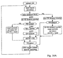
- the feeding rate of the remote cable feeding mechanism 62 is synchronized with the feeding rate of the local cable feeding mechanism 60 by conventional software, located in the ground operator station 6, which compares the speed signals returned by the respective encoders 86 and adjusts the speed of the respective drive motors 84 accordingly.
- the operation of this software is shown in the flow charts of Figures 16A and 16B.
- a tool 10 such as that described in copending U.S. Patent Application Serial No. 08/193,412 requires electrical cables 26, to power the drill motor, lights and video camera 16; hydraulic fluid hoses 24 to drive the hydraulic systems used by the tool 10; and one or more sealant hoses 24 for effecting the repair of leaks.
- a platform 100 is welded or otherwise affixed to the turret floor, and equipment supplying the various wires 26 and hoses 24 (generally designated 102 in Figure 3) is secured to the platform 100 and rotates with the reel 32.
- the equipment 102 includes a nitrogen bottle 104 and tool control assembly 106, one or more sealant pump assembly/sealant reservoirs 108, and an electrical control enclosure 110 which contains all tool control interfaces, video camera interfaces and power supply interfaces.
- the tool 10 is attached to one end of the umbilical cable 20, and the other end of the umbilical cable 20 is attached to the floor of the turret reel 32 within or immediately adjacent to the annular channel 49 formed between the two fences 44, 46.
- the various wires 26 and hoses 24 contained within the umbilical cable 20 are connected directly to the fluid and power supplies 102 located on the platform 100. Since these rotate with the reel 32 as the cable 20 is dispensed, the problem of wires or hoses twisting during loading or unloading of the cable 20 is avoided.
- the operator station 6 is stationary and positioned at any convenient location near the turret assembly 30, and includes the control system for the power feeding mechanisms 60, 62 and a control panel 6b for controlling the various functions of the tool 10 as described in U.S. Patent Application No. 08/193,412.
- Figure 14 shows the control components of the turret control enclosure 110.
- a Motorola MC68HC11 based microcontroller card 130 activates the tool control and sealant pump solenoid valves 132, 133, tool motor power driver 134 and lighting system power supply 136.
- the microcontroller card 130 reads conventional tool control sensors, sealant pump sensors and the drill motor current monitoring signal, and communicates with the ground operator station 6 over an RS-232 serial line. All application-specific interfaces use conventional circuitry/software located in the electrical control enclosure 110.
- the controls for the ground operator station 6, shown in Figure 15, are similarly microcontroller based.
- the microcontroller 130 reads data from and writes data to interface circuitry contained in the control panel 6b. Specialized interfaces communicate with the turret station processor, read the status of all switches and dials, activate the LED indicators on the control panel 6b, and monitor and control the cable feeding mechanisms 60, 62 in real time.
- the cable tensioning mechanism 120 shown in Figure 6 is provided to make the necessary electrical connections between the electrical control enclosure 110 on the turret platform 100 and the ground operator station 6. This permits the electrical cable 112 to be wound around the turret shaft 38 as the umbilical cable 20 is loaded onto the reel 32, yet the electrical cable 112 remains taut as the umbilical cable 20 is dispensed from the reel 32.
- the turret end of the cable 112 extends down through the platform 100 and is wound around the turret shaft 38, as seen in Figure 2.
- the other end of the cable 112 connects to extension cables at a junction box 114 attached to one side of the turret base frame 35, which connect the cable 112 to the operator station 6.
- the cable 112 runs through a pulley 122 at the end of an arm 124 biased by a tension spring 126 attached to the frame 35 at 127.
- the arm 124 thus bears away from the turret shaft 38, supporting the cable 112 and keeping the cable 112 taut as it unwinds from the shaft 38 when the umbilical cable 20 is dispensed.
- the arm 124 yields and is drawn toward the turret shaft 38 by the tension created on the electrical cable 112 as it is wound onto the turret shaft 38.
- the maximum number of turns of the electrical cable 112 around the turret shaft 38 must therefore be at least the same as, and should preferably slightly exceed, the maximum number of turns of the umbilical cable 20 around the reel 32.
- the launch saddle 92 is fitted with a rubber gasket 99 beneath the base plate 96, to prevent leakage of gas between the launch saddle 92 and the pipe 2, and the saddle 92 is clamped to the pipe 2 by wrapping the chains 97 around the pipe and tightening the tensioning bolts 97a, as shown in Figure 13.
- each entry pipe 94 terminates at its upper end in a flange 94a provided with a pair of opposed pivoting bolts 160, seen in the uncoupled position on the left-hand pipe 94 and in the coupled position on the right-hand pipe 94.
- the adaptor plate 170 attached to each of the hole cutter adaptor 150 and the tool launch adaptor 90 has a configuration complimentary to the flange 94a and opposed slots 172 into which the bolts 160 swing, so that when the nuts 162 are tightened the adaptor plate 170 is securely engaged to the flange 94a and the hole cutter adaptor 150 or the tool launch adaptor 90, as the case may be, is properly aligned with the entry pipe 94.
- the hole cutter adapter 150 shown in Figure 12A, supporting a 3" carbide-tipped long-stroke hole cutter 152 with a cutting head 154, is thus attached to the launch saddle 92 by coupling the adaptor plate 170 to one of the entry pipes 94, swinging the bolts 160 into position in the slots 172 and tightening the nuts 162.
- a pneumatically driven drilling device (not shown) is engaged to the hole cutter 152 and activated to cut the 3" entry opening 4 through the pipe wall at 45 degrees (following the angle of the entry pipe 94).
- the hole cutter adaptor 150 is detached from the launch saddle 92 by loosening the nuts 162 and swinging away the bolts 160 to detach the adaptor plate 170.
- the tool launch adapter 90 as shown in Figure 12B a hollow pipe with a smooth interior and rounded lower edge which extends through the adaptor plate 170, is then coupled to the launch saddle 92 in similar fashion.
- the vane-type valve 93 is closed to prevent gas from escaping during this part of the procedure.
- the tool launch adapter 90 both protects the tool 10 during launching and withdrawal and its rounded lower edge protects the jacket 22 of the umbilical cable 20 from rubbing against the sharp edges of the entry opening 4.
- the exposed end 91 of the tool adapter 90 projects out of the entry pipe 94.
- the tool adapter 90 contains resilient umbilical cable seals 109 in the form of O-rings to prevent leakage of gas during the inspection/repair operation, and a limit switch 111 for reasons described below.
- the umbilical cable 20 is engaged into the local cable feeding mechanism 60 and the remote cable feeding mechanism 62 by removing the bolts 77, swinging the frame 74 open, laying the cable 20 over the lower set of feeding rollers 76, closing each frame 74 and replacing the bolts 77.
- the first end 70 of the remote cable feeding mechanism 62 is then inserted over the exposed end 91 of the tool launch adapter 90 and the bolts 65 are tightened to secure the remote cable feeding mechanism 62 in place.
- the system is powered up at the ground operator station 6, and the tool 10 is fed into the pipeline by activating the feeding mechanisms 60, 62.
- the operator controls the feeding rate and distance, guided by the video monitor 6a at the ground control station 6.
- the local and remote cable feeding mechanisms 60, 62 feed the cable 20 in unison, the operator determining how much slack (if any) is permitted between the cable feeding mechanisms 60, 62.
- the local cable feeding mechanism 60 draws the cable off of the turret 30, the reel 32 rotates and the electrical cable 112 unwinds from the turret shaft 38, kept taut by the tensioning arm 124.
- the tool 10 may be fed further down the pipeline 2 for additional inspection or repairs, or may be withdrawn from the pipeline 2.
- the operator reverses the feeding direction of the feeding mechanisms 60, 62.
- the umbilical cable 20 is withdrawn from the pipe 2 by the remote cable feeding mechanism 62 and loaded onto the turret 30 by the local cable feeding mechanism 60.
- the electrical cable 112 winds onto the turret shaft 38 and the tensioning arm 124 is drawn toward the turret shaft 38.
- Each successive layer of umbilical cable 20 falls into the channel 49 formed between the fences 44, 46 and lays on top of the previous layer, until the tool 10 hits the limit switch 111 in the tool launch adapter 90, which automatically shuts off the cable feeding mechanisms 60, 62.
- the operator then detaches the remote cable feeding mechanism 62 from the tool launch adapter 90 and uncouples the adaptor plate 170 from the flange 94a, thus detaching the tool launch adaptor 90 from the launch saddle 92.
- the tool 10 remains in the tool launch adaptor 90 where it is stored for future use.
- the remaining length of umbilical cord 20 can be fed onto the turret 30 by the local cable feeding mechanism 60 or by hand.
- the entry opening 4 is sealed in a conventional fashion, and the launch saddle 92 and gasket 99 are removed from the pipeline 2 followed by backfilling over the pipeline 2 if necessary.
Landscapes
- Engineering & Computer Science (AREA)
- General Engineering & Computer Science (AREA)
- Chemical & Material Sciences (AREA)
- Combustion & Propulsion (AREA)
- Mechanical Engineering (AREA)
- Laying Of Electric Cables Or Lines Outside (AREA)
- Unwinding Of Filamentary Materials (AREA)
- Light Guides In General And Applications Therefor (AREA)
Abstract
Description
- This invention relates to a cable feeding system for feeding a cable through a conduit. In particular, this invention relates to a system for feeding a cable through a pipeline at a controlled rate over controlled distances, and an umbilical cable therefor for use with pipe inspecting or repairing tools.
- Devices which inspect and/or repair pipes internally are becoming more popular as an alternative to excavation, which can be costly, inconvenient and impractical. For example, such a device is disclosed in copending U.S. Patent Application Serial No. 08/193,412 filed February 7, 1994, which is incorporated herein by reference. The device includes a tool having a body supporting a working head and a video camera, which is fed through a pipeline to locate and repair leaking joints.
- The tool is fed through a pipeline attached to the end of an umbilical cable, which contains the required wires and hoses that enable the tool to perform its various functions, the other end of which is connected to a master control station/operator interface panel located outside of the pipeline. The umbilical cable thus functions to both move the device along the pipeline and provide protection for the various electrical wires and fluid hoses, including hydraulic lines, required by the tool.
- To efficiently operate such a tool, the umbilical cable must be fed into the pipeline in a controlled fashion, which allows the operator to know the approximate position of the tool within the pipe at any particular point in time and to thus locate pipe joints with minimal difficulty. The length of the cable can be 50 metres or longer, and its weight is significant because the cable contains all electrical wires and fluid hoses required by the tool, so manually feeding the tool through a pipeline can be difficult and inefficient. A mechanical feeding system provides a viable alternative, but any such system must feed the cable consistently and uniformly. To keep costs within reason the feeding system cannot be designed to recognize when the cable is not feeding properly and to respond accordingly as a person would.
- Moreover, it is frequently impractical to dispense the cable immediately adjacent to the pipeline, especially where excavation is required to reach the pipeline. The cable unloading system must therefore be able to operate at a reasonable distance from the pipeline while the feeding system accurately feeds the cable into a small entrance opening, without the cable buckling or bunching up.
- The umbilical cable itself must be flexible enough to bend around corners, particularly at the entrance opening to the pipeline which will usually be drilled through the side wall of the pipe. However, since the tool is not self-propelled, to stay within size and cost constraints, the cable must also be stiff enough that it does not compress, coil or bunch up inside the pipeline as the tool is being pushed along.
- The umbilical cable jacket should be as light as possible, to minimize friction against the pipe interior, but it must be robust enough to protect the relatively delicate electrical wires and fluid lines contained within it. Because the cable must be long enough to feed through the pipeline over relatively large distances, in order to minimize the need to excavate to drill entry openings, it must be stored on a reel. However, it is important that the cable not retain the shape of the storage reel when unrolled, as this would increase friction against the pipe and increase opportunities for coiling or bunching up within the pipe.
- Many of these design parameters are conflicting, which presents a considerable problem in the design of an efficient umbilical cable for a tool of this nature.
- The design of a storage reel also presents difficulties, because of the electrical and fluid lines required by the tool. For the tool to operate as it is being drawn off of the reel, electrical, gas and hydraulic fluid supplies must remain connected to the tool through the umbilical cable, even as the reel rotates. But to connect these supplies through the revolute joint of the reel is difficult and costly.
- The present invention overcomes these problems by providing a feeding system for feeding a cable through a conduit, comprising a revolving turret having a reel on which the cable is stored. Attached to the base of the turret is a local cable feeding mechanism which feeds the cable to a remote cable feeding mechanism attached to a launch saddle affixed over an entry opening drilled into the conduit. The feeding rollers within each feeding mechanism are synchronized by drive chains and spur gears, and the two feeding mechanisms are synchronized with each other using encoders which monitor and measure the length of cable passing through each feeding mechanism and adjust the relative feeding rate of each feeding mechanism to compensate for any difference. This ensures consistent, uniform feeding of the cable through the conduit, even when the turret is positioned at a considerable distance from the conduit.
- Most of the equipment and controls supplying fluids and electrical power through the cable are mounted on the reel itself, which avoids routing fluid hoses and wires through the revolute joint of the turret. An electrical cable containing electrical wires for both supplying power to the controls and equipment mounted on the reel and delivering signals to a stationary operator station, is wound around the turret shaft as the reel is loaded, and kept taut by a tensioning mechanism as the umbilical cable is dispensed from the reel, to avoid the need for slip rings.
- The umbilical cable preferably comprises a non-braided polyethylene hose containing a solid pultruded fibreglass rod which prevents the hose from buckling or bunching up, but is sufficiently flexible to bend around corners in the pipe and ensure uniform feeding.
- This feeding system is particularly useful for feeding through a pipeline an umbilical cable containing wires and/or hoses connecting a device, for example a tool for inspecting or repairing pipes, to an operator control station located outside of the pipeline. However, the invention may be used to feed any semi-rigid cable, hose, pipe, wire etc. through any type of conduit.
- The present invention thus provides a cable feeding system for feeding a cable through a conduit, comprising a turret having a base and a reel rotatably mounted on the base, a local cable feeding mechanism mounted in a stationary position relative to the base for drawing the cable off of the reel, and a remote cable feeding mechanism spaced from the local cable feeding mechanism for feeding the cable into an opening in the conduit, whereby the local cable feeding mechanism and the remote cable feeding mechanism are synchronized to feed the cable at the same rate relative to one another.
- The present invention further provides a cable containing wires and/or hoses connecting a device for use inside a conduit to an operator station located outside of the conduit, the cable comprising a jacket formed from flexible hose to protect the electrical wires and fluid hoses, and a stiffening rod extending through substantially the length of the cable to provide stiffness in the cable and thereby prevent the cable from buckling or bunching up in the conduit.
- In drawings which illustrate by way of example only a preferred embodiment of the invention,
- Figure 1 is a schematic view of a pipe repairing device utilizing the umbilical cable of the invention,
- Figure 2 is a side elevation of the feeding system of the invention,
- Figure 3 is a perspective view of the turret for the cable feeding system of Figure 2,
- Figure 4 is a top plan view of the reel for the turret of Figure 3,
- Figure 5 is a partially cutaway side elevation of the turret of Figure 3,
- Figure 6 is a top plan view of the base of the turret of Figure 3,
- Figure 7 is a side elevation of the launch saddle showing the remote cable feeding mechanism attached,
- Figure 8 is a perspective view of the local cable feeding mechanism,
- Figure 9 is an end elevation of the feeding mechanism of Figure 8,
- Figure 10 is a cross-section of the feeding mechanism of Figure 8,
- Figure 11 is a top plan view showing the roller arrangement in the feeding mechanism of Figure 8,
- Figure 12A is a cross-section of the launch saddle affixed to a pipe with the hole cutter adaptor attached,
- Figure 12B is a cross-section of the launch saddle affixed to a pipe with the tool launch adaptor attached,
- Figure 13 is a cross-section of the pipeline with the launch saddle attached,
- Figure 14 is a block diagram showing the components of the turret control station,
- Figure 15 is a block diagram showing the components of the ground operator station and control panel,
- Figures 16A and 16B are flow charts showing the operation of the operator station software, and
- Figure 17 is a cross-section of the umbilical cable.
- Figure 1 schematically illustrates the pipe repairing device disclosed and claimed in copending Canadian Patent Application No. 2,111,876 filed on December 20, 1993. The
tool 10 comprises abody 12 having a pivotable workinghead 14 for drilling into the wall of acast iron pipe 2 at a bell andspigot pipe joint 3 and injecting a sealant into the space between the bell and the spigot, to repair any leaks at thejoint 3. Aground operator station 6 having avideo monitor 6a and acontrol panel 6b controls the various electrical functions of thetool 10, including aminiature video camera 16 mounted on the tool body, and also controls fluid sources for a sealant pump system and hydraulic pivoting and drillhead mechanisms, as further described below. The pipe repairing device is fully described in Canadian Patent Application No. 2,111,876. - The
umbilical cable 20 contains allhoses 24 andelectrical wires 26 which enable the tool to perform its functions. Theumbilical cable 20, shown in cross-section in Figure 17, comprises ajacket 22 formed from 1.25" OD/1" ID non-braided clear polyethylene hose which is smooth, flexible and sufficiently thick to protect thefluid hoses 24 andelectrical wires 26 contained within it. A 3/8"pultruded fibreglass rod 28 extends through substantially the length of thecable 20, to provide sufficient stiffness in thecable 20 to prevent buckling or bunching up in thepipe 2, while allowing sufficient flexibility to allow thecable 20 to bend at the pipe entrance (as seen in Figure 12B) and around any corners or bends within thepipeline 2. - The cable feeding system of the invention, suitable for feeding a cable such as the
umbilical cable 20 through a pipeline or other conduit, is illustrated in Figure 2. The system includes aturret 30 comprising a rotatingreel 32 mounted on abase 34, a localcable feeding mechanism 60 mounted on apost 61 affixed to thebase 34 and a remotecable feeding mechanism 62 for attachment to the entry opening 4 in thepipe 2 in the manner described below. - The
base 34 of theturret 30 has aframe 35 composed of metal tubing, preferably rectangular tubing to facilitate the attachment of turret components, withlegs 36 relatively uniformly disposed about theframe 35 to raise the frame slightly (which can be advantageous on rough or uneven ground) and spaced apart sufficiently to ensure stability when thereel 32 is in motion. Theturret reel 32 is rotatably mounted on aturret shaft 38 about generally the centre of the base 34 so that thereel 32 rotates freely on thebase 34. For theumbilical cable 20 described above the minimum reel diameter should be approximately six feet (1.8 m); more flexible cables will permit asmaller reel 32 to be used. - The
reel 32, best seen in Figures 3 to 5, may be formed from metal tubing, preferably cylindrical tubing to minimize the contact area between thereel 32 and thecable 20 and thus minimize friction when thecable 20 is being loaded onto the reel or dispensed therefrom, and without any sharp corners on which thecable 20 could snag. Radial spokes 40 (seen in Figure 4) extend from acentral hub 42 supported by theturret shaft 38 and form an open floor for thereel 32. - The
spokes 40 support inner andouter fences tubular posts 48 extending generally orthogonally to thespokes 40 and welded or otherwise affixed thereto. Eachfence top rail posts 48, to maintain both the spacing between and the generally vertical orientation of theposts 48, and to provide a smooth surface for the loading and dispensing of thecable 20. - The
fences cable 20, as seen in Figure 4, but in any event less than two cable diameters, forming anannular channel 49 into which thecable 20 is loaded. This ensures that as thecable 20 is loaded onto thereel 32 it will overlay itself only axially relative to thereel 32, as shown in Figure 5, not radially, to prevent thecable 20 from entangling or interfering with underlying cable layers as it is being dispensed from thereel 32. Thus, as thecable 20 is loaded onto thereel 32 each successive layer falls on top of the previous cable layer, and as such when dispensed the uppermost layer ofcable 20 is always unobstructed. - The
cable 20 is dispensed and loaded onto thereel 32 by a localcable feeding mechanism 60 mounted on apost 61 welded or otherwise affixed to theturret base 34 at a level slightly higher than thetop rails cable feeding mechanism 60 has afirst end 70 and asecond end 72, and is mounted at an attitude such that thefirst end 70 faces slightly downwardly toward thereel 32, as shown in Figure 5, to minimize bending of thecable 20 as it is dispensed. The localcable feeding mechanism 60 may if desired be adjustably mounted, to allow for adjustment of its direction and attitude relative to thereel 32. - The local
cable feeding mechanism 60, illustrated in detail in Figures 8 to 11, comprises a hingedframe 74 containing parallel sets of upper andlower feeding rollers 76 mounted onroller shafts 73 supported by theframe 74. The upper and lower sets ofrollers 76 are spaced apart a distance approximately equal to the diameter of thecable 20, to provide a frictional engagement between therollers 76 and thejacket 22 of thecable 20 without deteriorating thecable jacket 22. Therollers 76 are thus preferably composed of rubber or a similar resilient material which provides good frictional engagement, or may be metal or plastic rollers provided with a resilient frictional surface such as rubber to engage thecable jacket 22 during dispensing and loading operations. Theframe 74 is hinged at 75 and removable securing means such as bolts 77 (seen in Figure 9) are provided, so that theframe 74 can be swung open for insertion of thecable 20 and then locked closed for use. - The feeding
rollers 76 within each set are aligned in the direction of feeding. As seen in Figures 8 and 11, in both the upper and lower sets ofrollers 76 eachend roller 76a is provided with asprocket 79 and themiddle roller 76b is provided with twosprockets 79, the feedingrollers 76 of each set being thereby interconnected bytransmission chains 80 with theother rollers 76 of the same set, so that their rates of rotation are synchronized. The lower set ofrollers 76 is in turn synchronized with the upper set ofrollers 76 byspur gears 82 meshing between oneroller 76 of each set, being themiddle roller 76b in the preferred embodiment illustrated. A suitable electric motor or other drive means, in the embodiment illustrated aDC servo motor 84 coupled to agearbox 85, drives one of therollers 76 of the lower set directly, and theother rollers 76 in the lower set are driven by thetransmission chains 80. The upper set ofrollers 76 is in turn driven at the same rate, in the opposite direction, by the meshing of the spur gears 82. It will be appreciated that it is immaterial whichroller 76 is driven by themotor 84, or whichroller 76 is provided with aspur gear 82 so long as thesame roller 76 of the other set is so equipped. - Attached to the
frame 74 is means for measuring the cable length, comprising an incrementaloptical encoder 86 mounted in analuminum enclosure 87 with a free-wheeling rubber or rubber-edgedwheel 88 that engages thecable 20 just beyond thesecond end 72 of the localcable feeding mechanism 60. Thewheel 88 turns as thecable 20 passes through thesecond end 72, and the length ofcable 20 passing through the localcable feeding mechanism 60 is thus measured by theoptical encoder 86. A biasingroller 89 affixed to theframe 74 serves to ensure good frictional engagement between thewheel 88 and thecable jacket 22. The measuring means enables accurate power insertion and synchronization of the feeding rates as between the local and remotecable feeding mechanisms - The remote
cable feeding mechanism 62 is mounted on the end of a tool launch adapter 90, shown in Figures 7 and 12, attached to thelaunch saddle 92 which is clamped to thepipe 2 before the entry opening 4 is drilled, as described below. Thelaunch saddle 92 comprises at least oneentry pipe 94 welded or otherwise affixed to abase plate 96, preferably at approximately a 45 degree angle relative to thebase plate 96. Theentry pipe 94 contains a conventional 3" medium pressure vane-type valve 93 (see Figure 7) for closing off theentry pipe 94. Thehole cutter adaptor 150, for engaging a drilling mechanism to cut the entry opening 4 (see Figure 12A), and the tool launch adaptor 90, for engaging the remotecable feeding mechanism 62 to thelaunch saddle 92 for feeding thecable 20 into the pipeline 2 (see Figure 12B), are each provided with anadaptor plate 170, for alternately attaching thehole cutter adaptor 150 or the tool launch adaptor 90 to thelaunch saddle 92, as described below. - A pair of
chains 97 secured to tensioning bolts 97a clamps thebase plate 96 to thepipe 2, as seen in Figure 13, usually in an upright orientation but circumstances may dictate otherwise. Preferably thelaunch saddle 92 is provided with two oppositely-directedentry pipes 94 which may be reinforced by a brace 92a extending therebetween, as in the example illustrated in Figures 7 and 12, which allows repair operations to be effected in either direction along thepipeline 2 without reorienting thelaunch saddle 92. - The remote
cable feeding mechanism 62, illustrated in Figure 7, is essentially identical to the localcable feeding mechanism 60. Itsfirst end 70 serves as a receptacle which slips over the exposedend 91 of the tool launch adapter 90 as shown in Figures 7 and 12B, and thebolts 65 at thefirst end 70 of theframe 74 are tightened to engage the remotecable feeding mechanism 62 to the tool launch adapter 90. Theadaptor plate 170 of the tool launch adapter 90 is in turn coupled to theflange 94a of theentry pipe 94 such that the remotecable feeding mechanism 62 is in direct alignment with the entry opening 4. The remotecable feeding mechanism 62 is provided with anoptical encoder 86 affixed to theframe 74 just beyond thesecond end 72 of the remotecable feeding mechanism 62, as in the localcable feeding mechanism 60, to measure thecable 20 as it enters the remotecable feeding mechanism 62 and is fed into thepipeline 2. - The feeding rate of the remote
cable feeding mechanism 62 is synchronized with the feeding rate of the localcable feeding mechanism 60 by conventional software, located in theground operator station 6, which compares the speed signals returned by therespective encoders 86 and adjusts the speed of therespective drive motors 84 accordingly. The operation of this software is shown in the flow charts of Figures 16A and 16B. - A
tool 10 such as that described in copending U.S. Patent Application Serial No. 08/193,412 requireselectrical cables 26, to power the drill motor, lights andvideo camera 16;hydraulic fluid hoses 24 to drive the hydraulic systems used by thetool 10; and one ormore sealant hoses 24 for effecting the repair of leaks. To avoid routing thevarious wires 26 andhoses 24 through the revolute joint of theturret 30, aplatform 100 is welded or otherwise affixed to the turret floor, and equipment supplying thevarious wires 26 and hoses 24 (generally designated 102 in Figure 3) is secured to theplatform 100 and rotates with thereel 32. For thepipe repair tool 10 referred to above theequipment 102 includes anitrogen bottle 104 andtool control assembly 106, one or more sealant pump assembly/sealant reservoirs 108, and anelectrical control enclosure 110 which contains all tool control interfaces, video camera interfaces and power supply interfaces. - Thus, the
tool 10 is attached to one end of theumbilical cable 20, and the other end of theumbilical cable 20 is attached to the floor of theturret reel 32 within or immediately adjacent to theannular channel 49 formed between the twofences various wires 26 andhoses 24 contained within theumbilical cable 20 are connected directly to the fluid andpower supplies 102 located on theplatform 100. Since these rotate with thereel 32 as thecable 20 is dispensed, the problem of wires or hoses twisting during loading or unloading of thecable 20 is avoided. - Electrical power is supplied to a turret control station on the
platform 100, contained inelectrical control enclosure 110, and signals are supplied therefrom to theground operator station 6, through anelectrical cable 112, shown in Figures 5 and 6, which contains all AC power lines, serial communication lines and acoaxial video cable 6c. Theoperator station 6 is stationary and positioned at any convenient location near theturret assembly 30, and includes the control system for thepower feeding mechanisms control panel 6b for controlling the various functions of thetool 10 as described in U.S. Patent Application No. 08/193,412. - Figure 14 shows the control components of the
turret control enclosure 110. A Motorola MC68HC11 basedmicrocontroller card 130 activates the tool control and sealantpump solenoid valves motor power driver 134 and lightingsystem power supply 136. Themicrocontroller card 130 reads conventional tool control sensors, sealant pump sensors and the drill motor current monitoring signal, and communicates with theground operator station 6 over an RS-232 serial line. All application-specific interfaces use conventional circuitry/software located in theelectrical control enclosure 110. - The controls for the
ground operator station 6, shown in Figure 15, are similarly microcontroller based. Themicrocontroller 130 reads data from and writes data to interface circuitry contained in thecontrol panel 6b. Specialized interfaces communicate with the turret station processor, read the status of all switches and dials, activate the LED indicators on thecontrol panel 6b, and monitor and control thecable feeding mechanisms - To avoid using slip rings, which tend to be expensive and unreliable in many situations, the
cable tensioning mechanism 120 shown in Figure 6 is provided to make the necessary electrical connections between theelectrical control enclosure 110 on theturret platform 100 and theground operator station 6. This permits theelectrical cable 112 to be wound around theturret shaft 38 as theumbilical cable 20 is loaded onto thereel 32, yet theelectrical cable 112 remains taut as theumbilical cable 20 is dispensed from thereel 32. The turret end of thecable 112 extends down through theplatform 100 and is wound around theturret shaft 38, as seen in Figure 2. The other end of thecable 112 connects to extension cables at ajunction box 114 attached to one side of theturret base frame 35, which connect thecable 112 to theoperator station 6. - As best seen in Figure 6, between the
turret shaft 38 and thejunction box 114 thecable 112 runs through apulley 122 at the end of anarm 124 biased by atension spring 126 attached to theframe 35 at 127. Thearm 124 thus bears away from theturret shaft 38, supporting thecable 112 and keeping thecable 112 taut as it unwinds from theshaft 38 when theumbilical cable 20 is dispensed. When thetool 10 is being withdrawn from thepipeline 2 and theumbilical cable 20 is being loaded back onto thereel 32, thearm 124 yields and is drawn toward theturret shaft 38 by the tension created on theelectrical cable 112 as it is wound onto theturret shaft 38. The maximum number of turns of theelectrical cable 112 around theturret shaft 38 must therefore be at least the same as, and should preferably slightly exceed, the maximum number of turns of theumbilical cable 20 around thereel 32. - In operation, a portion of the
pipeline 2 to be inspected or repaired is exposed. Thelaunch saddle 92 is fitted with arubber gasket 99 beneath thebase plate 96, to prevent leakage of gas between thelaunch saddle 92 and thepipe 2, and thesaddle 92 is clamped to thepipe 2 by wrapping thechains 97 around the pipe and tightening the tensioning bolts 97a, as shown in Figure 13. - As can be seen in Figures 12A and 12B, to facilitate attachment and removal of the
hole cutter adaptor 150 and the tool launch adaptor 90 eachentry pipe 94 terminates at its upper end in aflange 94a provided with a pair of opposed pivotingbolts 160, seen in the uncoupled position on the left-hand pipe 94 and in the coupled position on the right-hand pipe 94. Theadaptor plate 170 attached to each of thehole cutter adaptor 150 and the tool launch adaptor 90 has a configuration complimentary to theflange 94a andopposed slots 172 into which thebolts 160 swing, so that when the nuts 162 are tightened theadaptor plate 170 is securely engaged to theflange 94a and thehole cutter adaptor 150 or the tool launch adaptor 90, as the case may be, is properly aligned with theentry pipe 94. - The
hole cutter adapter 150, shown in Figure 12A, supporting a 3" carbide-tipped long-stroke hole cutter 152 with a cuttinghead 154, is thus attached to thelaunch saddle 92 by coupling theadaptor plate 170 to one of theentry pipes 94, swinging thebolts 160 into position in theslots 172 and tightening the nuts 162. A pneumatically driven drilling device (not shown) is engaged to thehole cutter 152 and activated to cut the 3" entry opening 4 through the pipe wall at 45 degrees (following the angle of the entry pipe 94). - Once the entry opening 4 has been drilled the
hole cutter adaptor 150 is detached from thelaunch saddle 92 by loosening thenuts 162 and swinging away thebolts 160 to detach theadaptor plate 170. The tool launch adapter 90, as shown in Figure 12B a hollow pipe with a smooth interior and rounded lower edge which extends through theadaptor plate 170, is then coupled to thelaunch saddle 92 in similar fashion. The vane-type valve 93 is closed to prevent gas from escaping during this part of the procedure. - The tool launch adapter 90 both protects the
tool 10 during launching and withdrawal and its rounded lower edge protects thejacket 22 of theumbilical cable 20 from rubbing against the sharp edges of the entry opening 4. The exposedend 91 of the tool adapter 90 projects out of theentry pipe 94. As seen in Figure 12B, the tool adapter 90 contains resilient umbilical cable seals 109 in the form of O-rings to prevent leakage of gas during the inspection/repair operation, and a limit switch 111 for reasons described below. - The
umbilical cable 20 is engaged into the localcable feeding mechanism 60 and the remotecable feeding mechanism 62 by removing thebolts 77, swinging theframe 74 open, laying thecable 20 over the lower set of feedingrollers 76, closing eachframe 74 and replacing thebolts 77. Thefirst end 70 of the remotecable feeding mechanism 62 is then inserted over the exposedend 91 of the tool launch adapter 90 and thebolts 65 are tightened to secure the remotecable feeding mechanism 62 in place. - The system is powered up at the
ground operator station 6, and thetool 10 is fed into the pipeline by activating the feedingmechanisms video monitor 6a at theground control station 6. The local and remotecable feeding mechanisms cable 20 in unison, the operator determining how much slack (if any) is permitted between thecable feeding mechanisms cable feeding mechanism 60 draws the cable off of theturret 30, thereel 32 rotates and theelectrical cable 112 unwinds from theturret shaft 38, kept taut by thetensioning arm 124. The operator stops the feedingmechanisms pipeline 2, activating the appropriate functions of thetool 10 as required. When the operation is complete, thetool 10 may be fed further down thepipeline 2 for additional inspection or repairs, or may be withdrawn from thepipeline 2. - To withdraw the
tool 10 from thepipeline 2, the operator reverses the feeding direction of the feedingmechanisms umbilical cable 20 is withdrawn from thepipe 2 by the remotecable feeding mechanism 62 and loaded onto theturret 30 by the localcable feeding mechanism 60. As theturret reel 32 rotates under the force of theumbilical cable 20 being fed onto thereel 32, theelectrical cable 112 winds onto theturret shaft 38 and thetensioning arm 124 is drawn toward theturret shaft 38. Each successive layer ofumbilical cable 20 falls into thechannel 49 formed between thefences tool 10 hits the limit switch 111 in the tool launch adapter 90, which automatically shuts off thecable feeding mechanisms cable feeding mechanism 62 from the tool launch adapter 90 and uncouples theadaptor plate 170 from theflange 94a, thus detaching the tool launch adaptor 90 from thelaunch saddle 92. - The
tool 10 remains in the tool launch adaptor 90 where it is stored for future use. The remaining length ofumbilical cord 20 can be fed onto theturret 30 by the localcable feeding mechanism 60 or by hand. The entry opening 4 is sealed in a conventional fashion, and thelaunch saddle 92 andgasket 99 are removed from thepipeline 2 followed by backfilling over thepipeline 2 if necessary. - The invention having been thus described by way of example only, it will be apparent to those skilled in the art that certain modifications and adaptations may be made without departing from the scope of invention, as set out in the appended claims. It will further be apparent that although the invention has been described using the example of an umbilical cable for an internal pipe repair tool, the invention can be adapted to feed any semi-rigid cable, wire, pipe, hose etc. into a conduit of any type, and the invention is in no way limited to the specific examples given herein.
Claims (20)
- A cable feeding system for feeding a cable through a conduit, comprisinga turret having a base and a reel rotatably mounted on the base,a local cable feeding mechanism mounted in a stationary position relative to the base for drawing the cable off of the reel, anda remote cable feeding mechanism spaced from the local cable feeding mechanism for feeding the cable into an opening in the conduit,whereby the local cable feeding mechanism and the remote cable feeding mechanism are synchronized to feed the cable at the same rate relative to one another.
- The cable feeding system of claim 1 wherein the local cable feeding mechanism is attached to the turret.
- The cable feeding system of daim 1 wherein the remote cable feeding mechanism is attached to the conduit.
- The cable feeding system of daim 1, 2 or 3 wherein the turret reel is mounted on a turret shaft and equipment or controls or both are mounted on the reel, and an electrical cable connecting a stationary operator station to the equipment or controls is wound around the turret shaft.
- The cable feeding system of claim 4 wherein a tensioning arm tensions the electric cable as it unwinds from the turret shaft.
- The cable feeding system of daim 1, 2 or 3 wherein the reel comprises inner and outer fences which are concentric and spaced apart a distance greater than a diameter of the cable but less than two diameters of the cable, the cable being loaded onto the reel into a channel formed between the two fences.
- The cable feeding system of claim 6 wherein the reel is formed from metal tubing.
- The cable feeding system of claim 1, 2 or 3 whereby the remote cable feeding mechanism is secured to a saddle connected to an entry opening of the conduit.
- The cable feeding system of claim 1, 2 or 3 wherein each feeding mechanism comprises two parallel sets of aligned rollers spaced apart a distance approximately equal to a diameter of the cable, to frictionally engage the cable and thereby draw the cable between the two sets of rollers.
- The cable feeding system of claim 9 wherein the rollers within each set of rollers are synchronized by one or more transmission chains driving sprockets affixed to each roller.
- The cable feeding system of claim 10 wherein the sets of rollers are synchronized with each other by gears affixed to at least one roller of each set.
- The cable feeding system of claim 10 wherein the rollers are driven by a motor.
- The cable feeding system of claim 12 wherein the local cable feeding mechanism and the remote cable feeding mechanism are synchronized to feed the cable at the same rate.
- The cable feeding system of claim 13 wherein each feeding mechanism is provided with an encoder having a wheel bearing against the cable, which measures the cable drawn through the feeding mechanism, and the cable feeding system is provided with means for comparing a length of cable measured by each encoder and adjusting a feeding rate of one or both feeding mechanisms so that both feeding mechanism feed the cable at the same rate.
- The cable feeding system of claim 1, 2 or 3 wherein the cable contains electrical wires or fluid hoses or both.
- The cable feeding system of claim 15 wherein one end of the cable is connected to a tool for inspecting or repairing a conduit.
- The cable feeding system of claim 16 in which the conduit is a gas pipeline.
- A cable containing wires and/or hoses connecting a device for use inside a conduit to an operator station located outside of the conduit, the cable comprising a jacket formed from flexible hose to protect the wires and hoses, and a stiffening rod extending through substantially the length of the cable to provide stiffness in the cable and thereby prevent the cable from buckling or bunching up in the conduit.
- The cable of claim 18 wherein the stiffening rod is a fibreglass rod.
- The cable of claim 18 or 19 wherein the jacket is formed from non-braided polyethylene.
Applications Claiming Priority (2)
| Application Number | Priority Date | Filing Date | Title |
|---|---|---|---|
| US503888 | 1995-07-18 | ||
| US08/503,888 US5681131A (en) | 1995-07-18 | 1995-07-18 | Cable feeding system and umbilical cable therefor |
Publications (3)
| Publication Number | Publication Date |
|---|---|
| EP0754902A2 true EP0754902A2 (en) | 1997-01-22 |
| EP0754902A3 EP0754902A3 (en) | 1998-12-02 |
| EP0754902B1 EP0754902B1 (en) | 2003-05-21 |
Family
ID=24003941
Family Applications (1)
| Application Number | Title | Priority Date | Filing Date |
|---|---|---|---|
| EP96304701A Expired - Lifetime EP0754902B1 (en) | 1995-07-18 | 1996-06-26 | Cable feeding system and umbilical cable therefor |
Country Status (4)
| Country | Link |
|---|---|
| US (1) | US5681131A (en) |
| EP (1) | EP0754902B1 (en) |
| CA (1) | CA2177127C (en) |
| DE (1) | DE69628241D1 (en) |
Cited By (6)
| Publication number | Priority date | Publication date | Assignee | Title |
|---|---|---|---|---|
| WO2000044506A1 (en) * | 1999-01-26 | 2000-08-03 | Dbs Beschichtung Und Systeme-Technik Gmbh | Method for coating the inside of pipes and coating system |
| EP1316381A1 (en) * | 2001-12-03 | 2003-06-04 | Mechafin AG | Wire-feeding device for a wire welding installation |
| FR2842883A1 (en) * | 2002-07-25 | 2004-01-30 | Elyo Cylergie | ROBOT FOR INSPECTING GALLERIES, ESPECIALLY HEAT NETWORKS |
| GB2401943A (en) * | 2000-11-29 | 2004-11-24 | Cooper Cameron Corp | Inspection and cleaning system pulled through a tubular by a wireline |
| US6959603B2 (en) | 2000-11-29 | 2005-11-01 | Cooper Cameron Corporation | Ultrasonic testing system and method |
| EP1855835A4 (en) * | 2005-02-28 | 2014-04-30 | Electric Power Res Inst | INSPECTION AND REPAIR PROCESS |
Families Citing this family (24)
| Publication number | Priority date | Publication date | Assignee | Title |
|---|---|---|---|---|
| CA2218436A1 (en) | 1997-10-15 | 1999-04-15 | Consolidated Edison Company Of New York, Inc. | Device for repairing pipes |
| US6073916A (en) * | 1998-10-08 | 2000-06-13 | Greenlee Textron Inc. | Powered cable feeding system |
| US6247664B1 (en) | 1999-06-25 | 2001-06-19 | Siecor Operations, Llc | Reel monitor devices and methods of using the same |
| EP1236254B1 (en) * | 1999-12-06 | 2003-12-03 | Pirelli General plc | Cable installation in ducting |
| US20010027695A1 (en) * | 2000-04-06 | 2001-10-11 | Lumpkin Wayne R. | Floating cable stop for a cable actuated bicycle component |
| US6370753B1 (en) | 2000-07-24 | 2002-04-16 | Arnco Corporation | Method and apparatus for wrapping and installing cable |
| US20020158239A1 (en) * | 2001-03-30 | 2002-10-31 | Nkf Kabel B.V. | Optical cable installation with mini-bend reduction |
| US20030226927A1 (en) * | 2002-06-06 | 2003-12-11 | Pieter Van Dine | Deployment arrangement for elongated flexible connecting members |
| US7025333B1 (en) * | 2004-12-20 | 2006-04-11 | Mark Delio Gianturco | Home navigation tool |
| KR100683132B1 (en) | 2005-09-29 | 2007-02-15 | 한국기초과학지원연구원 | Winding device of stranded conductor in pipe and winding method |
| US7376326B2 (en) * | 2006-07-20 | 2008-05-20 | Verizon New Jersey Inc. | Fiber optic cable stack measuring device |
| US20090084882A1 (en) * | 2007-09-27 | 2009-04-02 | Daniel Williams | Device and Method for Coiling a Flexible Material |
| BRPI0800473B1 (en) * | 2008-03-05 | 2020-04-22 | Petroleo Brasileiro Sa Petrobras | system and process for leak detection in umbilicals |
| WO2011103572A2 (en) * | 2010-02-22 | 2011-08-25 | Michael Mitrovich | Method and apparatus for applying variable rates of solid stick lubricant to the top of a rail |
| US8408520B2 (en) | 2010-04-26 | 2013-04-02 | Southwire Company | Apparatus for pushing conductors into conduit and other structures |
| US20140210989A1 (en) * | 2012-06-01 | 2014-07-31 | Mark S. Olsson | Systems and methods involving a smart cable storage drum and network node for transmission of data |
| US9656307B1 (en) * | 2015-11-12 | 2017-05-23 | Barry I. Blevins | Powered hose puller |
| US10481360B2 (en) * | 2016-11-16 | 2019-11-19 | Commscope Technologies Llc | Telecommunications cabling system |
| BR102018072062B1 (en) * | 2018-10-26 | 2023-12-12 | Universidade Federal Do Rio Grande Do Sul - Ufrgs | INTERVENTION TRACTOR SYSTEM COMPRISING AN UMBILICAL |
| US11415553B2 (en) * | 2019-07-23 | 2022-08-16 | The United States Of America, As Represented By The Secretary Of The Navy | Mobile automated non-destructive inspection system |
| CN113078584B (en) * | 2021-02-26 | 2022-09-16 | 广西电网有限责任公司柳州供电局 | Tightener for electric power engineering cable installation |
| CN113460813A (en) * | 2021-07-20 | 2021-10-01 | 江西清华泰豪三波电机有限公司 | Power output system |
| CN116281440B (en) * | 2023-03-30 | 2026-01-02 | 武汉船舶通信研究所(中国船舶集团有限公司第七二二研究所) | A system and control method for deploying and retrieving underwater measuring equipment for unmanned exploration vessels |
| CN116238970B (en) * | 2023-04-03 | 2025-08-05 | 中国人民解放军陆军勤务学院 | A soft pipeline operation vehicle |
Family Cites Families (15)
| Publication number | Priority date | Publication date | Assignee | Title |
|---|---|---|---|---|
| FR748949A (en) * | 1932-01-05 | 1933-07-13 | Handelm Nv | Multi-core cable |
| US3887163A (en) * | 1973-12-10 | 1975-06-03 | Rockwell International Corp | Apparatus for inserting cable or the like in conduits |
| DE2752072C2 (en) * | 1976-11-22 | 1983-03-03 | SIARGAS - Società Italiana Assistenza Reti Gas - S.p.A., Milano | Method and device for sealing leaky socket connections on pipelines, in particular on those laid underground |
| US4196307A (en) * | 1977-06-07 | 1980-04-01 | Custom Cable Company | Marine umbilical cable |
| DE2908351A1 (en) * | 1979-03-03 | 1980-09-11 | Franz Huettl Tv Rohrtechnik Gm | Inspection trolley for inspecting drains and pipes - has supply cable passing over speed-controlled winch and connecting it to surface vehicle |
| US4454999A (en) * | 1981-04-20 | 1984-06-19 | Woodruff Harold F | Cable dispensing device and method |
| JPS6044675A (en) * | 1983-08-20 | 1985-03-09 | 株式会社日立製作所 | Shifter in hollow bent piping and working method in piping using said shifter |
| AU572929B2 (en) * | 1984-12-14 | 1988-05-19 | Ka-Te System Ag | Apparatuas for carrying out repair work on a damaged pipe |
| US4905773A (en) * | 1987-11-02 | 1990-03-06 | Underground Technologies | Self-propelled subsoil penetrating tool system |
| EP0423443B1 (en) * | 1989-10-18 | 1994-09-28 | Ttc Technology Trading Company | Process and device for carrying-out the process to feed a cable into a cable manufacturing automaton |
| US5044824A (en) * | 1990-05-01 | 1991-09-03 | Long Technologies, Inc. | Method and apparatus for locating a service pipe outlet transversely connected to a lined main pipe |
| US5152506A (en) * | 1990-06-04 | 1992-10-06 | Pickrell John W | Apparatus for pulling cable |
| NL9001618A (en) * | 1990-07-17 | 1992-02-17 | Nederland Ptt | METHOD AND APPARATUS FOR INSTALLING A CABLE IN A CABLE PRODUCT. |
| US5139751A (en) * | 1990-09-07 | 1992-08-18 | Airrigation Engineering Co., Inc. | Apparatus for thrusting a hose along a conduit |
| US5527133A (en) * | 1994-08-17 | 1996-06-18 | Csillag; Robert | Tool for a sewer robot |
-
1995
- 1995-07-18 US US08/503,888 patent/US5681131A/en not_active Expired - Lifetime
-
1996
- 1996-05-22 CA CA002177127A patent/CA2177127C/en not_active Expired - Fee Related
- 1996-06-26 DE DE69628241T patent/DE69628241D1/en not_active Expired - Lifetime
- 1996-06-26 EP EP96304701A patent/EP0754902B1/en not_active Expired - Lifetime
Cited By (9)
| Publication number | Priority date | Publication date | Assignee | Title |
|---|---|---|---|---|
| WO2000044506A1 (en) * | 1999-01-26 | 2000-08-03 | Dbs Beschichtung Und Systeme-Technik Gmbh | Method for coating the inside of pipes and coating system |
| US6699324B1 (en) | 1999-01-26 | 2004-03-02 | Klaus Berdin | Method for coating the inside of pipes and coating system |
| GB2401943A (en) * | 2000-11-29 | 2004-11-24 | Cooper Cameron Corp | Inspection and cleaning system pulled through a tubular by a wireline |
| GB2401943B (en) * | 2000-11-29 | 2005-04-06 | Cooper Cameron Corp | Ultrasonic testing system and method |
| US6959603B2 (en) | 2000-11-29 | 2005-11-01 | Cooper Cameron Corporation | Ultrasonic testing system and method |
| EP1316381A1 (en) * | 2001-12-03 | 2003-06-04 | Mechafin AG | Wire-feeding device for a wire welding installation |
| FR2842883A1 (en) * | 2002-07-25 | 2004-01-30 | Elyo Cylergie | ROBOT FOR INSPECTING GALLERIES, ESPECIALLY HEAT NETWORKS |
| WO2004016981A1 (en) * | 2002-07-25 | 2004-02-26 | Elyo Cylergie | Gallery inspection robot |
| EP1855835A4 (en) * | 2005-02-28 | 2014-04-30 | Electric Power Res Inst | INSPECTION AND REPAIR PROCESS |
Also Published As
| Publication number | Publication date |
|---|---|
| CA2177127A1 (en) | 1997-01-19 |
| EP0754902A3 (en) | 1998-12-02 |
| DE69628241D1 (en) | 2003-06-26 |
| US5681131A (en) | 1997-10-28 |
| CA2177127C (en) | 1999-03-30 |
| EP0754902B1 (en) | 2003-05-21 |
Similar Documents
| Publication | Publication Date | Title |
|---|---|---|
| US5681131A (en) | Cable feeding system and umbilical cable therefor | |
| US6276398B1 (en) | Inflatable packer for repairing conduits | |
| RU2082909C1 (en) | Device for inspection of branching pipe line | |
| WO2011070353A2 (en) | Systems and methods for making pipe, and method of installing the pipe in a pipeline | |
| EP0750096B1 (en) | A method for injecting back-filling material into a space between the outside of double-wall pipes and the ground in the pipe-jacking method | |
| US11708932B2 (en) | Pipe lining preparation assembly | |
| US20150141190A1 (en) | Planetary Gear Assembly | |
| US5956135A (en) | Pipeline inspection apparatus | |
| US5273611A (en) | Apparatus for applying a continuous film to a pipeline | |
| FI93142C (en) | Equipment used for the renewal of pipelines, in particular sewer pipelines | |
| CA2798446C (en) | Method of inspecting and preparing a pipeline | |
| CA2218436A1 (en) | Device for repairing pipes | |
| CA1336544C (en) | Portable device for storing an endless metallic or fiber-optic cable | |
| US6726140B2 (en) | Take-up reel for flexible elongated members | |
| US2989980A (en) | Reel apparatus | |
| GB2057622A (en) | Pipe-line crawler | |
| KR200184453Y1 (en) | Cable reel for welding | |
| WO1993023729A1 (en) | Pipe testing and locating apparatus | |
| AU660183B2 (en) | Cable reeler | |
| CN221402748U (en) | Pipeline leakage detection device | |
| CA1288415C (en) | Pipe lining apparatus | |
| JPH04164507A (en) | Cutting device for blocking substance in pipeline and cutting and removal method of blocking substance in pipeline | |
| JP5346622B2 (en) | Water control body installation device and water control body installation method | |
| JP2580185Y2 (en) | Underground pipe burying equipment | |
| GB2531705A (en) | Apparatus and method |
Legal Events
| Date | Code | Title | Description |
|---|---|---|---|
| PUAI | Public reference made under article 153(3) epc to a published international application that has entered the european phase |
Free format text: ORIGINAL CODE: 0009012 |
|
| AK | Designated contracting states |
Kind code of ref document: A2 Designated state(s): BE DE FR GB IE IT NL |
|
| PUAL | Search report despatched |
Free format text: ORIGINAL CODE: 0009013 |
|
| AK | Designated contracting states |
Kind code of ref document: A3 Designated state(s): BE DE FR GB IE IT NL |
|
| 17P | Request for examination filed |
Effective date: 19990517 |
|
| 17Q | First examination report despatched |
Effective date: 20001219 |
|
| GRAH | Despatch of communication of intention to grant a patent |
Free format text: ORIGINAL CODE: EPIDOS IGRA |
|
| GRAH | Despatch of communication of intention to grant a patent |
Free format text: ORIGINAL CODE: EPIDOS IGRA |
|
| GRAA | (expected) grant |
Free format text: ORIGINAL CODE: 0009210 |
|
| AK | Designated contracting states |
Designated state(s): BE DE FR GB IE IT NL |
|
| PG25 | Lapsed in a contracting state [announced via postgrant information from national office to epo] |
Ref country code: NL Free format text: LAPSE BECAUSE OF FAILURE TO SUBMIT A TRANSLATION OF THE DESCRIPTION OR TO PAY THE FEE WITHIN THE PRESCRIBED TIME-LIMIT Effective date: 20030521 Ref country code: IT Free format text: LAPSE BECAUSE OF FAILURE TO SUBMIT A TRANSLATION OF THE DESCRIPTION OR TO PAY THE FEE WITHIN THE PRESCRIBED TIME-LIMIT;WARNING: LAPSES OF ITALIAN PATENTS WITH EFFECTIVE DATE BEFORE 2007 MAY HAVE OCCURRED AT ANY TIME BEFORE 2007. THE CORRECT EFFECTIVE DATE MAY BE DIFFERENT FROM THE ONE RECORDED. Effective date: 20030521 Ref country code: FR Free format text: LAPSE BECAUSE OF FAILURE TO SUBMIT A TRANSLATION OF THE DESCRIPTION OR TO PAY THE FEE WITHIN THE PRESCRIBED TIME-LIMIT Effective date: 20030521 Ref country code: BE Free format text: LAPSE BECAUSE OF FAILURE TO SUBMIT A TRANSLATION OF THE DESCRIPTION OR TO PAY THE FEE WITHIN THE PRESCRIBED TIME-LIMIT Effective date: 20030521 |
|
| REG | Reference to a national code |
Ref country code: GB Ref legal event code: FG4D |
|
| PGFP | Annual fee paid to national office [announced via postgrant information from national office to epo] |
Ref country code: GB Payment date: 20030611 Year of fee payment: 8 |
|
| REG | Reference to a national code |
Ref country code: IE Ref legal event code: FG4D |
|
| PG25 | Lapsed in a contracting state [announced via postgrant information from national office to epo] |
Ref country code: IE Free format text: LAPSE BECAUSE OF NON-PAYMENT OF DUE FEES Effective date: 20030626 |
|
| REF | Corresponds to: |
Ref document number: 69628241 Country of ref document: DE Date of ref document: 20030626 Kind code of ref document: P |
|
| PG25 | Lapsed in a contracting state [announced via postgrant information from national office to epo] |
Ref country code: DE Free format text: LAPSE BECAUSE OF FAILURE TO SUBMIT A TRANSLATION OF THE DESCRIPTION OR TO PAY THE FEE WITHIN THE PRESCRIBED TIME-LIMIT Effective date: 20030822 |
|
| NLV1 | Nl: lapsed or annulled due to failure to fulfill the requirements of art. 29p and 29m of the patents act | ||
| PLBE | No opposition filed within time limit |
Free format text: ORIGINAL CODE: 0009261 |
|
| STAA | Information on the status of an ep patent application or granted ep patent |
Free format text: STATUS: NO OPPOSITION FILED WITHIN TIME LIMIT |
|
| REG | Reference to a national code |
Ref country code: IE Ref legal event code: MM4A |
|
| 26N | No opposition filed |
Effective date: 20040224 |
|
| EN | Fr: translation not filed | ||
| PG25 | Lapsed in a contracting state [announced via postgrant information from national office to epo] |
Ref country code: GB Free format text: LAPSE BECAUSE OF NON-PAYMENT OF DUE FEES Effective date: 20040626 |
|
| GBPC | Gb: european patent ceased through non-payment of renewal fee |
Effective date: 20040626 |