EP0754860B1 - Oil-free scroll vacuum pump - Google Patents
Oil-free scroll vacuum pump Download PDFInfo
- Publication number
- EP0754860B1 EP0754860B1 EP96111523A EP96111523A EP0754860B1 EP 0754860 B1 EP0754860 B1 EP 0754860B1 EP 96111523 A EP96111523 A EP 96111523A EP 96111523 A EP96111523 A EP 96111523A EP 0754860 B1 EP0754860 B1 EP 0754860B1
- Authority
- EP
- European Patent Office
- Prior art keywords
- gas
- scroll
- revolving
- stationary
- lap
- Prior art date
- Legal status (The legal status is an assumption and is not a legal conclusion. Google has not performed a legal analysis and makes no representation as to the accuracy of the status listed.)
- Expired - Lifetime
Links
- 239000012530 fluid Substances 0.000 claims description 34
- 230000006835 compression Effects 0.000 claims description 17
- 238000007906 compression Methods 0.000 claims description 17
- XLYOFNOQVPJJNP-UHFFFAOYSA-N water Substances O XLYOFNOQVPJJNP-UHFFFAOYSA-N 0.000 description 36
- 238000004891 communication Methods 0.000 description 11
- 238000009833 condensation Methods 0.000 description 8
- 230000005494 condensation Effects 0.000 description 8
- 230000002093 peripheral effect Effects 0.000 description 6
- 238000004519 manufacturing process Methods 0.000 description 4
- 230000007246 mechanism Effects 0.000 description 4
- 239000007788 liquid Substances 0.000 description 3
- 230000006866 deterioration Effects 0.000 description 2
- YCKRFDGAMUMZLT-UHFFFAOYSA-N Fluorine atom Chemical compound [F] YCKRFDGAMUMZLT-UHFFFAOYSA-N 0.000 description 1
- 230000002159 abnormal effect Effects 0.000 description 1
- 238000009825 accumulation Methods 0.000 description 1
- 238000010420 art technique Methods 0.000 description 1
- 238000010276 construction Methods 0.000 description 1
- 238000001816 cooling Methods 0.000 description 1
- 230000002542 deteriorative effect Effects 0.000 description 1
- 238000007865 diluting Methods 0.000 description 1
- 238000001035 drying Methods 0.000 description 1
- 229910052731 fluorine Inorganic materials 0.000 description 1
- 239000011737 fluorine Substances 0.000 description 1
- 238000010438 heat treatment Methods 0.000 description 1
- 238000000034 method Methods 0.000 description 1
- 238000012856 packing Methods 0.000 description 1
- 230000002265 prevention Effects 0.000 description 1
- 230000001737 promoting effect Effects 0.000 description 1
- 238000005086 pumping Methods 0.000 description 1
- 239000011347 resin Substances 0.000 description 1
- 229920005989 resin Polymers 0.000 description 1
Images

Classifications
-
- F—MECHANICAL ENGINEERING; LIGHTING; HEATING; WEAPONS; BLASTING
- F04—POSITIVE - DISPLACEMENT MACHINES FOR LIQUIDS; PUMPS FOR LIQUIDS OR ELASTIC FLUIDS
- F04C—ROTARY-PISTON, OR OSCILLATING-PISTON, POSITIVE-DISPLACEMENT MACHINES FOR LIQUIDS; ROTARY-PISTON, OR OSCILLATING-PISTON, POSITIVE-DISPLACEMENT PUMPS
- F04C28/00—Control of, monitoring of, or safety arrangements for, pumps or pumping installations specially adapted for elastic fluids
- F04C28/28—Safety arrangements; Monitoring
-
- F—MECHANICAL ENGINEERING; LIGHTING; HEATING; WEAPONS; BLASTING
- F04—POSITIVE - DISPLACEMENT MACHINES FOR LIQUIDS; PUMPS FOR LIQUIDS OR ELASTIC FLUIDS
- F04C—ROTARY-PISTON, OR OSCILLATING-PISTON, POSITIVE-DISPLACEMENT MACHINES FOR LIQUIDS; ROTARY-PISTON, OR OSCILLATING-PISTON, POSITIVE-DISPLACEMENT PUMPS
- F04C18/00—Rotary-piston pumps specially adapted for elastic fluids
- F04C18/02—Rotary-piston pumps specially adapted for elastic fluids of arcuate-engagement type, i.e. with circular translatory movement of co-operating members, each member having the same number of teeth or tooth-equivalents
- F04C18/0207—Rotary-piston pumps specially adapted for elastic fluids of arcuate-engagement type, i.e. with circular translatory movement of co-operating members, each member having the same number of teeth or tooth-equivalents both members having co-operating elements in spiral form
- F04C18/0215—Rotary-piston pumps specially adapted for elastic fluids of arcuate-engagement type, i.e. with circular translatory movement of co-operating members, each member having the same number of teeth or tooth-equivalents both members having co-operating elements in spiral form where only one member is moving
- F04C18/0223—Rotary-piston pumps specially adapted for elastic fluids of arcuate-engagement type, i.e. with circular translatory movement of co-operating members, each member having the same number of teeth or tooth-equivalents both members having co-operating elements in spiral form where only one member is moving with symmetrical double wraps
-
- F—MECHANICAL ENGINEERING; LIGHTING; HEATING; WEAPONS; BLASTING
- F04—POSITIVE - DISPLACEMENT MACHINES FOR LIQUIDS; PUMPS FOR LIQUIDS OR ELASTIC FLUIDS
- F04C—ROTARY-PISTON, OR OSCILLATING-PISTON, POSITIVE-DISPLACEMENT MACHINES FOR LIQUIDS; ROTARY-PISTON, OR OSCILLATING-PISTON, POSITIVE-DISPLACEMENT PUMPS
- F04C2210/00—Fluid
- F04C2210/12—Fluid auxiliary
- F04C2210/122—Nitrogen (N2)
-
- F—MECHANICAL ENGINEERING; LIGHTING; HEATING; WEAPONS; BLASTING
- F04—POSITIVE - DISPLACEMENT MACHINES FOR LIQUIDS; PUMPS FOR LIQUIDS OR ELASTIC FLUIDS
- F04C—ROTARY-PISTON, OR OSCILLATING-PISTON, POSITIVE-DISPLACEMENT MACHINES FOR LIQUIDS; ROTARY-PISTON, OR OSCILLATING-PISTON, POSITIVE-DISPLACEMENT PUMPS
- F04C2220/00—Application
- F04C2220/10—Vacuum
- F04C2220/12—Dry running
-
- F—MECHANICAL ENGINEERING; LIGHTING; HEATING; WEAPONS; BLASTING
- F04—POSITIVE - DISPLACEMENT MACHINES FOR LIQUIDS; PUMPS FOR LIQUIDS OR ELASTIC FLUIDS
- F04C—ROTARY-PISTON, OR OSCILLATING-PISTON, POSITIVE-DISPLACEMENT MACHINES FOR LIQUIDS; ROTARY-PISTON, OR OSCILLATING-PISTON, POSITIVE-DISPLACEMENT PUMPS
- F04C2220/00—Application
- F04C2220/50—Pumps with means for introducing gas under pressure for ballasting
Definitions
- This invention relates to an oil-free scroll vacuum pump for compressing fluid with stationary and revolving scrolls and, more particularly, to oil-free scroll vacuum pump, in which gas is introduced into a sealed space defined by laps of the scrolls engaged with one another through a gas ballast gas inlet port formed in the stationary scroll, and compressed fluid in the sealed space is discharged together with the introduced gas to the outside.
- Fig. 7 shows a well-known scroll vacuum pump.
- This scroll vacuum pump comprises a main shaft 56, a revolving scroll 51 supported on a central crank portion 55a of the main shaft 56 and having revolving laps each formed on axial side, a pair of stationary scrolls 52A and 52B each having a stationary lap engaged with each revolving lap, and three eccentric rotatable shafts 53 disposed at a circumferential interval of 120° for rotation restriction.
- the stationary scrolls 52A and 52B are disc-like and form together a casing with their peripheral walls sealed together via an intervening seal member to define an inner sealed space. They have respective central holes 51a, through which the main shaft 56 is mounted via bearings. The main shaft 56 is thus supported rotatably by two-point support.
- the stationary scrolls 52A and 52B have respective spiral stationary laps 50, which are disposed symmetrically around such that they face each other.
- the stationary scroll 52A has a discharge port 57 and a withdrawal port 58, formed in its central portion and its outer periphery, respectively.
- the revolving scroll 51 has revolving laps 54 each formed on each axial side and capable of being engaged with each stationary lap 50.
- the eccentric rotatable shafts 53 are rotatably supported in peripheral portions of the revolving scroll 51.
- the eccentric rotatable shafts 53 each have opposite side portions rotatably supported in the stationary scrolls 52A and 52B for rotation restriction of the revolving scroll 51 by two-point support.
- Designated at 59A and 59B are tip seals fitted in the tips of the laps.
- eccentric rotatable motion of the eccentric shaft portion 55a is brought about to cause revolution of the revolving scroll 51 with a predetermined radius about the lap center of the stationary scrolls 52A and 52B while preventing the rotation of the revolving scroll 51.
- the gas withdrawn into the scroll vacuum pump may contain water vapor.
- the saturation vapor pressure is exceeded as a result of the compression of the gas containing water vapor, condensation and liquefaction of water vapor result, and sole compressed gas is discharged through the discharge port.
- the remaining water content is accumulated in a lower part of the discharge port in the final space defined by the revolving and stationary scrolls.
- a feature of the invention resides in an oil-free scroll vacuum pump for compressing fluid with revolving and stationary scrolls to discharge the compressed fluid to the outside, wherein:
- the ratio of the water vapor contained in the introduced gas is reduced. Also, the final sealed space is compressed to reduce the partial water vapor pressure when it is communicated with the discharge port to be below the saturation water vapor pressure of the scroll pump. The water vapor is thus discharged, without being liquified, through the discharge port while gassifying the water attached to the lap surfaces as a result of the condensation and liquefaction.
- three or more sealed spaces are formed in a preceding stage to the gas introduction sealed space for compressing fluid therein.
- Preferred embodiment of the invention resides in the oil-free scroll vacuum pump, wherein:
- the inlet port is held closed to prevent reverse flow of compressed fluid to the inlet port, thus allowing the compressed fluid to be discharged through the discharge passage to the outside.
- the reverse flow of the compressed fluid can be prevented with a simple structure of setting the inlet port opening diameter to be smaller than the lap width, and no particular check valve need be provided at the inlet port.
- a further embodiment of the invention resides in the oil-free scroll vacuum pump, which comprises:
- the inlet port and the compressed fluid discharge port are provided in only one of the two stationary scrolls.
- these ports can be disposed concentratedly on a portion of that stationary scroll on the side thereof opposite the lap. Simpler structure and readier manufacture are thus possible compared to the case of providing these ports distributedly in the two stationary scrolls.
- the gas introduced through the inlet port into the sealed space defined by one of the lap of the revolving scroll and the lap of one of the stationary scrolls is introduced through a communication hole provided in the revolving scroll into the other sealed space defined by the lap of the other revolving scroll and the lap of the other stationary scroll.
- the gas ballast gas inlet port thus need not be provided in both the stationary scrolls, but it may be provided in only one of the stationary scrolls. Simple structure and ready manufacture are thus obtainable.
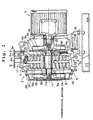
- Figs. 1 and 2 show a twin type oil-free scroll vacuum pump embodying the invention.
- the pump comprises a pump body 1 having a shaft 11, which is coupled at the right end to the drive shaft of a motor 2 and driven by the torque thereof.
- the shaft has an axially central eccentric portion 11a having a slightly greater diameter.
- the eccentric portion 11a is rotatable with its opposite end portions supported in bearings of housing halves 4 and 5 and packings.
- the housing halves 4 and 5 are disc-like and constitute respective stationary scrolls. Their peripheral walls are sealed to each other via an intervening seal member, thus defining a sealed space in them.
- the housing half 4 has a lap sliding surface 4b perpendicular to its axial direction.
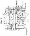
- a central hole 4i (Fig. 2) is formed, in which a non-eccentric portion of the shaft 11 other than the eccentric portion 11a is rotatably fitted.
- a spiral lap 7 is embedded with its end 7a (Fig. 3) in the vicinity of the hole 4i, for clockwise rotation when viewed in the direction of arrow 30.
- the lap 7 has a tip groove formed along its tip.
- a tip seal 14 (Fig. 2) is fitted, which is made of a fluorine resin or the like and has self-lubricating property so that it provides perfect seal with its associated lap sliding surface in contact therewith.
- the lap sliding surface 4b has a discharge port 4c (Figs. 2 and 3) with an opening thereof located in the vicinity of the end 7a of the lap 7. Compressed gas is discharged through a discharge port 4c and a discharge passage 4d and from discharge opening 9 formed in the outer peripheral surface 4a of the housing half 4 to the outside.
- the housing half 4 has a stem portion 4f on the side opposite the lap having a gas ballast gas inlet duct 10. Gas is introduced through the inlet duct 10 and a passage 4g and from an inlet port 4e into a sealed space R.
- Three revolving mechanisms 17 are provided in peripheral portions of the housing half 4 at circumferential interval of 120°.
- the revolving mechanisms 17 are coupled to a revolving scroll to be described later.
- the housing half 4 has a withdrawal opening 8 formed in its outer periphery.
- the withdrawal opening 8 is coupled to a vessel (not shown) to be evacuated. Gas in the vessel thus can be withdrawn through an opening 8a.
- the housing half 5 has a lap sliding surface 5b perpendicular to its axial direction.
- a central hole is formed, in which a non-eccentric portion of the shaft 11 other than the eccentric portion 11a is rotatably fitted.
- a spiral lap 6 is embedded with its end in the vicinity of and around the hole for counterclockwise rotation when viewed in the direction of arrow 31.
- the lap 6 has a tip groove formed along its tip.
- a tip seal 14 (Fig. 2) is fitted in the tip groove, which provides for perfect seal with the associated lap sliding surface in contact therewith.
- a revolving scroll 3 is disposed for revolving in the inner space defined by the housing halves 4 and 5.
- the revolving scroll 3 is disc-like and has laps 26 and 27 embedded in its opposite side lap sliding surfaces 3d and 3f and capable of engaging with the associated stationary scroll laps.
- the lap 27 which engages with the lap 7 is rotatable clockwise when viewed in the direction of arrow 30, and the lap 26 which engages with the lap 6 is rotatable counterclockwise when viewed in the direction of arrow 30.
- the revolving scroll 3 has a central hole 3a, in which the eccentric portion 11a of the shaft 11 is rotatably fitted.
- the hole 3a is surrounded by the laps 26a and 27a (Fig. 2) over the entire length of the eccentric portion 11a of the shaft 11.
- a sealed space R into which gas ballast gas is introduced is defined by the lap 7 of the stationary scroll and the lap 26 of the revolving scroll 3.
- Another sealed space L is defined by the lap 6 of the stationary scroll and the lap 26 of the revolving scroll 3.
- the sealed spaces R and L are communicated with each other by a communication passage 3e.
- gas introduced through the inlet duct 10 is led through the sealed space R and communication passage 3e to fill the sealed space L.
- fans 12 and 13 for cooling the vacuum pump 11 are provided on portions of the shaft 11 extending outward from the housing halves 5 and 4, and are protected by covers 18 and 19 having pluralities of air vent holes and mounted on the housing halves 5 and 4.
- three revolving mechanisms 17 are provided at a circumferential spacing of 120 r such that they are supported at one end in an outer peripheral portion of the revolving scroll and at the other end in the housing 4.
- the revolving scroll is revolved via the revolving mechanisms 17 about an axis of revolution which is eccentric with the stationary scrolls.
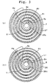
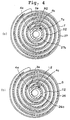
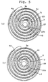
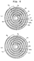
- Figs. 3(a) and 3(b) to 6(a) and 6(b) are views taken along line A-A in Fig. 2
- Figs. 3(b) to 6(b) are views taken along line B-B in Fig. 2.
- the revolving scroll 3 undergoes revolution to withdraw gas from a vessel (not shown).
- the gas is introduced from the outer periphery of the stationary scroll laps 6 and 7 by the revolving scroll laps 26 and 27 into sealed spaces defined by the laps of the stationary and revolving scrolls to be compressed in these sealed spaces.
- sealed space R0 as shown in Fig. 6(a)
- sealed space R1 as shown in Fig. 3(a
- the pressure in the sealed space R1 into which gas is introduced through the inlet port 4e is already higher than the external atmospheric pressure when the pressure in the vessel to be evacuated is close to the atmospheric pressure.
- gas to be introduced through the gas ballast gas inlet duct 10 is under a higher pressure than the pressure in the vessel, it is not introduced through the inlet port 4e.
- the sealed spaces R and L are changed in volume to R1 and L1 (Figs. 3(a) and 3(b)), R3 an L3 (Figs. 5(a) and 5(b)), then to R2 and L2 (Figs. 4(a) and 4(b), and then to R4 and L4 (Figs. 6(a) and 6(b), and the compressed gas is discharged through the discharge port 4c.
- the ratio of the water vapor contained in the introduced gas is reduced. Also, the fluid containing the water vapor is compressed down to the volumes R2 and L2 (Figs. 4(a) and 4(b)), and then to the volumes R3 and L3 (Figs. 5(a) and 5(b)).
- the pressure of the compression fluid in the sealed spaces becomes higher than the pressure of the gas ballast gas.
- compression fluid that flows reversely through the inlet port 4e is slight because the inlet port 4e is small in diameter, the revolving scroll is driven at a high speed and gas ballast gas is present in the inlet duct.
- the inlet port 4e of the stationary scroll is closed by the laps 26a and 27a of the revolving scrolls.
- the partial water vapor pressure when the sealed spaces are compressed and communicated with the discharge port (Figs. 6(a) and 6(b)), is reduced to be lower than the saturation vapor pressure in the pump.
- the compressed fluid is thus discharged through the discharge port 4c without liquefaction of the water vapor while gassifying water attached to the lap surfaces as a result of condensation and liquefaction of water vapor.
- the sealed spaces S0(a) and T0(b) as shown in Figs., 6(a) and 6(b) are compressed to volumes S1(a) and T1(b) as shown in Figs. 3(a) and 3(b).
- the gas ballast gas inlet port is not present in these compressed sealed spaces.
- the sealed spaces are communicated with their volumes S3 and T3 as shown in Figs. 5(a) and 5(b) with the discharge port 4c, whereby the compressed fluid is discharged to the outside.
- the saturation vapor pressure is exceeded, so that it is possible that water is generated as a result of condensation and liquefaction of water vapor and attached to and accumulated on the lap surfaces defining the final sealed spaces.
- the opening of the gas ballast gas inlet port 4e is provided in the lap sliding surface for the revolving scroll such that it can be opened and closed with revolving scroll lap driving and is closed in synchronism to the instant when the final sealed space defined by the stationary and revolving scrolls is communicated with the discharge passage leading to the outside. That is, when the final sealed space is in communication with the discharge passage, it is not in communication with the gas ballast gas inlet port 4e. Reverse flow of the compression fluid back to the inlet port 4e is thus prevented, while the compressed fluid is discharged through the discharge passage to the outside.
- the reverse flow of the compression fluid is prevented with a simple arrangement of merely setting the diameter of the inlet port opening to be smaller than the lap width and without need of providing any particular check valve at the inlet port 4e.
- the revolving scroll has the laps formed on its front and back surfaces, respectively, and 200 is supported for revolution by the first and second stationary scrolls each having the lap thereof engaged with each of its laps, one of the first and second stationary scrolls has the gas ballast gas inlet port 4e, the revolving scroll has the communication hole 3e for supplying gas to the sealed space defined between it and the other stationary scroll, and the first-mentioned one stationary scroll has the discharge port 4c, so that the compression fluid in the sealed space is compressed together with the introduced to discharge the resultant gas to the outside.
- the inlet port 4e 300 and discharge port 4c are thus disposed concentratedly on the portion of one stationary scroll on the side thereof opposite the lap. Simpler structure and readier manufacture are thus obtainable compared to the case where the individual ports are disposed distributedly in the two stationary scrolls.
- the gas introduced through the gas ballast gas inlet port 4e into the sealed space defined by one lap of the revolving scroll and the lap of one stationary scroll is introduced through the communication hole 3e formed in the revolving scroll into the other sealed space defined by the other lap of the revolving scroll and the lap of the other stationary scroll.
- the gas ballast gas inlet port thus need not be provided in both the stationary scrolls, but it may be provided in only one of the stationary scrolls. Simpler structure and readier manufacture thereof are thus obtainable.
- gas from the gas ballast gas inlet port is introduced into the sealed spaces R and L, this is by no means limitative; it is possible to introduce the gas ballast gas into the sealed spaces S and T.
- the gas ballast gas inlet duct 10 and discharge passages 4c and 4d, may be provided on the side of the housing half 5 instead of the side of the housing half 4.
- both the housing halves 4 and 5 with inlet ducts to introduce gas ballast gas into the sealed spaces R and L formed by the revolving and stationary scroll laps from both sides.
- the communication hole 3e communicating the sealed spaces R and L with each other is unnecessary.
- gas ballast gas is introduced quickly from both sides, the pumping efficiency can be increased.
- the external atmospheric air may be introduced through the inlet duct 10.
- air, N 2 gas or like dry gas may be introduced by heating it. Doing so accelerates the drying of water vapor or liquid in the sealed space defined by the scroll laps, thus promoting the prevention of deterioration.
- gas is introduced through the gas ballast gas inlet port provided in the stationary scroll into the sealed space defined by the stationary and revolving scroll laps engaged with one another for compression together with compression fluid in the sealed space. Liquid generated in the pump as a result of condensation, thus can be discharged to the outside.
Landscapes
- Engineering & Computer Science (AREA)
- Mechanical Engineering (AREA)
- General Engineering & Computer Science (AREA)
- Applications Or Details Of Rotary Compressors (AREA)
- Rotary Pumps (AREA)
Description
Claims (4)
- An oil-free scroll vacuum pump for compressing fluid with revolving (3) and stationary (4, 5) scrolls to discharge the compressed fluid to the outside, characterized in that:gas is introduced into a sealed space (L, R) defined by laps (6, 7, 26, 27) of the scrolls engaged with one another through a gas ballast inlet port (4e) formed in the stationary scroll (4); andthe introduced gas is compressed together with compression fluid in the sealed space, the resultant fluid being discharged to the outside.
- The oil-free scroll vacuum pump according to claim 1, wherein:three or more sealed spaces are formed in a prior stage to the gas introduction sealed space, in which fluid is compressed.
- The oil-free scroll vacuum pump according to claim 1, wherein:the gas ballast inlet port (4e) has an opening formed in a lap sliding surface (4b) for the revolving scroll the opening having a diameter smaller than the lap width and being capable of being opened and closed with the driving of the revolving scroll lap (26, 27); andthe opening of the gas ballast inlet port (4e) is closed in synchronism to an instant when the final sealed space (L4, R4) formed between the stationary (4, 5) and revolving (3) scrolls is communicated with a discharge passage (4c, 4d) leading to the outside.
- The oil-free scroll vacuum pump according to claim 1, wherein:the pump comprises a revolving scroll (3) having laps (26, 27) each formed on each of the front and back slides, the revolving scroll being capable of being driven for revolving with respect to a first and a second stationary scroll (4, 5) each having a lap (6, 7) engaged with each of the revolving scroll laps;the gas ballast inlet port (4e) being provided in either of the first and second stationary scrolls, the sealed space (L) formed by the other stationary scroll (5) and the revolving scroll (3) being communicated with a gas supply passage (3e, 4e) for supplying the gas; andthe afore-said one stationary scroll (4) having a discharge port (4c), through which resultant fluid resulting from the compression of compression fluid in the sealed space (L, R) together with the introduced gas is discharged to the outside.
Applications Claiming Priority (3)
| Application Number | Priority Date | Filing Date | Title |
|---|---|---|---|
| JP20760195 | 1995-07-21 | ||
| JP20760195A JP3388657B2 (en) | 1995-07-21 | 1995-07-21 | Oil-free scroll vacuum pump |
| JP207601/95 | 1995-07-21 |
Publications (3)
| Publication Number | Publication Date |
|---|---|
| EP0754860A2 EP0754860A2 (en) | 1997-01-22 |
| EP0754860A3 EP0754860A3 (en) | 1998-01-07 |
| EP0754860B1 true EP0754860B1 (en) | 2002-04-10 |
Family
ID=16542485
Family Applications (1)
| Application Number | Title | Priority Date | Filing Date |
|---|---|---|---|
| EP96111523A Expired - Lifetime EP0754860B1 (en) | 1995-07-21 | 1996-07-17 | Oil-free scroll vacuum pump |
Country Status (4)
| Country | Link |
|---|---|
| US (1) | US5743719A (en) |
| EP (1) | EP0754860B1 (en) |
| JP (1) | JP3388657B2 (en) |
| DE (1) | DE69620511T2 (en) |
Cited By (2)
| Publication number | Priority date | Publication date | Assignee | Title |
|---|---|---|---|---|
| EP3647599B1 (en) | 2019-10-07 | 2021-12-22 | Pfeiffer Vacuum Gmbh | Vacuum pump, scroll pump and method of manufacturing same |
| US11773849B2 (en) | 2019-10-07 | 2023-10-03 | Pfeiffer Vacuum Gmbh | Vacuum pump, scroll pump, and manufacturing method for such |
Families Citing this family (8)
| Publication number | Priority date | Publication date | Assignee | Title |
|---|---|---|---|---|
| JP3985051B2 (en) * | 1997-07-28 | 2007-10-03 | 独立行政法人 日本原子力研究開発機構 | Double wrap dry scroll vacuum pump |
| US6162033A (en) * | 1998-07-23 | 2000-12-19 | Carrier Corporation | Compressor economizer tube assembly |
| AU1101200A (en) * | 1998-10-05 | 2000-04-26 | Objectsoft, Corporation | An information access system |
| US6953330B1 (en) | 2004-08-02 | 2005-10-11 | Anest Iwata Corporation | Scroll vacuum pump |
| GB201007028D0 (en) * | 2010-04-28 | 2010-06-09 | Edwards Ltd | Scroll pump |
| CN102562588B (en) * | 2012-01-17 | 2015-02-25 | 杨广衍 | Oil-free vortex fluid mechanical device and method |
| US9341186B2 (en) | 2013-04-30 | 2016-05-17 | Agilent Technologies, Inc. | Scroll vacuum pump and method of maintenance including replacing a tip seal of a scroll vacuum pump |
| CN103437998B (en) * | 2013-07-10 | 2016-08-10 | 佛山市广顺电器有限公司 | A kind of oil-free vortex air compressor |
Family Cites Families (12)
| Publication number | Priority date | Publication date | Assignee | Title |
|---|---|---|---|---|
| US2885143A (en) * | 1955-07-29 | 1959-05-05 | W M Welch Mfg Company | Vacuum pump |
| GB1248031A (en) * | 1967-09-21 | 1971-09-29 | Edwards High Vacuum Int Ltd | Two-stage rotary vacuum pumps |
| FR2153129B2 (en) * | 1971-06-01 | 1974-01-04 | Vulliez Paul | |
| FR2487446B1 (en) * | 1980-07-23 | 1985-09-27 | Cit Alcatel | ELECTRIC PUMP GROUP WITH PALLET, OIL SEAL, REDUCED SIZE |
| IT1135031B (en) * | 1981-01-14 | 1986-08-20 | Generalvacuum Spa | IMPROVEMENTS IN OR RELATED TO CAPSULISM PUMPS |
| JPS631782A (en) * | 1986-06-20 | 1988-01-06 | Tokico Ltd | Scroll type vacuum pump |
| JPH03111690A (en) * | 1989-09-22 | 1991-05-13 | Tokuda Seisakusho Ltd | Vacuum pump |
| JPH0684753B2 (en) * | 1989-10-23 | 1994-10-26 | 株式会社日立製作所 | Scroll type vacuum pump |
| JP2618501B2 (en) * | 1989-10-30 | 1997-06-11 | 株式会社日立製作所 | Low-temperature scroll type refrigerator |
| US5258046A (en) * | 1991-02-13 | 1993-11-02 | Iwata Air Compressor Mfg. Co., Ltd. | Scroll-type fluid machinery with seals for the discharge port and wraps |
| JPH04117195U (en) * | 1991-04-02 | 1992-10-20 | サンデン株式会社 | scroll compressor |
| DE4325281A1 (en) * | 1993-07-28 | 1995-02-02 | Leybold Ag | Vacuum pump with a gas ballast device |
-
1995
- 1995-07-21 JP JP20760195A patent/JP3388657B2/en not_active Expired - Lifetime
-
1996
- 1996-07-17 US US08/682,256 patent/US5743719A/en not_active Expired - Lifetime
- 1996-07-17 DE DE69620511T patent/DE69620511T2/en not_active Expired - Lifetime
- 1996-07-17 EP EP96111523A patent/EP0754860B1/en not_active Expired - Lifetime
Cited By (2)
| Publication number | Priority date | Publication date | Assignee | Title |
|---|---|---|---|---|
| EP3647599B1 (en) | 2019-10-07 | 2021-12-22 | Pfeiffer Vacuum Gmbh | Vacuum pump, scroll pump and method of manufacturing same |
| US11773849B2 (en) | 2019-10-07 | 2023-10-03 | Pfeiffer Vacuum Gmbh | Vacuum pump, scroll pump, and manufacturing method for such |
Also Published As
| Publication number | Publication date |
|---|---|
| EP0754860A3 (en) | 1998-01-07 |
| JP3388657B2 (en) | 2003-03-24 |
| EP0754860A2 (en) | 1997-01-22 |
| US5743719A (en) | 1998-04-28 |
| DE69620511D1 (en) | 2002-05-16 |
| JPH0932767A (en) | 1997-02-04 |
| DE69620511T2 (en) | 2002-11-28 |
Similar Documents
| Publication | Publication Date | Title |
|---|---|---|
| US5743719A (en) | Oil-free scroll vacuum pump having a gas ballast part | |
| KR890000130B1 (en) | Scroll fluid apparatus handling compressible fluid | |
| JPH079239B2 (en) | Screw vacuum pump | |
| US7086844B2 (en) | Multi-stage scroll fluid machine having a set a seal elements between compression sections | |
| EP0863313A1 (en) | Two stage scroll compressor | |
| JP2006083844A (en) | Multi-cylinder rotary compressor | |
| EP0798463A2 (en) | Oil-free scroll vacuum pump | |
| JP2005307978A (en) | Multi-stage vacuum pump and pump equipment with that kind of pump | |
| KR930010816B1 (en) | Helical vane type compressor compensates for thrust loss | |
| JPS61152990A (en) | Screw vacuum pump | |
| KR0132990Y1 (en) | Compressor of Rotary Compressor | |
| KR102663577B1 (en) | Electro-compressor | |
| KR100408246B1 (en) | Gas discharge structure of rotary twin compressor | |
| WO2022224727A1 (en) | Screw compressor | |
| JP2002174174A (en) | Vacuum exhaust device | |
| KR100296246B1 (en) | Cylinder assembly of hermetic rotary compressor | |
| KR0140048B1 (en) | Rotary compressor | |
| KR100679885B1 (en) | Compressor of Swivel Vane Compressor with Lateral Suction Structure | |
| KR100259811B1 (en) | Device for preventing axial flow leak of scroll compressor | |
| JP4080805B2 (en) | Scroll fluid machinery | |
| JP3884101B2 (en) | Oil-free scroll vacuum pump | |
| JP2706105B2 (en) | Vane compressor | |
| JPH04262085A (en) | Scroll compressor | |
| JPH1026092A (en) | Compressor | |
| KR20010035864A (en) | Structure for reducing gas-leakage of scrollcompressor |
Legal Events
| Date | Code | Title | Description |
|---|---|---|---|
| PUAI | Public reference made under article 153(3) epc to a published international application that has entered the european phase |
Free format text: ORIGINAL CODE: 0009012 |
|
| AK | Designated contracting states |
Kind code of ref document: A2 Designated state(s): DE FR GB IT |
|
| PUAL | Search report despatched |
Free format text: ORIGINAL CODE: 0009013 |
|
| AK | Designated contracting states |
Kind code of ref document: A3 Designated state(s): DE FR GB IT |
|
| RAP1 | Party data changed (applicant data changed or rights of an application transferred) |
Owner name: ANEST IWATA CORPORATION |
|
| 17P | Request for examination filed |
Effective date: 19980626 |
|
| GRAG | Despatch of communication of intention to grant |
Free format text: ORIGINAL CODE: EPIDOS AGRA |
|
| 17Q | First examination report despatched |
Effective date: 20010305 |
|
| GRAG | Despatch of communication of intention to grant |
Free format text: ORIGINAL CODE: EPIDOS AGRA |
|
| GRAG | Despatch of communication of intention to grant |
Free format text: ORIGINAL CODE: EPIDOS AGRA |
|
| GRAH | Despatch of communication of intention to grant a patent |
Free format text: ORIGINAL CODE: EPIDOS IGRA |
|
| GRAH | Despatch of communication of intention to grant a patent |
Free format text: ORIGINAL CODE: EPIDOS IGRA |
|
| REG | Reference to a national code |
Ref country code: GB Ref legal event code: IF02 |
|
| GRAH | Despatch of communication of intention to grant a patent |
Free format text: ORIGINAL CODE: EPIDOS IGRA |
|
| GRAA | (expected) grant |
Free format text: ORIGINAL CODE: 0009210 |
|
| AK | Designated contracting states |
Kind code of ref document: B1 Designated state(s): DE FR GB IT |
|
| REF | Corresponds to: |
Ref document number: 69620511 Country of ref document: DE Date of ref document: 20020516 |
|
| ET | Fr: translation filed | ||
| PLBE | No opposition filed within time limit |
Free format text: ORIGINAL CODE: 0009261 |
|
| STAA | Information on the status of an ep patent application or granted ep patent |
Free format text: STATUS: NO OPPOSITION FILED WITHIN TIME LIMIT |
|
| 26N | No opposition filed |
Effective date: 20030113 |
|
| PGFP | Annual fee paid to national office [announced via postgrant information from national office to epo] |
Ref country code: FR Payment date: 20080604 Year of fee payment: 13 |
|
| REG | Reference to a national code |
Ref country code: FR Ref legal event code: ST Effective date: 20100331 |
|
| PG25 | Lapsed in a contracting state [announced via postgrant information from national office to epo] |
Ref country code: FR Free format text: LAPSE BECAUSE OF NON-PAYMENT OF DUE FEES Effective date: 20090731 |
|
| PGFP | Annual fee paid to national office [announced via postgrant information from national office to epo] |
Ref country code: DE Payment date: 20150721 Year of fee payment: 20 Ref country code: GB Payment date: 20150721 Year of fee payment: 20 |
|
| PGFP | Annual fee paid to national office [announced via postgrant information from national office to epo] |
Ref country code: IT Payment date: 20150727 Year of fee payment: 20 |
|
| REG | Reference to a national code |
Ref country code: DE Ref legal event code: R071 Ref document number: 69620511 Country of ref document: DE |
|
| REG | Reference to a national code |
Ref country code: GB Ref legal event code: PE20 Expiry date: 20160716 |
|
| PG25 | Lapsed in a contracting state [announced via postgrant information from national office to epo] |
Ref country code: GB Free format text: LAPSE BECAUSE OF EXPIRATION OF PROTECTION Effective date: 20160716 |