EP0754792A1 - Method of knitting single knit fabric - Google Patents
Method of knitting single knit fabric Download PDFInfo
- Publication number
- EP0754792A1 EP0754792A1 EP96110312A EP96110312A EP0754792A1 EP 0754792 A1 EP0754792 A1 EP 0754792A1 EP 96110312 A EP96110312 A EP 96110312A EP 96110312 A EP96110312 A EP 96110312A EP 0754792 A1 EP0754792 A1 EP 0754792A1
- Authority
- EP
- European Patent Office
- Prior art keywords
- yarn
- needles
- knitting
- needle
- section
- Prior art date
- Legal status (The legal status is an assumption and is not a legal conclusion. Google has not performed a legal analysis and makes no representation as to the accuracy of the status listed.)
- Granted
Links
Images


Classifications
-
- D—TEXTILES; PAPER
- D04—BRAIDING; LACE-MAKING; KNITTING; TRIMMINGS; NON-WOVEN FABRICS
- D04B—KNITTING
- D04B15/00—Details of, or auxiliary devices incorporated in, weft knitting machines, restricted to machines of this kind
- D04B15/66—Devices for determining or controlling patterns ; Program-control arrangements
-
- D—TEXTILES; PAPER
- D04—BRAIDING; LACE-MAKING; KNITTING; TRIMMINGS; NON-WOVEN FABRICS
- D04B—KNITTING
- D04B1/00—Weft knitting processes for the production of fabrics or articles not dependent on the use of particular machines; Fabrics or articles defined by such processes
- D04B1/10—Patterned fabrics or articles
- D04B1/12—Patterned fabrics or articles characterised by thread material
- D04B1/126—Patterned fabrics or articles characterised by thread material with colour pattern, e.g. intarsia fabrics
-
- D—TEXTILES; PAPER
- D04—BRAIDING; LACE-MAKING; KNITTING; TRIMMINGS; NON-WOVEN FABRICS
- D04B—KNITTING
- D04B7/00—Flat-bed knitting machines with independently-movable needles
- D04B7/24—Flat-bed knitting machines with independently-movable needles for producing patterned fabrics
- D04B7/26—Flat-bed knitting machines with independently-movable needles for producing patterned fabrics with colour patterns
Definitions
- This invention relates to a method of knitting a single knit fabric on which a transit yarn portion appears such as an intarsia knit fabric.
- a multicolor single knit fabric such as an intarsia knit fabric
- two kinds of sections are present in the same course.
- One section is a knitting section in which a particular yarn is knitted.
- Another section is a non-knitting section in which not the particular yarn but another yarn is knitted. If the non-knitting section is present between a start point of the particular yarn and the knitting section, then the particular yarn supplied forms a transit yarn portion, i.e., crossover yarn portion, in the non-knitting section.
- a method of knitting a single knit fabric in which a yarn from a yarn feeder is not knitted but forms a transit yarn portion comprises the steps of successively advancing a plurality of needles corresponding to a non-knitting section within which the yarn forms the transit yarn portion beginning with a needle on the side of a start point of the transit yarn portion to lower the yarn from the yarn feeder below the needles, and engaging the yarn from the yarn feeder by another needle on the side of the yarn feeder than the advanced needles.
- the yarn from the yarn feeder having moved to the knitting section past the non-knitting section can be caught with certainty by the needles in the knitting section. Also, since the transit yarn portion is not knitted in the ground knit portion, it can be removed only by cutting the transit yarn portion and the operation is simple. Further, the quality is not be deteriorated, different from the prior art.
- the needles which are successively advanced may be selected from needles on one or both of a needle bed which takes part in knitting and another needle bed which does not take part in knitting.
- the needles which are successively advanced may be selected to all of those needles corresponding to the non-knitting section or every plurality of ones of those needles or else a plurality of ones of those needles farther by a plurality of knitting needles than the start point of the transit yarn portion.
- the another needle may be selected from one of the first needle of a knitting section in which the yarn from the yarn feeder is knitted and the last needle in the non-knitting section which is a needle on a needle bed which does not take part in knitting.
- the knitting machine to be used to perform the present invention is preferably, for example, a so-called carriageless flat-knitting machine which does not include a carriage for cams for moving a plurality of needles back and forth.
- a carriageless flat-knitting machine individually moves a plurality of needles back and forth by means of actuators such as linear motors.
- actuators such as linear motors.
- a plurality of needles are individually moved back and forth in synchronism with a movement of a yarn carrier, i.e., yarn feeder.
- a yarn carrier i.e., yarn feeder.
- a carriageless flat-knitting machine 10 includes two needle beds 12 and 14 disposed in an inverted V-shaped configuration in order to knit a multi-color single knit fabric, a plurality of needles 16 and 18 arranged in parallel to each other on the needle beds 12 and 14, respectively, and a plurality of yarn feeders, i.e., yarn carriers 20 each having one or more yarn guide holes.
- the needles 16 on the front side and the needles 18 on the rear side intersect with each other at front end portions thereof when they are advanced.
- Each of the needles 16 and 18 is moved back and forth in a predetermined pattern based on a predetermined knitting plan in synchronism with a movement of a yarn feeder 20 by an actuator or preferably a linear motor.
- the pattern of the back and forth movement of each needle can be represented in a chart wherein the axis of ordinate is represented by the amount of movement of the needle with respect to the position of zero given by the position of the knocking-over edge and the axis of abscissa is represented by the amount of movement of the yarn feeder or the time.
- Such a pattern is called wave pattern, knit pattern, needle movement pattern and so forth.
- Knitting yarns 22 of different types are threaded through the individual yarn feeders 20.
- Each of the yarn feeders 20 is reciprocated transversely above intersecting locations of the needles 16 and 18 by a yarn supply unit 30 so that it supplies the knitting yarn from above to the intersecting portions of the needles 16 and 18.
- the movement of each of the yarn feeders 20 is set based on the predetermined knitting plan.
- the yarn supply units 30 are supported for reciprocating motion in a longitudinal direction of and on a common rail 32 assembled to a frame of the knitting machine such that it extends transversely with respect to the frame.
- a driving mechanism for individually moving each of the yarn supply units 30 includes a pair of pulleys 34 mounted for rotation at locations of the rail 32 spaced away from each other in the longitudinal direction of the rail, and an endless belt 36 extending between the two pulleys.
- Each of the yarn supply units 30 includes a traveling member 40 supported for back and forth movement in the longitudinal direction of and on the rail 32 by a plurality of rollers 38, a stay 42 extending from the traveling member 40, and a connection member 44 for connecting the traveling member 40 to the endless belt 36.
- the rail 32 has a pair of guide grooves for partially receiving the rollers 38.
- Each of the yarn feeders 20 is attached to an end portion of the stay 42 of the corresponding yarn supply unit 30.
- Each of the yarn supply units 30 is reciprocated transversely based on the predetermined knitting plan as the corresponding endless belt 36 is circulated reciprocally by forward and backward rotations of a corresponding source of rotation not shown.
- While loops at an extreme end of a knit fabric 24 are, in the example shown in FIG. 1 wherein the needles 16 on the front side principally directly contribute to knitting, confined by the needles 16 on the front side, they may otherwise be confined by the needles 18 on the rear side which do not directly contribute to knitting.
- the actuators for driving needles and a control unit for controlling driving sources for the yarn supply units will be hereinafter described in detail with reference to FIG. 14.
- a knitting section is a section in which a yarn 22 from a yarn feeder 20 is used to knit whereas a non-knitting section is another section in which the yarn 22 is not used to knit but another yarn of another yarn feeder is used to knit.
- the yarn 22 from the yarn feeder 20 is not knitted in the non-knitting section but forms a transit yarn portion which extends across the non-knitting section.
- the route, that is, the height H, of the yarn 22 with respect to the needles 16 or 18 gradually becomes high like H1, H2, H3 and H4 from the side of the start point 26 of the yarn 22 toward the side of the yarn 22 until it becomes, at a terminal end portion of the non-knitting section, so high that the yarn 22 is not likely caught by the advanced needles 16 or 18.
- the start point of the yarn 22 is either a boundary between the non-knitting section and a knitting section preceding the non-knitting section as shown in (A) of FIG. 2 or an end portion of the knit fabric in its widthwise direction as shown in (B) of FIG. 2.
- the yarn is brought into contact, when one of the needles is advanced, with a front end of the needle and is guided, as the needle is further advanced, while being in contact with an arcuate portion of the front end of the needle, to the lower face of the needle. Consequently, the height of the yarn 22 extending from the start point 26 to the yarn feeder 20 is lowered to H4 at the location of the needle, and is restricted low to a substantially equal height also by another needle advanced next. As a result, the transit yarn portion is caught with certainty by the needles in the knitting section.
- Needles on a needle bed which takes part in knitting or needles on the other needle bed which does not take part in knitting may be successively advanced as shown in (A) of FIG. 4, or needles on both of the needle beds may be successively advanced respectively as shown in (B) of FIG. 4.
- needles on the needle bed which takes part in knitting are advanced, preferably the needles are not advanced farther than the tuck position so that loops caught by the needles may not turn over or fall and be cleared from the latches.
- needles on the needle bed which does not take part in knitting are advanced, since they are empty needles, they may be advanced to the clearing position.
- the amounts of advancement of the needles are set in such a manner as described just above depending upon whether or not they are needles on the needle bed which takes part in knitting.
- Those needles which are successively advanced to push down or hold down the transit yarn portion may be all needles corresponding to the non-knitting section or every plurality of those needles, or else, a plurality of needles following a plural numbered one of those needles following the start point of the transit yarn portion may be successively advanced.
- all of the needles following the plural numbered needle may be successively advanced or every plurality of ones of those needles may be successively advanced.
- Those needles which have been successively advanced to push down or hold down the transit yarn portion may be retracted at an arbitrary timing after the transit yarn portion is engaged with a needle nearer to the yarn feeder than the successively advanced needles such as the last needle in the non-knitting section or the first needle in the following knitting section, or they may be successively retracted in the same order as in the advancement.
- the needle advanced last preferably, a plurality of needles advanced last, from among the successively advanced needles are not retracted until after the transit yarn portion is engaged with a predetermined needle.
- the needle for engaging the yarn 22 may be either one of the first needle in the knitting section in which the yarn from the yarn feeder is knitted (a needle on the most upstream in the traveling direction of the yarn feeder from among the needles in the knitting section, or in other words, a needle nearest to the non-knitting section) and the last needle in the non-knitting section from among the needles of the needle bed which does not take part in knitting (a needle on the most downstream in the traveling direction of the yarn feeder from among the needles in the non-knitting section, or in other words, a needle nearest to the knitting section).
- the yarn is preferably engaged by the last needle in the non-knitting section as described above, the yarn may alternatively be engaged, alternatively of the last needle, by any needle positioned at an end portion of the non-knitting section adjacent the knitting section (except the last needle).
- the needle for engaging the yarn 22 is the first needle in the knitting section, the catching of the yarn by the needle is followed by knitting in the knitting section.
- the needle for engaging the yarn 22 is the last needle in the non-knitting section, the yarn 22 is removed from the last needle in the non-knitting section at an arbitrary timing after knitting of the knitting section is started.
- the amount of advancement of a needle for pushing down a yarn is determined such that the needles 16 on the front side which contribute to knitting are advanced to the tuck position whereas the needles 18 on the rear side which do not contribute to knitting are advanced farther than the tuck position, for example, to the clearing position. Further, it is assumed that the distance between a needle in the non-knitting section which first starts advancement in order to push down a yarn and the yarn feeder 20a then is set sufficiently greater than the distance between an advancement of the needle upon ordinary knitting and the position of the yarn feeder then.
- the needles 16 on the front side are used as needles which directly take part in knitting whereas the needles 18 on the rear side are used as needles which indirectly take part in knitting but do not directly take part in knitting.
- the needle bed 12 to which the needles 16 on the front side belong is merely referred to as needle bed which takes part in knitting whereas the needle bed 14 to which the needles 18 on the rear side belong is referred to as needle bed which does not take part in knitting.
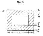
- FIGS. 5, 6 and 7 show an embodiment wherein an intarsia knit fabric is knitted by a carriageless flat-knitting machine provided with three yarn feeders 20a, 20b and 20c.
- the first embodiment in a course which includes a non-knitting section, all needles in the non-knitting section are advanced to hold down a transit yarn portion, and then the needles are successively retracted in the same order as in the advancement so that the transit yarn portion is finally caught and confined by the first needle in a next knitting section.
- courses A1 to An and C1 to Cn are knitted with a black yarn 22a from the yarn feeder 20a in the entire sections Wa, Wb and Wc.
- Courses B1 to Bm are, in the section Wa, knitted with the yarn 22a from the yarn feeder 20a, in the section Wb, knitted with a white yarn 22b from the yarn feeder 20b, and in the section Wc, knitted with a black yarn 22c from the yarn feeder 20c.
- FIGS. 6 and 7 show the yarn 22a from the yarn feeder 20a in order to facilitate understanding.
- the courses A1 to An are knitted by the following process.
- the yarn feeder 20a, 20b and 20c stand by at predetermined standby positions, for example, at leftward positions in FIGS. 6 and 7.
- the yarn feeder 20a is fed, that is, moved from the left to the right in FIGS. 6 and 7 (depending upon a course, in the opposite direction), and predetermined ones of the needles 16 on the front side corresponding to the sections Wa, Wb and Wc are moved, that is, driven, during the movement of the yarn feeder 20a. Consequently, the courses A1 to An are knitted, in the entire sections Wa, Wb and Wc, with the yarn 22a.
- the direction of movement of the yarn feeder 20a is reversed for each course such that the yarn feeder 20a is moved from the left to the right in the course A1, but from the right to the left in the next course A2.
- the yarn feeder 20a is returned to the predetermined standby position, for example, to the leftward position in FIGS. 6 and 7.
- the courses B1 to Bm are respectively knitted by the following process. It is to be noted that it is assumed that, when knitting of the course An is completed, the yarn feeders 20a, 20b and 20c stand by at the predetermined positions, for example, at the positions leftward of the knit fabric as shown in (A) of FIG. 6 in which the yarn feeder 20a is shown as a representative.
- the courses C1 to Cn are knitted by the following process.
- the yarn feeders 20a, 20b and 20c are positioned leftwardly (or rightwardly) of the sections Wa, Wb and Wc, respectively.
- the yarn feeders 20a, 20b and 20c are first moved to the right side of the knit fabric and thereafter made to stand by at the positions.
- the yarn feeder 20a is moved from the right to the left in FIG. 6 (depending upon a course, in the opposite direction), and the predetermined needles 16 corresponding to the sections Wa, Wb and Wc are moved during the movement of the yarn feeder 20a. Consequently, the courses C1 to Cn are knitted in the entire sections Wa, Wb and Wc with the yarn 22a.
- the present invention can be performed also with a flat-knitting machine other than a carriageless type flat-knitting machine, for example, with a carriage type flat-knitting machine in which needles are moved by a cam.
- a method of knitting a knit fabric of the knit pattern shown in FIG. 5 on a carriage type flat-knitting machine will be described.
- the courses A1 to An and C1 to Cn are knitted with the yarn 22a from the yarn feeder 20a in the entire sections Wa, Wb and Wc, and the courses B1 to Bm are knitted with the yarns 22a, 22b and 22c from the yarn feeders 20a, 20b and 20c in the sections Wa, Wb and Wc, respectively.
- each of the courses A1 to An similarly as in the first embodiment, the carriage is moved together with the yarn feeder 20a from the right to the left or reversely while the yarn feeders 20b and 20c stand by at predetermined standby positions on the left side of the knit fabric.
- the courses A1 to An are knitted in the sections Wa, Wb and Wc with the yarn 22a.
- the carriage and the yarn feeder 20a are returned to the predetermined standby position on the left side of the knit fabric.
- the course B1 is knitted by the following process.
- FIG. 8 shows an embodiment wherein the three-color intarsia knit fabric shown in FIG. 5, particularly the courses B1 to Bn are knitted by a carriageless type flat-knitting machine provided with three yarn feeders 20a, 20b and 20c.
- a transit yarn portion is caught by the last one of needles corresponding to the non-knitting section from among needles on a needle bed which does not directly take part in knitting, that is, a needle nearest to a next knitting section. After the transit yarn portion is caught and confined by the needle, the needles advanced so as to hold down the transit yarn portion are retracted.
- FIGS. 9 and 10 show an embodiment wherein the three-color intarsia knit fabric shown in FIG. 5, particularly, the courses B1 to Bn are knitted by a carriageless type flat knitting machine provided with three yarn feeders 20a, 20b and 20c.
- the transit direction and the knitting direction in the first course are opposite to each other and the left and right positions at which a transit yarn is caught are reverse to those in the third embodiment.
- a rib structure is present at one end or both ends of a knit fabric in its widthwise direction
- a yarn 22 from a yarn feeder 20 is connected to an end of a knit fabric 24 as shown in FIG. 12
- the yarn 22 from the yarn feeder 20 is caught by a loop Q50 in the rib knit portion and the route of the yarn 22 becomes so high as indicated by an alternate long and short dashes line that often the yarn 22 cannot be caught by needles used to knit.
- the yarn 22 from the yarn feeder 20 is held down by the loop Q50 in the rib knit portion as indicated by an alternate long and two short dashes line in FIG. 11 and the route of the yarn 22 is lowered.
- FIG. 13 illustrates an embodiment of a knitting method wherein, in order to end knitting of an intarsia knit fabric based only on a plain stitch on a carriageless type flat-knitting machine provided with three yarn feeders 20a, 20b and 20c, transit yarn processing is performed when a yarn feeder goes out of the knit fabric.
- the left end and the right end of the knit fabric are denoted by reference numerals 241 and 242, respectively.
- the present invention can be performed also by a carriage type flat-knitting machine by moving the yarn feeders and the needles by means of a carriage.
- the present invention can be applied also to a knit fabric whose knitting width gradually increases as shown in FIG. 15.
- a yarn from a yarn feeder is not knitted in a range from a portion thereof gripped by a gripping member to a knitting section. Consequently, the yarn from the yarn feeder forms a transit yarn portion in the range.
- the yarn 22 from the yarn feeder 20 should be engaged with, for example, the first needle in the knitting section after a plurality of needles corresponding to the non-knitting section are successively advanced beginning with the needle nearest to an end portion (start point 26) of the transit yarn portion. Thereafter, the needles in the non-knitting section advanced formerly are retracted.
- FIG. 14 shows an embodiment of a control unit 60 used for a carriageless type flat-knitting machine on which the knitting method described above is performed.
- the carriageless type flat-knitting machine includes a plurality of actuators 62 1 to 62n provided corresponding to needles for individually moving the corresponding needles back and fourth, and a plurality of driving sources 64 1 to 64m provided corresponding to yarn feeders for individually and transversely reciprocating the corresponding yarn feeders.
- a DC linear motor is employed for the actuators.
- An electric motor with a speed reducer is used for the driving sources.
- the control unit 60 includes a plurality of first controllers 66 1 to 66n individually provided corresponding to the actuators for controlling the movements and the positions of the corresponding actuators, and a plurality of second controllers 68 1 to 68m individually provided corresponding to the driving sources for controlling the rotations and positions of the corresponding driving sources.
- the first and second controllers 66 1 to 66n and 68 1 to 68m are individually provided by numbers equal to the numbers of the corresponding actuators and yarn feeders, respectively.
- the first controllers 66 1 to 66n include memories 70 1 to 70n for storing operations of the first controllers based on a predetermined knitting plan, respectively.
- the second controllers 68 1 to 68m include memories 72 1 to 72m for storing operations of the second controllers based on the predetermined knitting plan.
- the first and second controllers 66 1 to 66n and 68 1 to 68m are connected to a common main controller 74 for providing timing signals of operations to the first controllers.
- the first controllers control the positions of the needles in synchronism with the operations of the second controllers.
- the second controllers control the positions of the yarn feeders.
- the main controller 74 is connected to the memory 76 in which operations of the main controller 74 based on the predetermined knitting plan are stored.
- Data to be stored into the memories 70 1 to 70n and 72 1 to 72m are data based on the predetermined knitting plan and are produced by a knitting design computer 78 based on the predetermined knitting plan.
- the data produced by the knitting design computer 78 are either supplied directly to the individual memories by communication means such as a data communication line or supplied indirectly into the individual memories via some other communication means such as a tape, a disk or a bubble memory.
- the data stored in the memories of the first controllers 66 1 to 66n are position data of the corresponding actuators and hence the corresponding needles, knit pattern data and some other necessary data for individual knitting courses.
- the data stored in the memories of the second controllers 68 1 to 68m are data of the corresponding yarn supply units and hence the widths and moving speeds of reciprocating motions of the yarn feeders and so forth for individual knitting courses and some other necessary data.
- the data stored in the memory 76 of the main controller 74 are data in accordance with which selection of a yarn supply unit to be fed and selection of needles to be operated depending upon the positions of the yarn supply units are performed for each knitting course and some other necessary data.
- the first and second controllers 66 1 to 66n and 68 1 to 68m operate the corresponding actuators and driving sources based on the data in the corresponding memories under the control of the main controller 74. Consequently, the flat-knitting machine knits a multicolor single knit fabric having a predetermined knit pattern changing the feeding order of the plurality of yarn feeders in such a manner as described above.
Landscapes
- Engineering & Computer Science (AREA)
- Textile Engineering (AREA)
- Knitting Machines (AREA)
- Knitting Of Fabric (AREA)
Abstract
Description
- This invention relates to a method of knitting a single knit fabric on which a transit yarn portion appears such as an intarsia knit fabric.
- In a multicolor single knit fabric such as an intarsia knit fabric, two kinds of sections are present in the same course. One section is a knitting section in which a particular yarn is knitted. Another section is a non-knitting section in which not the particular yarn but another yarn is knitted. If the non-knitting section is present between a start point of the particular yarn and the knitting section, then the particular yarn supplied forms a transit yarn portion, i.e., crossover yarn portion, in the non-knitting section.
- In knitting of such a multicolor single knit fabric as described above, if a yarn carrier, i.e., yarn feeder, for a transit yarn is fed to a knitting section past a non-knitting section, then the route, that is, the height, of the transit yarn portion with respect to the needles corresponding to the knitting section becomes so high that it sometimes occurs that the yarn from the yarn feeder is not caught and not knitted by the needles corresponding to the knitting section. This is because the route of the yarn portion extending to the yarn feeder from a start point at an end portion (refer to (B) of FIG. 2) of the knit fabric in its widthwise direction or at a boundary (refer to (A) of FIG. 2) between the non-knitting section (that is, the transit yarn portion) and a knitting section preceding the non-knitting section gradually becomes high from the start point side toward the yarn feeder side until it becomes so high that the yarn is not caught readily by an advanced needle at a front end portion of another knitting section (at the end on the upstream side in the moving direction of the yarn feeder).
- As one of methods of catching a transit yarn portion with certainty by a needle corresponding to a knitting section, there is a method of catching an intermediate portion of a transit yarn portion at one or more locations by several needles corresponding to a non-knitting section so that the transit yarn portion is knitted in a ground knit portion knitted together with another yarn to knit a so-called tuck stitch to fix the intermediate portion of the transit yarn portion at the one or more locations to the knit fabric thereby to lower the route of the yarn. With such a method as described above, however, after the ground knit portion including transit yarn portions is delivered from a take-up apparatus, or after knitting of the knit fabric is completed, the transit yarn portions knitted in tuck stitches must be cut and removed from the ground knit portion, and this operation is cumbersome. Further, there is another problem that the color of the transit yarn portion knitted in the ground knit portion remains in the ground design, which deteriorates the quality.
- It is an object of the present invention to allow a transit yarn portion to be caught with certainty by needles in a knitting section next to a non-knitting section without complicating the operation or without deteriorating the quality.
- A method of knitting a single knit fabric in which a yarn from a yarn feeder is not knitted but forms a transit yarn portion according to the present invention comprises the steps of successively advancing a plurality of needles corresponding to a non-knitting section within which the yarn forms the transit yarn portion beginning with a needle on the side of a start point of the transit yarn portion to lower the yarn from the yarn feeder below the needles, and engaging the yarn from the yarn feeder by another needle on the side of the yarn feeder than the advanced needles.
- When a plurality of needles corresponding to a non-knitting section are successively advanced beginning with a needle nearest to a start point of the crossover yarn segment, the transit yarn portion is engaged with an arcuate face at a front end of one of the advanced needles so that it is guided to the lower face of the needle. Consequently, the route of the transit yarn portion extending from the start point toward the yarn feeder is lowered at the location of the needle, and it is held as low as the position also by another needle advanced next. As a result, the transit yarn portion is caught with certainty by needles in a knitting section.
- As described above, according to the present invention, the yarn from the yarn feeder having moved to the knitting section past the non-knitting section can be caught with certainty by the needles in the knitting section. Also, since the transit yarn portion is not knitted in the ground knit portion, it can be removed only by cutting the transit yarn portion and the operation is simple. Further, the quality is not be deteriorated, different from the prior art.
- The needles which are successively advanced may be selected from needles on one or both of a needle bed which takes part in knitting and another needle bed which does not take part in knitting. The needles which are successively advanced may be selected to all of those needles corresponding to the non-knitting section or every plurality of ones of those needles or else a plurality of ones of those needles farther by a plurality of knitting needles than the start point of the transit yarn portion. The another needle may be selected from one of the first needle of a knitting section in which the yarn from the yarn feeder is knitted and the last needle in the non-knitting section which is a needle on a needle bed which does not take part in knitting.
-
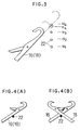
- FIG. 1 is a schematic side elevational view showing needles, yarn feeders and yarn supply units of a flat-knitting machine;
- FIG. 2 is a view for explaining a transit yarn;
- FIG. 3 is a view illustrating a relationship of the height of a transit yarn with respect to a needle;
- FIG. 4 is a view showing a state wherein a transit yarn is held down by a needle or needles;
- FIG. 5 is an explanatory view of a method of knitting an intarsia knit fabric;
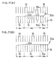
- FIG. 6 is a view illustrating steps of a first embodiment of the present invention;
- FIG. 7 is a view illustrating steps of the first embodiment following the steps of FIG. 6;
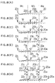
- FIG. 8 is a view showing steps for explaining a third embodiment of the present invention;
- FIG. 9 is a view illustrating steps of a fourth embodiment of the present invention;
- FIG. 10 is a view illustrating steps of the fourth embodiment following the steps of FIG. 9;
- FIG. 11 is a view illustrating steps of a fifth embodiment of the present invention;
- FIG. 12 is a view illustrating a relationship between loops and a yarn in the fifth embodiment;
- FIG. 13 is a view illustrating steps of a sixth embodiment of the present invention;
- FIG. 14 is a block diagram of an electric circuit showing an embodiment of a control unit; and
- FIG. 15 is a view illustrating a method of knitting another single knit fabric in accordance with the present invention.
- The knitting machine to be used to perform the present invention is preferably, for example, a so-called carriageless flat-knitting machine which does not include a carriage for cams for moving a plurality of needles back and forth. A carriageless flat-knitting machine individually moves a plurality of needles back and forth by means of actuators such as linear motors. In ordinary knitting, a plurality of needles are individually moved back and forth in synchronism with a movement of a yarn carrier, i.e., yarn feeder. One of such carriageless flat knitting machines is disclosed in the official gazette of Japanese Patent Application Publication No. Hei 1-12855.
- Referring to FIGS. 1 and 2, a carriageless flat-
knitting machine 10 includes twoneedle beds needles needle beds yarn carriers 20 each having one or more yarn guide holes. - The
needles 16 on the front side and theneedles 18 on the rear side intersect with each other at front end portions thereof when they are advanced. Each of theneedles yarn feeder 20 by an actuator or preferably a linear motor. The pattern of the back and forth movement of each needle can be represented in a chart wherein the axis of ordinate is represented by the amount of movement of the needle with respect to the position of zero given by the position of the knocking-over edge and the axis of abscissa is represented by the amount of movement of the yarn feeder or the time. Such a pattern is called wave pattern, knit pattern, needle movement pattern and so forth. - Knitting
yarns 22 of different types are threaded through theindividual yarn feeders 20. Each of theyarn feeders 20 is reciprocated transversely above intersecting locations of theneedles yarn supply unit 30 so that it supplies the knitting yarn from above to the intersecting portions of theneedles yarn feeders 20 is set based on the predetermined knitting plan. - The
yarn supply units 30 are supported for reciprocating motion in a longitudinal direction of and on acommon rail 32 assembled to a frame of the knitting machine such that it extends transversely with respect to the frame. A driving mechanism for individually moving each of theyarn supply units 30 includes a pair ofpulleys 34 mounted for rotation at locations of therail 32 spaced away from each other in the longitudinal direction of the rail, and anendless belt 36 extending between the two pulleys. - Each of the
yarn supply units 30 includes a travelingmember 40 supported for back and forth movement in the longitudinal direction of and on therail 32 by a plurality ofrollers 38, astay 42 extending from thetraveling member 40, and aconnection member 44 for connecting thetraveling member 40 to theendless belt 36. Therail 32 has a pair of guide grooves for partially receiving therollers 38. Each of theyarn feeders 20 is attached to an end portion of thestay 42 of the correspondingyarn supply unit 30. Each of theyarn supply units 30 is reciprocated transversely based on the predetermined knitting plan as the correspondingendless belt 36 is circulated reciprocally by forward and backward rotations of a corresponding source of rotation not shown. - While, in the example shown in FIG. 1, only one pair of
yarn supply units 30 are shown, where the knitting machine includes three or more yarn feeders, either a plurality of pairs ofyarn supply units 30 are disposed on therail 32 or a plurality of yarn supply unit assemblies in each of which a plurality ofyarn supply unit 30 are arranged on therail 32 as shown in FIG. 1 are disposed in the leftward and rightward directions in FIG. 1. - While loops at an extreme end of a
knit fabric 24 are, in the example shown in FIG. 1 wherein theneedles 16 on the front side principally directly contribute to knitting, confined by theneedles 16 on the front side, they may otherwise be confined by theneedles 18 on the rear side which do not directly contribute to knitting. The actuators for driving needles and a control unit for controlling driving sources for the yarn supply units will be hereinafter described in detail with reference to FIG. 14. - In the knitting method according to the present invention for a single knit fabric on which a transit yarn portion appears a plurality of
needles yarn 22 from ayarn feeder 20 is not knitted but forms a transit yarn portion are successively advanced beginning with a needle nearest to a start point of the transit yarn portion so that theyarn 22 from theyarn feeder 20 is caught by another needle nearer to theyarn feeder 20 than theadvanced needles - Referring to FIGS. 2 and 3, a knitting section is a section in which a
yarn 22 from ayarn feeder 20 is used to knit whereas a non-knitting section is another section in which theyarn 22 is not used to knit but another yarn of another yarn feeder is used to knit. Theyarn 22 from theyarn feeder 20 is not knitted in the non-knitting section but forms a transit yarn portion which extends across the non-knitting section. - The route, that is, the height H, of the
yarn 22 with respect to theneedles start point 26 of theyarn 22 toward the side of theyarn 22 until it becomes, at a terminal end portion of the non-knitting section, so high that theyarn 22 is not likely caught by theadvanced needles yarn 22 is either a boundary between the non-knitting section and a knitting section preceding the non-knitting section as shown in (A) of FIG. 2 or an end portion of the knit fabric in its widthwise direction as shown in (B) of FIG. 2. - If a plurality of needles corresponding to the non-knitting section are successively advanced beginning with the needle on the side of the
start point 26, the yarn is brought into contact, when one of the needles is advanced, with a front end of the needle and is guided, as the needle is further advanced, while being in contact with an arcuate portion of the front end of the needle, to the lower face of the needle. Consequently, the height of theyarn 22 extending from thestart point 26 to theyarn feeder 20 is lowered to H4 at the location of the needle, and is restricted low to a substantially equal height also by another needle advanced next. As a result, the transit yarn portion is caught with certainty by the needles in the knitting section. - Needles on a needle bed which takes part in knitting or needles on the other needle bed which does not take part in knitting may be successively advanced as shown in (A) of FIG. 4, or needles on both of the needle beds may be successively advanced respectively as shown in (B) of FIG. 4. When needles on the needle bed which takes part in knitting are advanced, preferably the needles are not advanced farther than the tuck position so that loops caught by the needles may not turn over or fall and be cleared from the latches. When needles on the needle bed which does not take part in knitting are advanced, since they are empty needles, they may be advanced to the clearing position. When needles on both of the needle beds are advanced, the amounts of advancement of the needles are set in such a manner as described just above depending upon whether or not they are needles on the needle bed which takes part in knitting.
- When needles on only one of the needle beds are advanced, there is the possibility that such a trouble that a yarn is pushed up together with a needle by a frictional force acting between the yarn and a front end of the needle may occur. However, there is no such possibility when needles on both of the needle beds are advanced simultaneously. Where needles on both of the needle beds are advanced, preferably the needles on the front and rear needle beds are arranged for rib knitting and all needles in the non-knitting section are successively advanced. As a result, the transit yarn portion is brought into contact with some of the needles with certainty and the route thereof is lowered with certainty.
- Those needles which are successively advanced to push down or hold down the transit yarn portion may be all needles corresponding to the non-knitting section or every plurality of those needles, or else, a plurality of needles following a plural numbered one of those needles following the start point of the transit yarn portion may be successively advanced. When a plurality of needles following a plural numbered one of those needles following the start point of the transit yarn portion are successively advanced, all of the needles following the plural numbered needle may be successively advanced or every plurality of ones of those needles may be successively advanced.
- Those needles which have been successively advanced to push down or hold down the transit yarn portion may be retracted at an arbitrary timing after the transit yarn portion is engaged with a needle nearer to the yarn feeder than the successively advanced needles such as the last needle in the non-knitting section or the first needle in the following knitting section, or they may be successively retracted in the same order as in the advancement. In the latter case, at least the needle advanced last, preferably, a plurality of needles advanced last, from among the successively advanced needles are not retracted until after the transit yarn portion is engaged with a predetermined needle.
- The needle for engaging the
yarn 22 may be either one of the first needle in the knitting section in which the yarn from the yarn feeder is knitted (a needle on the most upstream in the traveling direction of the yarn feeder from among the needles in the knitting section, or in other words, a needle nearest to the non-knitting section) and the last needle in the non-knitting section from among the needles of the needle bed which does not take part in knitting (a needle on the most downstream in the traveling direction of the yarn feeder from among the needles in the non-knitting section, or in other words, a needle nearest to the knitting section). It is to be noted that, although the yarn is preferably engaged by the last needle in the non-knitting section as described above, the yarn may alternatively be engaged, alternatively of the last needle, by any needle positioned at an end portion of the non-knitting section adjacent the knitting section (except the last needle). - When the needle for engaging the
yarn 22 is the first needle in the knitting section, the catching of the yarn by the needle is followed by knitting in the knitting section. When the needle for engaging theyarn 22 is the last needle in the non-knitting section, theyarn 22 is removed from the last needle in the non-knitting section at an arbitrary timing after knitting of the knitting section is started. - It is to be noted that it is assumed in the following description that the amount of advancement of a needle for pushing down a yarn is determined such that the
needles 16 on the front side which contribute to knitting are advanced to the tuck position whereas theneedles 18 on the rear side which do not contribute to knitting are advanced farther than the tuck position, for example, to the clearing position. Further, it is assumed that the distance between a needle in the non-knitting section which first starts advancement in order to push down a yarn and theyarn feeder 20a then is set sufficiently greater than the distance between an advancement of the needle upon ordinary knitting and the position of the yarn feeder then. Further, it is assumed that theneedles 16 on the front side are used as needles which directly take part in knitting whereas theneedles 18 on the rear side are used as needles which indirectly take part in knitting but do not directly take part in knitting. In the present specification, theneedle bed 12 to which theneedles 16 on the front side belong is merely referred to as needle bed which takes part in knitting whereas theneedle bed 14 to which theneedles 18 on the rear side belong is referred to as needle bed which does not take part in knitting. - FIGS. 5, 6 and 7 show an embodiment wherein an intarsia knit fabric is knitted by a carriageless flat-knitting machine provided with three
yarn feeders - In a knit pattern of FIG. 5, courses A1 to An and C1 to Cn are knitted with a
black yarn 22a from theyarn feeder 20a in the entire sections Wa, Wb and Wc. Courses B1 to Bm are, in the section Wa, knitted with theyarn 22a from theyarn feeder 20a, in the section Wb, knitted with awhite yarn 22b from theyarn feeder 20b, and in the section Wc, knitted with ablack yarn 22c from theyarn feeder 20c. FIGS. 6 and 7 show theyarn 22a from theyarn feeder 20a in order to facilitate understanding. - The courses A1 to An are knitted by the following process.
- It is assumed that the
yarn feeder yarn feeder 20a is fed, that is, moved from the left to the right in FIGS. 6 and 7 (depending upon a course, in the opposite direction), and predetermined ones of theneedles 16 on the front side corresponding to the sections Wa, Wb and Wc are moved, that is, driven, during the movement of theyarn feeder 20a. Consequently, the courses A1 to An are knitted, in the entire sections Wa, Wb and Wc, with theyarn 22a. - The direction of movement of the
yarn feeder 20a is reversed for each course such that theyarn feeder 20a is moved from the left to the right in the course A1, but from the right to the left in the next course A2. After knitting of the course An is completed, theyarn feeder 20a is returned to the predetermined standby position, for example, to the leftward position in FIGS. 6 and 7. - The courses B1 to Bm are respectively knitted by the following process. It is to be noted that it is assumed that, when knitting of the course An is completed, the
yarn feeders yarn feeder 20a is shown as a representative. - (1-1) In the state described above, the
yarn feeder 20a is first moved from the position shown in (A) of FIG. 6 to a position rightward of the knit fabric in the section Wa as shown in (B) of FIG. 6. In the courses B1 to Bn, the sections Wc and Wb are non-knitting sections in which theyarn 22a forms a transit yarn portion. In this instance, since theyarn 22a is confined by theneedle 16 at the left end in (A) of FIG. 6, thestart point 26 of theyarn 22a is a portion confined by theneedle 16.
Therefore, as shown in (B) and (C) of FIG. 6, all of theneedles start point 26 and then successively retracted in the same order as in the advancement in synchronism with the movement of theyarn feeder 20a. Consequently, always more than one pair of theneedles yarn feeder 20a are advanced. When the needles mentioned above begin their advancement, the distance between the position of theyarn feeder 20a and the needles at this point of time is set sufficiently greater than the distance between the needles and the yarn feeder in ordinary knitting.
When theyarn feeder 20a is further moved in the section Wa, thefirst needle 1611 in the section Wa is moved to catch and confine theyarn 22a as shown in (A) of FIG. 7. In this instance, since the route of theyarn 22a is pushed down by thelast needles yarn 22a is engaged with and confined by theneedle 1611.
Thereafter, as theneedles 16 in the section Wa are successively moved, knitting in the section Wa with theyarn 22a is performed as shown in (B) of FIG. 7. All needles 16 which contribute to knitting in the section Wa are moved to perform a knitting operation in a state in which they keep an ordinary distance relationship from theyarn feeder 20a. - (1-2) Then, the
yarn feeder 20b is moved rightwardly from the predetermined standby position. In the courses B1 to Bn, the section Wc is a non-knitting section in which theyarn 22b forms a transit yarn portion. Therefore, similarly as described above, all needles 16 and 18 on both of the needle beds in the section Wc are successively advanced and then successively retracted in the same order as in the advancement in synchronism with the movement of theyarn feeder 20b.
When theyarn feeder 20b moves in the section Wb, the first needle in the section Wb is moved to confine theyarn 22b. Also in this instance, since the route of theyarn 22b is held down by the last needle in the section Wc, theyarn 22b is engaged with and confined by the first needle in the section Wb with certainty. When theyarn feeder 20b moves in the section Wb, theneedles 16 in the section Wb are successively driven so that knitting in the section Wb with theyarn 22b is performed. - (1-3) Then, the
yarn feeder 20c is moved rightwardly from the standby position. Thereupon, as theneedles 16 in the section Wc are successively driven, knitting in the section Wc with theyarn 22c is performed. - (1-4) After one course is completed in such a manner as described above, the
yarn feeders - The courses C1 to Cn are knitted by the following process.
- At a point of time when knitting of the course Bm is completed, it is assumed that the
yarn feeders yarn feeders yarn feeder 20a is moved from the right to the left in FIG. 6 (depending upon a course, in the opposite direction), and the predetermined needles 16 corresponding to the sections Wa, Wb and Wc are moved during the movement of theyarn feeder 20a. Consequently, the courses C1 to Cn are knitted in the entire sections Wa, Wb and Wc with theyarn 22a. - The present invention can be performed also with a flat-knitting machine other than a carriageless type flat-knitting machine, for example, with a carriage type flat-knitting machine in which needles are moved by a cam. In the following, a method of knitting a knit fabric of the knit pattern shown in FIG. 5 on a carriage type flat-knitting machine will be described.
- In the second embodiment, it is assumed that the courses A1 to An and C1 to Cn are knitted with the
yarn 22a from theyarn feeder 20a in the entire sections Wa, Wb and Wc, and the courses B1 to Bm are knitted with theyarns yarn feeders - In each of the courses A1 to An, similarly as in the first embodiment, the carriage is moved together with the
yarn feeder 20a from the right to the left or reversely while theyarn feeders yarn 22a. After knitting of all of the courses A1 to An is completed, the carriage and theyarn feeder 20a are returned to the predetermined standby position on the left side of the knit fabric. - Subsequently to the knitting of the courses A1 to An, the courses B1 to Bm are knitted. The course B1 is knitted by the following process.
- (2-1) First, the carriage is moved in the rightward direction from the standby position to the left end of the section Wa with the
yarn feeder 20a carried thereon. The carriage releases theyarn feeder 20a at the location, whereafter it is returned to the left side of the knit fabric. - (2-2) Then, the carriage is moved rightwardly. The carriage successively advances the needles of the front and rear needle beds in the sections Wc and Wb while it is moved rightwardly in the sections Wc and Wb. The advanced needles are left at the respective advanced positions.
- (2-3) Then, when the carriage is moved to the boundary location between the sections Wb and Wa, it carries the
yarn feeder 20a standing by there and is further moved rightwardly in this state. While the carriage is moved in the section Wa, it moves the needles in the section Wa. Consequently, knitting in the section Wa is performed using theyarn 22a. When knitting in the section Wa is started, since theyarn 22a is held pushed down by the needles in the section Wb, theyarn 22a is engaged with and confined by the first needle in the section Wa with certainty. - (2-4) Then, the carriage releases the
yarn feeder 20a at the right end of the knit fabric and is then moved leftwardly. The carriage retracts the needles in the advanced state when it passes the sections Wb and Wc. - (2-5) Then, the carriage carries the
yarn feeders 20b at the left end of the knit fabric and is moved rightwardly in this state. Then, the carriage releases theyarn feeders 20b at the left end of the section Wb, and thereafter it is returned to the left side of the knit fabric. - (2-6) Then, the carriage is moved rightwardly, and the needles on the front and rear needle beds in the section Wc are successively advanced by the carriage. The advanced needles are left at the advanced positions, and the
yarn 22b is kept in a state in which it is pushed down by the needles in the section Wc. - (2-7) Then, the carriage is moved to the boundary location between the sections Wc and Wb and carries the
yarn feeder 20b standing by there, and then it is further moved rightwardly in this state. The carriage moves the needles in the section Wb while it is moved in the section Wb. Consequently, knitting in the section Wb is performed using theyarn 22b from theyarn feeder 20b. Also upon starting of knitting in the section Wb, since theyarn 22b is held pushed down by the needles in the section Wc, it is engaged with and confined by the first needle in the section Wb with certainty. - (2-8) Then, the carriage releases the
yarn feeder 20b on the left side of the section Wb and is then moved leftwardly in this state. The carriage retracts the needles in the advanced state when it passes the section Wc. - (2-9) Thereafter, the carriage carries the
yarn feeder 20c on the left side of the knit fabric and is moved rightwardly in this state. The carriage drives the needles in the section Wc while it is moved in the section Wc. Consequently, knitting in the section Wc is performed using theyarn 22c from theyarn feeder 20c. The carriage releases theyarn feeder 20c on the right side of the section Wc and then moves to the right end of the knit fabric. - FIG. 8 shows an embodiment wherein the three-color intarsia knit fabric shown in FIG. 5, particularly the courses B1 to Bn are knitted by a carriageless type flat-knitting machine provided with three
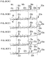
yarn feeders - (3-1) First, in a state wherein the
yarn feeder 20c stands by at a standby position leftward of the knit fabric as shown in (A) of FIG. 8, theyarn feeders - (3-2) Then, all needles on the left side of the last (in the example shown in (B) of FIG. (8), the rightmost end in the section Wb) needle P31 in the section Wb are advanced. Consequently, the
yarn 22a from theyarn feeder 20a is pushed down by the needles in the sections Wc and Wb while theyarn 22b from theyarn feeders 20b is pushed down by the needles in the section Wc. - (3-3) Then, the last needle P31 in the section Wb is advanced, and the
yarn feeder 20a is moved as indicated by an arrow mark as shown in (C) of FIG. 8. In particular, theyarn feeder 20a moves in the leftward direction from the position shown in (B) of FIG. 8 and passes the needle P31, whereafter it moves in the rightward direction again. During the rightward movement of theyarn feeder 20a, the needle P31 is advanced and retracted. Consequently, theyarn 22a from theyarn feeder 20a is confined by the needle P31. In this instance, since theyarn 22a is held down by the needles in the section Wb, it is confined with certainty by the needle P31. - (3-4) Then, all of the needles on the left side of the needle P31 from among the needles in the section Wb are retracted to release the
yarn 22a as shown in (D) of FIG. 8. However, theyarn 22a is confined with certainty by the needle P31 and accordingly held down by the needle P31. Simultaneously, the last needle in the section Wc is retracted and releases theyarn 22b. - (3-5) Then, the last needle P32 in the section Wc is advanced as shown in (E) of FIG. 8, and the
yarn feeder 20b is moved as indicated by an arrow mark. Consequently, theyarn 22b from theyarn feeder 20b is confined by the needle P32. In this instance, since theyarn 22b is held pushed down by the needles in the section Wc, theyarn 22b is confined with certainty by the needle P32. - (3-6) Then, all of the needles on the left side of the needle P32 from among the needles in the section Wc are retracted and release the
yarn 22b as shown in (F) of FIG. 8. However, theyarn 22b is confined with certainty by the needle P32, and accordingly, it is held down by the needle P32. - (3-7) Then, the
yarn feeders yarn - (3-8) Then, the needles P31 and P32 are retracted to release the
yarns - FIGS. 9 and 10 show an embodiment wherein the three-color intarsia knit fabric shown in FIG. 5, particularly, the courses B1 to Bn are knitted by a carriageless type flat knitting machine provided with three
yarn feeders - (4-1) First, the
yarn feeders - (4-2) Then, all of the needles in the sections Wc, Wb and Wa are successively advanced beginning with needles in the sections Wc, Wb and Wa nearest to the start point (in the example shown, the needles on the left side) as shown in (B) of FIG. 9. Consequently, the
yarn 22a from theyarn feeder 20a is pushed down by the needles in the sections Wc, Wb and Wa, theyarn 22b from theyarn feeder 20b is pushed down by the needles in the sections Wc and Wb, and theyarn 22c from theyarn feeder 20c is pushed down by the needles in the section Wc. - (4-3) Then, a right adjacent empty needle P40 to the section Wa is advanced as shown in (C) of FIG. 9, and the
yarn feeder 20a is moved as indicated by an arrow mark. Consequently, theyarn 22a from theyarn feeder 20a is engaged with and confined by the needle P40. In this instance, since theyarn 22a is held pushed down by the needles in the section Wa, theyarn 22a is confined with certainty by the needle P40. - (4-4) Then, all of the needles in the section Wa are retracted to release the
yarn 22a as shown in (D) of FIG. 9. However, theyarn 22a remains confined with certainty by the needle P40, and accordingly, it is held down by the needle P40. - (4-5) Then, a left end needle P41 in the section Wa is advanced as shown in (E) of FIG. 9, and the
yarn feeder 20b is moved as indicated by an arrow mark. Consequently, theyarn 22b from theyarn feeder 20b is engaged with and confined by the needle P41. In this instance, since theyarn 22b remains held down by the needles in the section Wb, it is confined with certainty by the needle P41. - (4-6) Then, all of the needles in the section Wb are retracted to release the
yarn 22b as shown in (F) of FIG. 9. However, theyarn 22b remains confined by the needle P41, and accordingly, it is held down by the needle P41. - (4-7) Then, a left end needle P42 in the section Wb is advanced as shown in (A) of FIG. 10, and the
yarn feeders 20c is moved as indicated by an arrow mark. Consequently, theyarn 22c from theyarn feeder 20c is engaged with and confined by the needle P42. In this instance, since theyarn 22c remains held down by the needles in the section Wc, it is confined with certainty by the needle P42. - (4-8) Then, all of the needles in the section Wc are retracted to release the
yarn 22c as shown in (B) of FIG. 10. However, theyarn 22c remains confined by the needle P42, and accordingly, it is held down by the needle P42. - (4-9) Then, the
yarn feeders yarns yarns
After theyarn feeders - (4-10) Then, the needles P40, P41 and P42 are retracted as shown in (D) of FIG. 10 to remove the
yarns - (4-11) Then, the
yarn feeders - While the embodiments described above relate to a method of knitting an intarsia knit fabric based on a plain stitch, the present invention can be applied also to a method of knitting other multicolor single knit fabrics.
- Where a rib structure is present at one end or both ends of a knit fabric in its widthwise direction, if a
yarn 22 from ayarn feeder 20 is connected to an end of aknit fabric 24 as shown in FIG. 12, theyarn 22 from theyarn feeder 20 is caught by a loop Q50 in the rib knit portion and the route of theyarn 22 becomes so high as indicated by an alternate long and short dashes line that often theyarn 22 cannot be caught by needles used to knit. In such a case, by using the following knitting process, theyarn 22 from theyarn feeder 20 is held down by the loop Q50 in the rib knit portion as indicated by an alternate long and two short dashes line in FIG. 11 and the route of theyarn 22 is lowered. - (5-1) First, when the relationship between the needles on the front and
rear needle beds needle bed 14 on the rear side are transferred to a corresponding needle on theneedle bed 12 on the front side as shown in (B) of FIG. 11. - (5-2) Then, the
yarn feeders yarns needle bed 14 on the rear side as in the embodiments described above. - (5-3) Then, as shown in (D) of FIG 11, the two loops Q50 of the rib structure transferred to the needle on the
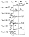
needle bed 12 on the front side are returned to the original needle on theneedle bed 14 on the rear side. Thereafter, knitting is started based on the procedure employed in the embodiments described above, particularly in the third embodiment. Consequently, as indicated by an alternate long and two short dashes line in FIG. 12, theyarns yarns - FIG. 13 illustrates an embodiment of a knitting method wherein, in order to end knitting of an intarsia knit fabric based only on a plain stitch on a carriageless type flat-knitting machine provided with three
yarn feeders reference numerals 241 and 242, respectively. - (6-1) First, the
yarn feeders yarn yarn feeders - (6-2) Then, after completion of knitting of the intarsia pattern portion, the
yarn feeders - (6-3) Then, the leftmost end needle P61 in the section Wb is driven to knit the two transit yarn portions in the knit fabric by a tuck stitch as shown in (D) of FIG. 13. In this instance, since the
yarns yarns - (6-4) Then, all of the needles in the sections Wa and Wb are retracted as shown in (E) of FIG. 13, whereafter the
yarn feeder 20c is moved from the right to the left as shown in (F) of FIG. 13 while the needles in the sections Wa and Wb are driven for knitting. Consequently, both of the sections Wa and Wb are knitted with theyarn 22c from theyarn feeder 20c. - While all of the third, fourth, fifth and sixth embodiments employ a carriageless type flat-knitting machine, the present invention can be performed also by a carriage type flat-knitting machine by moving the yarn feeders and the needles by means of a carriage.
- While all of the first to eighth embodiments described above relate to a method of knitting a multi-color single knit fabric on which a transit yarn portion appears, the present invention can be applied also to a knit fabric whose knitting width gradually increases as shown in FIG. 15. In particular, when the first course is knitted, a yarn from a yarn feeder is not knitted in a range from a portion thereof gripped by a gripping member to a knitting section. Consequently, the yarn from the yarn feeder forms a transit yarn portion in the range. In order to knit such a single knit fabric as just described, the
yarn 22 from theyarn feeder 20 should be engaged with, for example, the first needle in the knitting section after a plurality of needles corresponding to the non-knitting section are successively advanced beginning with the needle nearest to an end portion (start point 26) of the transit yarn portion. Thereafter, the needles in the non-knitting section advanced formerly are retracted. - FIG. 14 shows an embodiment of a
control unit 60 used for a carriageless type flat-knitting machine on which the knitting method described above is performed. - The carriageless type flat-knitting machine includes a plurality of actuators 621 to 62n provided corresponding to needles for individually moving the corresponding needles back and fourth, and a plurality of driving sources 641 to 64m provided corresponding to yarn feeders for individually and transversely reciprocating the corresponding yarn feeders. A DC linear motor is employed for the actuators. An electric motor with a speed reducer is used for the driving sources.
- The
control unit 60 includes a plurality of first controllers 661 to 66n individually provided corresponding to the actuators for controlling the movements and the positions of the corresponding actuators, and a plurality of second controllers 681 to 68m individually provided corresponding to the driving sources for controlling the rotations and positions of the corresponding driving sources. The first and second controllers 661 to 66n and 681 to 68m are individually provided by numbers equal to the numbers of the corresponding actuators and yarn feeders, respectively. - The first controllers 661 to 66n include memories 701 to 70n for storing operations of the first controllers based on a predetermined knitting plan, respectively. Similarly, the second controllers 681 to 68m include memories 721 to 72m for storing operations of the second controllers based on the predetermined knitting plan.
- The first and second controllers 661 to 66n and 681 to 68m are connected to a common
main controller 74 for providing timing signals of operations to the first controllers. The first controllers control the positions of the needles in synchronism with the operations of the second controllers. The second controllers control the positions of the yarn feeders. Themain controller 74 is connected to thememory 76 in which operations of themain controller 74 based on the predetermined knitting plan are stored. - Data to be stored into the memories 701 to 70n and 721 to 72m are data based on the predetermined knitting plan and are produced by a
knitting design computer 78 based on the predetermined knitting plan. The data produced by theknitting design computer 78 are either supplied directly to the individual memories by communication means such as a data communication line or supplied indirectly into the individual memories via some other communication means such as a tape, a disk or a bubble memory. - The data stored in the memories of the first controllers 661 to 66n are position data of the corresponding actuators and hence the corresponding needles, knit pattern data and some other necessary data for individual knitting courses. The data stored in the memories of the second controllers 681 to 68m are data of the corresponding yarn supply units and hence the widths and moving speeds of reciprocating motions of the yarn feeders and so forth for individual knitting courses and some other necessary data. The data stored in the
memory 76 of themain controller 74 are data in accordance with which selection of a yarn supply unit to be fed and selection of needles to be operated depending upon the positions of the yarn supply units are performed for each knitting course and some other necessary data. - The first and second controllers 661 to 66n and 681 to 68m operate the corresponding actuators and driving sources based on the data in the corresponding memories under the control of the
main controller 74. Consequently, the flat-knitting machine knits a multicolor single knit fabric having a predetermined knit pattern changing the feeding order of the plurality of yarn feeders in such a manner as described above.
Claims (4)
- A method of knitting a single knit fabric in which a yarn (22) from a yarn feeder (20) is not knitted but forms a transit yarn portion, comprising the steps of successively advancing a plurality of needles (16, 18) corresponding to a non-knitting section within which the yarn forms the transit yarn portion beginning with a needle on the side of a start point of the transit yarn portion to lower the yarn from said yarn feeder below the needles, and engaging the yarn from said yarn feeder by another needle on the side of said yarn feeder than the advanced yarns.
- A method of knitting a single knit fabric according to claim 1, wherein the needles (16, 18) which are successively advanced are needles on one or both of a needle bed (12 or 14) which takes part in knitting and another needle bed (14 or 12) which does not take part in knitting.
- A method of knitting a single knit fabric according to claim 1 or 2, wherein the needles (16, 18) which are successively advanced are all of those needles corresponding to the non-knitting section or every plurality of ones of those needles or else a plurality of ones of those needles farther by a plurality of needles than the start point of the transit yarn portion.
- A method of knitting a single knit fabric according to claim 1, 2 or 3, wherein the another needle (20) is the first needle of a knitting section in which the yarn from said yarn feeder (20) is knitted or the last needle in the non-knitting section, the last needle being a needle on a needle bed which does not take part in knitting.
Applications Claiming Priority (3)
| Application Number | Priority Date | Filing Date | Title |
|---|---|---|---|
| JP201796/95 | 1995-07-17 | ||
| JP7201796A JPH0931804A (en) | 1995-07-17 | 1995-07-17 | Knitting of single knit fabric |
| JP20179695 | 1995-07-17 |
Publications (2)
| Publication Number | Publication Date |
|---|---|
| EP0754792A1 true EP0754792A1 (en) | 1997-01-22 |
| EP0754792B1 EP0754792B1 (en) | 1999-10-20 |
Family
ID=16447083
Family Applications (1)
| Application Number | Title | Priority Date | Filing Date |
|---|---|---|---|
| EP96110312A Expired - Lifetime EP0754792B1 (en) | 1995-07-17 | 1996-06-26 | Method of knitting single knit fabric |
Country Status (4)
| Country | Link |
|---|---|
| US (1) | US5819558A (en) |
| EP (1) | EP0754792B1 (en) |
| JP (1) | JPH0931804A (en) |
| DE (1) | DE69604737T2 (en) |
Cited By (3)
| Publication number | Priority date | Publication date | Assignee | Title |
|---|---|---|---|---|
| GB2310220A (en) * | 1996-02-13 | 1997-08-20 | Tsudakoma Ind Co Ltd | Joining areas knitted side-by-side on a flat knitting machine |
| US6857294B2 (en) | 2001-05-25 | 2005-02-22 | Shima Seiki Manufacturing Limited | Method for knitting intarsia pattern knitting fabric and knitting program producing device therefor |
| CN107794635A (en) * | 2016-09-07 | 2018-03-13 | 株式会社岛精机制作所 | The weaving method of knitted fabric |
Families Citing this family (6)
| Publication number | Priority date | Publication date | Assignee | Title |
|---|---|---|---|---|
| EP1462555B1 (en) | 2001-11-26 | 2008-08-20 | Shima Seiki Mfg., Ltd | Method of knitting intersia pattern knitted fabric |
| US20070036770A1 (en) * | 2005-08-12 | 2007-02-15 | Wagner Darrell O | Biologic device for regulation of gene expression and method therefor |
| EP1972709A4 (en) * | 2005-11-17 | 2012-08-15 | Shima Seiki Mfg | METHOD AND DEVICE FOR CUTTING OR DEVICE KEEPING THE KNITTING PATCH ON A FLAT KNITTING MACHINE |
| KR101209645B1 (en) | 2006-03-20 | 2012-12-07 | 가부시키가이샤 시마세이키 세이사쿠쇼 | Method for knitting fabric and design device |
| CN108035061A (en) * | 2018-01-10 | 2018-05-15 | 海宁市中发纺织有限公司 | A kind of composite warp knitted fabric process equipment |
| US12209337B2 (en) * | 2019-11-07 | 2025-01-28 | Adidas Ag | Knitted garments having colored regions and textured elements and methods of forming the same |
Citations (4)
| Publication number | Priority date | Publication date | Assignee | Title |
|---|---|---|---|---|
| DE2636357A1 (en) * | 1976-08-12 | 1978-02-16 | Fauler Strickwarenfabrik Gmbh | Multicoloured Jacquard fabric - having pattern fabric overlaid on inner side with fabric knitted with second needle bed and joined along upper and lower edges |
| EP0164487A1 (en) * | 1984-05-22 | 1985-12-18 | COMET MARTINELLI S.r.l. | Flat bed knitting machine for manufacturing intarsia knitwork |
| EP0235987A1 (en) * | 1986-02-13 | 1987-09-09 | Asahi Kasei Kogyo Kabushiki Kaisha | Method for knitting a flat knitted fabric, a flat knitting machine and a novel flat knitted fabric knitted by said flat knitting machine |
| EP0679747A1 (en) * | 1994-04-28 | 1995-11-02 | Shima Seiki Mfg., Ltd. | Yarn guiding method and apparatus for flat knitting machine |
Family Cites Families (4)
| Publication number | Priority date | Publication date | Assignee | Title |
|---|---|---|---|---|
| DE170545C (en) * | ||||
| US782480A (en) * | 1902-10-24 | 1905-02-14 | Albin Benndorf | Straight-knitting machine. |
| GB190321660A (en) * | 1903-10-08 | 1903-11-12 | Lamson Pneumatic Tube Co | Improvements in Receiving Terminals for Pneumatic Despatch Apparatus |
| JPS6412855A (en) * | 1987-07-04 | 1989-01-17 | Shiro Yoshikawa | Thread winding type power storing method |
-
1995
- 1995-07-17 JP JP7201796A patent/JPH0931804A/en active Pending
-
1996
- 1996-06-26 EP EP96110312A patent/EP0754792B1/en not_active Expired - Lifetime
- 1996-06-26 DE DE69604737T patent/DE69604737T2/en not_active Expired - Fee Related
- 1996-07-15 US US08/680,177 patent/US5819558A/en not_active Expired - Fee Related
Patent Citations (5)
| Publication number | Priority date | Publication date | Assignee | Title |
|---|---|---|---|---|
| DE2636357A1 (en) * | 1976-08-12 | 1978-02-16 | Fauler Strickwarenfabrik Gmbh | Multicoloured Jacquard fabric - having pattern fabric overlaid on inner side with fabric knitted with second needle bed and joined along upper and lower edges |
| EP0164487A1 (en) * | 1984-05-22 | 1985-12-18 | COMET MARTINELLI S.r.l. | Flat bed knitting machine for manufacturing intarsia knitwork |
| EP0235987A1 (en) * | 1986-02-13 | 1987-09-09 | Asahi Kasei Kogyo Kabushiki Kaisha | Method for knitting a flat knitted fabric, a flat knitting machine and a novel flat knitted fabric knitted by said flat knitting machine |
| JPH0112855B2 (en) * | 1986-02-13 | 1989-03-02 | Asahi Chemical Ind | |
| EP0679747A1 (en) * | 1994-04-28 | 1995-11-02 | Shima Seiki Mfg., Ltd. | Yarn guiding method and apparatus for flat knitting machine |
Cited By (5)
| Publication number | Priority date | Publication date | Assignee | Title |
|---|---|---|---|---|
| GB2310220A (en) * | 1996-02-13 | 1997-08-20 | Tsudakoma Ind Co Ltd | Joining areas knitted side-by-side on a flat knitting machine |
| US5758518A (en) * | 1996-02-13 | 1998-06-02 | Tsudakoma Kogyo Kabushiki Kaisha | Method of forming transit yarn fastening portion |
| US6857294B2 (en) | 2001-05-25 | 2005-02-22 | Shima Seiki Manufacturing Limited | Method for knitting intarsia pattern knitting fabric and knitting program producing device therefor |
| CN107794635A (en) * | 2016-09-07 | 2018-03-13 | 株式会社岛精机制作所 | The weaving method of knitted fabric |
| CN107794635B (en) * | 2016-09-07 | 2019-08-09 | 株式会社岛精机制作所 | Knitted fabric weaving method |
Also Published As
| Publication number | Publication date |
|---|---|
| EP0754792B1 (en) | 1999-10-20 |
| JPH0931804A (en) | 1997-02-04 |
| DE69604737D1 (en) | 1999-11-25 |
| US5819558A (en) | 1998-10-13 |
| DE69604737T2 (en) | 2000-02-03 |
Similar Documents
| Publication | Publication Date | Title |
|---|---|---|
| EP1972706B1 (en) | Weft knitting machine capable of inserting warp and knitting method by that weft knitting machine | |
| JP5543780B2 (en) | Flat knitting machine and its yarn feeding method | |
| EP0754792B1 (en) | Method of knitting single knit fabric | |
| EP1995363B1 (en) | Method for knitting fabric and design device | |
| CN108018645B (en) | Plating knitting method and flat knitting machine used therefor | |
| EP1403409B1 (en) | Method of knitting intersia pattern knitting fabric and knitting program producing device therefor | |
| US5758518A (en) | Method of forming transit yarn fastening portion | |
| US7269975B2 (en) | Cam apparatus for knitting fabric | |
| US4909048A (en) | Method for producing intarsia knitted goods and flat-bed knitting machine for implementing the method | |
| US5275022A (en) | Process for the fully-fashioned knitting of intarsia jacquard fabric | |
| US4724685A (en) | Flat-bed knitting machine | |
| CN1086751C (en) | Method of weaving a knitwear on horizontal loom | |
| EP1652982B1 (en) | Flat knitting machine, and method of and apparatus for generating knitting program | |
| EP2369045B1 (en) | Knitted fabric, knitting method thereof and designing apparatus | |
| JP2005060857A5 (en) | ||
| JPS5842298B2 (en) | Method and device for knitting regular knitting pieces and regular intersia patterns | |
| CN114657685B (en) | Knitting system for flat knitting machine or braiding machine | |
| US6688140B2 (en) | Weft knitting machine with transfer mechanism and transferring method | |
| US3797278A (en) | Warp knitting machine | |
| JPH0931807A (en) | Knitting of plaiting knit fabric | |
| JPH0931802A (en) | Knitting of multicolored single knit fabric | |
| JP2000303327A (en) | Extra knitting method | |
| JPH1193044A (en) | Formation of twisted stitch | |
| JPH0931803A (en) | Knitting of pile knit fabric | |
| JPH10325055A (en) | Multi-colored single knitted fabric and its knitting |
Legal Events
| Date | Code | Title | Description |
|---|---|---|---|
| PUAI | Public reference made under article 153(3) epc to a published international application that has entered the european phase |
Free format text: ORIGINAL CODE: 0009012 |
|
| AK | Designated contracting states |
Kind code of ref document: A1 Designated state(s): CH DE FR GB IT LI |
|
| 17P | Request for examination filed |
Effective date: 19970207 |
|
| GRAG | Despatch of communication of intention to grant |
Free format text: ORIGINAL CODE: EPIDOS AGRA |
|
| GRAG | Despatch of communication of intention to grant |
Free format text: ORIGINAL CODE: EPIDOS AGRA |
|
| GRAH | Despatch of communication of intention to grant a patent |
Free format text: ORIGINAL CODE: EPIDOS IGRA |
|
| 17Q | First examination report despatched |
Effective date: 19990310 |
|
| GRAH | Despatch of communication of intention to grant a patent |
Free format text: ORIGINAL CODE: EPIDOS IGRA |
|
| GRAA | (expected) grant |
Free format text: ORIGINAL CODE: 0009210 |
|
| AK | Designated contracting states |
Kind code of ref document: B1 Designated state(s): CH DE FR GB IT LI |
|
| REG | Reference to a national code |
Ref country code: CH Ref legal event code: EP |
|
| REG | Reference to a national code |
Ref country code: CH Ref legal event code: NV Representative=s name: R. A. EGLI & CO. PATENTANWAELTE |
|
| REF | Corresponds to: |
Ref document number: 69604737 Country of ref document: DE Date of ref document: 19991125 |
|
| ET | Fr: translation filed | ||
| ITF | It: translation for a ep patent filed | ||
| PG25 | Lapsed in a contracting state [announced via postgrant information from national office to epo] |
Ref country code: LI Free format text: LAPSE BECAUSE OF NON-PAYMENT OF DUE FEES Effective date: 20000630 Ref country code: CH Free format text: LAPSE BECAUSE OF NON-PAYMENT OF DUE FEES Effective date: 20000630 |
|
| PLBE | No opposition filed within time limit |
Free format text: ORIGINAL CODE: 0009261 |
|
| STAA | Information on the status of an ep patent application or granted ep patent |
Free format text: STATUS: NO OPPOSITION FILED WITHIN TIME LIMIT |
|
| 26N | No opposition filed | ||
| REG | Reference to a national code |
Ref country code: CH Ref legal event code: PL |
|
| PGFP | Annual fee paid to national office [announced via postgrant information from national office to epo] |
Ref country code: FR Payment date: 20010611 Year of fee payment: 6 |
|
| PGFP | Annual fee paid to national office [announced via postgrant information from national office to epo] |
Ref country code: DE Payment date: 20010618 Year of fee payment: 6 |
|
| PGFP | Annual fee paid to national office [announced via postgrant information from national office to epo] |
Ref country code: GB Payment date: 20010620 Year of fee payment: 6 |
|
| REG | Reference to a national code |
Ref country code: GB Ref legal event code: IF02 |
|
| PG25 | Lapsed in a contracting state [announced via postgrant information from national office to epo] |
Ref country code: GB Free format text: LAPSE BECAUSE OF NON-PAYMENT OF DUE FEES Effective date: 20020626 |
|
| PG25 | Lapsed in a contracting state [announced via postgrant information from national office to epo] |
Ref country code: DE Free format text: LAPSE BECAUSE OF NON-PAYMENT OF DUE FEES Effective date: 20030101 |
|
| GBPC | Gb: european patent ceased through non-payment of renewal fee |
Effective date: 20020626 |
|
| PG25 | Lapsed in a contracting state [announced via postgrant information from national office to epo] |
Ref country code: FR Free format text: LAPSE BECAUSE OF NON-PAYMENT OF DUE FEES Effective date: 20030228 |
|
| REG | Reference to a national code |
Ref country code: FR Ref legal event code: ST |
|
| PG25 | Lapsed in a contracting state [announced via postgrant information from national office to epo] |
Ref country code: IT Free format text: LAPSE BECAUSE OF NON-PAYMENT OF DUE FEES;WARNING: LAPSES OF ITALIAN PATENTS WITH EFFECTIVE DATE BEFORE 2007 MAY HAVE OCCURRED AT ANY TIME BEFORE 2007. THE CORRECT EFFECTIVE DATE MAY BE DIFFERENT FROM THE ONE RECORDED. Effective date: 20050626 |