EP0754780B1 - Process for de-silvering a silver-containing solution - Google Patents
Process for de-silvering a silver-containing solution Download PDFInfo
- Publication number
- EP0754780B1 EP0754780B1 EP19950201953 EP95201953A EP0754780B1 EP 0754780 B1 EP0754780 B1 EP 0754780B1 EP 19950201953 EP19950201953 EP 19950201953 EP 95201953 A EP95201953 A EP 95201953A EP 0754780 B1 EP0754780 B1 EP 0754780B1
- Authority
- EP
- European Patent Office
- Prior art keywords
- cathode
- process according
- potential
- current density
- silvering
- Prior art date
- Legal status (The legal status is an assumption and is not a legal conclusion. Google has not performed a legal analysis and makes no representation as to the accuracy of the status listed.)
- Expired - Lifetime
Links
- 229910052709 silver Inorganic materials 0.000 title claims description 87
- 239000004332 silver Substances 0.000 title claims description 87
- BQCADISMDOOEFD-UHFFFAOYSA-N Silver Chemical compound [Ag] BQCADISMDOOEFD-UHFFFAOYSA-N 0.000 title claims description 86
- 238000000034 method Methods 0.000 title claims description 52
- 230000008569 process Effects 0.000 title claims description 46
- 238000009792 diffusion process Methods 0.000 claims description 64
- 239000011521 glass Substances 0.000 claims description 11
- 238000007086 side reaction Methods 0.000 claims description 10
- 230000004044 response Effects 0.000 claims description 4
- 239000000243 solution Substances 0.000 description 51
- 239000007788 liquid Substances 0.000 description 12
- 239000003792 electrolyte Substances 0.000 description 8
- 230000000607 poisoning effect Effects 0.000 description 7
- 150000001875 compounds Chemical class 0.000 description 6
- 231100000572 poisoning Toxicity 0.000 description 6
- LSNNMFCWUKXFEE-UHFFFAOYSA-L sulfite Chemical compound [O-]S([O-])=O LSNNMFCWUKXFEE-UHFFFAOYSA-L 0.000 description 6
- 239000000463 material Substances 0.000 description 5
- 238000011084 recovery Methods 0.000 description 5
- 230000009467 reduction Effects 0.000 description 5
- 239000010935 stainless steel Substances 0.000 description 5
- 229910001220 stainless steel Inorganic materials 0.000 description 5
- 238000000151 deposition Methods 0.000 description 4
- 238000007747 plating Methods 0.000 description 4
- 239000003381 stabilizer Substances 0.000 description 4
- 238000013019 agitation Methods 0.000 description 3
- 230000008859 change Effects 0.000 description 3
- 230000008021 deposition Effects 0.000 description 3
- 230000000694 effects Effects 0.000 description 3
- 239000012811 non-conductive material Substances 0.000 description 3
- 238000007789 sealing Methods 0.000 description 3
- -1 sulphite ions Chemical class 0.000 description 3
- YXIWHUQXZSMYRE-UHFFFAOYSA-N 1,3-benzothiazole-2-thiol Chemical class C1=CC=C2SC(S)=NC2=C1 YXIWHUQXZSMYRE-UHFFFAOYSA-N 0.000 description 2
- UFHFLCQGNIYNRP-UHFFFAOYSA-N Hydrogen Chemical compound [H][H] UFHFLCQGNIYNRP-UHFFFAOYSA-N 0.000 description 2
- CWRVKFFCRWGWCS-UHFFFAOYSA-N Pentrazole Chemical compound C1CCCCC2=NN=NN21 CWRVKFFCRWGWCS-UHFFFAOYSA-N 0.000 description 2
- 229910021607 Silver chloride Inorganic materials 0.000 description 2
- RTAQQCXQSZGOHL-UHFFFAOYSA-N Titanium Chemical compound [Ti] RTAQQCXQSZGOHL-UHFFFAOYSA-N 0.000 description 2
- 229940075397 calomel Drugs 0.000 description 2
- 238000005260 corrosion Methods 0.000 description 2
- 230000007797 corrosion Effects 0.000 description 2
- 230000003247 decreasing effect Effects 0.000 description 2
- ZOMNIUBKTOKEHS-UHFFFAOYSA-L dimercury dichloride Chemical compound Cl[Hg][Hg]Cl ZOMNIUBKTOKEHS-UHFFFAOYSA-L 0.000 description 2
- 238000003487 electrochemical reaction Methods 0.000 description 2
- 239000001257 hydrogen Substances 0.000 description 2
- 229910052739 hydrogen Inorganic materials 0.000 description 2
- 230000002401 inhibitory effect Effects 0.000 description 2
- 238000012423 maintenance Methods 0.000 description 2
- 239000000203 mixture Substances 0.000 description 2
- 238000012986 modification Methods 0.000 description 2
- 230000004048 modification Effects 0.000 description 2
- BASFCYQUMIYNBI-UHFFFAOYSA-N platinum Chemical compound [Pt] BASFCYQUMIYNBI-UHFFFAOYSA-N 0.000 description 2
- 238000012545 processing Methods 0.000 description 2
- HKZLPVFGJNLROG-UHFFFAOYSA-M silver monochloride Chemical compound [Cl-].[Ag+] HKZLPVFGJNLROG-UHFFFAOYSA-M 0.000 description 2
- 239000004094 surface-active agent Substances 0.000 description 2
- DHCDFWKWKRSZHF-UHFFFAOYSA-L thiosulfate(2-) Chemical compound [O-]S([S-])(=O)=O DHCDFWKWKRSZHF-UHFFFAOYSA-L 0.000 description 2
- YHMYGUUIMTVXNW-UHFFFAOYSA-N 1,3-dihydrobenzimidazole-2-thione Chemical class C1=CC=C2NC(S)=NC2=C1 YHMYGUUIMTVXNW-UHFFFAOYSA-N 0.000 description 1
- GGZHVNZHFYCSEV-UHFFFAOYSA-N 1-Phenyl-5-mercaptotetrazole Chemical compound SC1=NN=NN1C1=CC=CC=C1 GGZHVNZHFYCSEV-UHFFFAOYSA-N 0.000 description 1
- JAAIPIWKKXCNOC-UHFFFAOYSA-N 1h-tetrazol-1-ium-5-thiolate Chemical class SC1=NN=NN1 JAAIPIWKKXCNOC-UHFFFAOYSA-N 0.000 description 1
- HAZJTCQWIDBCCE-UHFFFAOYSA-N 1h-triazine-6-thione Chemical class SC1=CC=NN=N1 HAZJTCQWIDBCCE-UHFFFAOYSA-N 0.000 description 1
- PHPYXVIHDRDPDI-UHFFFAOYSA-N 2-bromo-1h-benzimidazole Chemical class C1=CC=C2NC(Br)=NC2=C1 PHPYXVIHDRDPDI-UHFFFAOYSA-N 0.000 description 1
- AYPSHJCKSDNETA-UHFFFAOYSA-N 2-chloro-1h-benzimidazole Chemical class C1=CC=C2NC(Cl)=NC2=C1 AYPSHJCKSDNETA-UHFFFAOYSA-N 0.000 description 1
- KRTDQDCPEZRVGC-UHFFFAOYSA-N 2-nitro-1h-benzimidazole Chemical class C1=CC=C2NC([N+](=O)[O-])=NC2=C1 KRTDQDCPEZRVGC-UHFFFAOYSA-N 0.000 description 1
- JSIAIROWMJGMQZ-UHFFFAOYSA-N 2h-triazol-4-amine Chemical class NC1=CNN=N1 JSIAIROWMJGMQZ-UHFFFAOYSA-N 0.000 description 1
- CBHTTYDJRXOHHL-UHFFFAOYSA-N 2h-triazolo[4,5-c]pyridazine Chemical class N1=NC=CC2=C1N=NN2 CBHTTYDJRXOHHL-UHFFFAOYSA-N 0.000 description 1
- OCVLSHAVSIYKLI-UHFFFAOYSA-N 3h-1,3-thiazole-2-thione Chemical class SC1=NC=CS1 OCVLSHAVSIYKLI-UHFFFAOYSA-N 0.000 description 1
- UTMDJGPRCLQPBT-UHFFFAOYSA-N 4-nitro-1h-1,2,3-benzotriazole Chemical class [O-][N+](=O)C1=CC=CC2=NNN=C12 UTMDJGPRCLQPBT-UHFFFAOYSA-N 0.000 description 1
- LRUDIIUSNGCQKF-UHFFFAOYSA-N 5-methyl-1H-benzotriazole Chemical compound C1=C(C)C=CC2=NNN=C21 LRUDIIUSNGCQKF-UHFFFAOYSA-N 0.000 description 1
- HMJGQFMTANUIEW-UHFFFAOYSA-N 5-phenylsulfanyl-2h-tetrazole Chemical compound C=1C=CC=CC=1SC=1N=NNN=1 HMJGQFMTANUIEW-UHFFFAOYSA-N 0.000 description 1
- GIQKIFWTIQDQMM-UHFFFAOYSA-N 5h-1,3-oxazole-2-thione Chemical compound S=C1OCC=N1 GIQKIFWTIQDQMM-UHFFFAOYSA-N 0.000 description 1
- 229910001316 Ag alloy Inorganic materials 0.000 description 1
- OKTJSMMVPCPJKN-UHFFFAOYSA-N Carbon Chemical compound [C] OKTJSMMVPCPJKN-UHFFFAOYSA-N 0.000 description 1
- ISLYUUGUJKSGDZ-UHFFFAOYSA-N OC1=CC=NC2=NC=NN12 Chemical class OC1=CC=NC2=NC=NN12 ISLYUUGUJKSGDZ-UHFFFAOYSA-N 0.000 description 1
- ZMZDMBWJUHKJPS-UHFFFAOYSA-M Thiocyanate anion Chemical compound [S-]C#N ZMZDMBWJUHKJPS-UHFFFAOYSA-M 0.000 description 1
- 229910052787 antimony Inorganic materials 0.000 description 1
- WATWJIUSRGPENY-UHFFFAOYSA-N antimony atom Chemical compound [Sb] WATWJIUSRGPENY-UHFFFAOYSA-N 0.000 description 1
- 230000008901 benefit Effects 0.000 description 1
- XHLMRAUSOZPJEM-UHFFFAOYSA-N benzenesulfonothioamide Chemical compound NS(=O)(=S)C1=CC=CC=C1 XHLMRAUSOZPJEM-UHFFFAOYSA-N 0.000 description 1
- IOJUPLGTWVMSFF-UHFFFAOYSA-N benzothiazole Chemical class C1=CC=C2SC=NC2=C1 IOJUPLGTWVMSFF-UHFFFAOYSA-N 0.000 description 1
- 150000001565 benzotriazoles Chemical class 0.000 description 1
- 230000015572 biosynthetic process Effects 0.000 description 1
- 239000006172 buffering agent Substances 0.000 description 1
- 230000003139 buffering effect Effects 0.000 description 1
- 239000006227 byproduct Substances 0.000 description 1
- 150000001661 cadmium Chemical class 0.000 description 1
- 239000010406 cathode material Substances 0.000 description 1
- 239000003795 chemical substances by application Substances 0.000 description 1
- 239000008139 complexing agent Substances 0.000 description 1
- 239000004020 conductor Substances 0.000 description 1
- 238000012937 correction Methods 0.000 description 1
- 238000005137 deposition process Methods 0.000 description 1
- 230000005684 electric field Effects 0.000 description 1
- 239000008151 electrolyte solution Substances 0.000 description 1
- 239000000839 emulsion Substances 0.000 description 1
- 238000002474 experimental method Methods 0.000 description 1
- 229910002804 graphite Inorganic materials 0.000 description 1
- 239000010439 graphite Substances 0.000 description 1
- ZMZDMBWJUHKJPS-UHFFFAOYSA-N hydrogen thiocyanate Natural products SC#N ZMZDMBWJUHKJPS-UHFFFAOYSA-N 0.000 description 1
- 230000002706 hydrostatic effect Effects 0.000 description 1
- AKCUHGBLDXXTOM-UHFFFAOYSA-N hydroxy-oxo-phenyl-sulfanylidene-$l^{6}-sulfane Chemical compound SS(=O)(=O)C1=CC=CC=C1 AKCUHGBLDXXTOM-UHFFFAOYSA-N 0.000 description 1
- WYASEAQTEQVOJE-UHFFFAOYSA-N hydroxy-phenyl-sulfanylidene-$l^{4}-sulfane Chemical compound OS(=S)C1=CC=CC=C1 WYASEAQTEQVOJE-UHFFFAOYSA-N 0.000 description 1
- 239000004615 ingredient Substances 0.000 description 1
- 238000004519 manufacturing process Methods 0.000 description 1
- 238000005259 measurement Methods 0.000 description 1
- QSHDDOUJBYECFT-UHFFFAOYSA-N mercury Chemical compound [Hg] QSHDDOUJBYECFT-UHFFFAOYSA-N 0.000 description 1
- 229910052753 mercury Inorganic materials 0.000 description 1
- 229910052751 metal Inorganic materials 0.000 description 1
- 239000002184 metal Substances 0.000 description 1
- 238000013508 migration Methods 0.000 description 1
- 230000005012 migration Effects 0.000 description 1
- 238000012544 monitoring process Methods 0.000 description 1
- 150000004957 nitroimidazoles Chemical class 0.000 description 1
- 229910000510 noble metal Inorganic materials 0.000 description 1
- 239000003002 pH adjusting agent Substances 0.000 description 1
- 229910052697 platinum Inorganic materials 0.000 description 1
- 239000002574 poison Substances 0.000 description 1
- 231100000614 poison Toxicity 0.000 description 1
- HBCQSNAFLVXVAY-UHFFFAOYSA-N pyrimidine-2-thiol Chemical class SC1=NC=CC=N1 HBCQSNAFLVXVAY-UHFFFAOYSA-N 0.000 description 1
- BDJXVNRFAQSMAA-UHFFFAOYSA-N quinhydrone Chemical compound OC1=CC=C(O)C=C1.O=C1C=CC(=O)C=C1 BDJXVNRFAQSMAA-UHFFFAOYSA-N 0.000 description 1
- 229940052881 quinhydrone Drugs 0.000 description 1
- 238000011946 reduction process Methods 0.000 description 1
- 238000011160 research Methods 0.000 description 1
- 239000008237 rinsing water Substances 0.000 description 1
- 230000000630 rising effect Effects 0.000 description 1
- 150000003839 salts Chemical class 0.000 description 1
- 239000003352 sequestering agent Substances 0.000 description 1
- 230000000087 stabilizing effect Effects 0.000 description 1
- 238000003860 storage Methods 0.000 description 1
- JJJPTTANZGDADF-UHFFFAOYSA-N thiadiazole-4-thiol Chemical class SC1=CSN=N1 JJJPTTANZGDADF-UHFFFAOYSA-N 0.000 description 1
- 239000010936 titanium Substances 0.000 description 1
- 229910052719 titanium Inorganic materials 0.000 description 1
- 239000000080 wetting agent Substances 0.000 description 1
Images


Classifications
-
- C—CHEMISTRY; METALLURGY
- C25—ELECTROLYTIC OR ELECTROPHORETIC PROCESSES; APPARATUS THEREFOR
- C25C—PROCESSES FOR THE ELECTROLYTIC PRODUCTION, RECOVERY OR REFINING OF METALS; APPARATUS THEREFOR
- C25C7/00—Constructional parts, or assemblies thereof, of cells; Servicing or operating of cells
- C25C7/06—Operating or servicing
-
- C—CHEMISTRY; METALLURGY
- C25—ELECTROLYTIC OR ELECTROPHORETIC PROCESSES; APPARATUS THEREFOR
- C25C—PROCESSES FOR THE ELECTROLYTIC PRODUCTION, RECOVERY OR REFINING OF METALS; APPARATUS THEREFOR
- C25C1/00—Electrolytic production, recovery or refining of metals by electrolysis of solutions
- C25C1/20—Electrolytic production, recovery or refining of metals by electrolysis of solutions of noble metals
Definitions
- the present invention relates to a process and apparatus for the electrolytic recovery of silver from solutions containing silver, in particular used photographic solutions such as fixing solutions.
- Electrolytic silver recovery from used photographic solutions is a common way to extend the life of such solutions.
- An apparatus for the electrolytic recovery of silver from solutions containing silver is known from European patent application EPA 93200427.8 (Agfa-Gevaert NV) filed 16 February 1993.
- the apparatus comprises an electrolytic cell having an anode and a cathode, and electrical power supply control means for controlling the supply of electrical power to the anode and the cathode.
- the control of the electrochemical process taking place at the anode and the cathode is important in the silver recovery process. If too high a potential difference is applied, side reactions can occur, depending upon the nature of the silver-containing solution, leading to unwanted by-products.
- the conditions required for optimum de-silvering depend upon a number of factors including the cathode potential, the concentration of silver in the silver-containing solution, the pH of the silver-containing solution (usually within the range of from 3.5 to 6.0) and the condition of the cathode.
- the cathode potential for a given silver concentration, pH and cathode condition, there is an ideal cathode potential, or narrow range of cathode potentials, which provides fast deposition, good adherence of the silver to the cathode and a low level of side reactions. Outside these optimum conditions, these objectives may not reliably be met.
- the concentration of silver in the silver-containing solution changes as silver is deposited and fresh solution is added, the pH of the solution is unknown or varies in an unpredictable manner and the condition of the cathode may change. It has not therefore been possible to set the electrolytic cell to the optimum de-silvering conditions and to maintain optimum conditions as the de-silvering continues.
- the potential difference between the anode and the cathode is kept constant as the de-silvering progresses.
- the disadvantage of this method is that the potential difference between the cathode and the solution is not controlled.
- the electrochemical reactions taking place at the cathode are therefore uncontrolled, depending on a large number of factors such as the size of the anode, agitation in the neighbourhood of the anode, the presence or absence of components in the solution which can be oxidised and the ease with which they can be oxidised (e.g. SO 3 -- and S 2 O 3 -- ), the ohmic potential drop in the cell and therefore also the cell geometry and current density, and the current through the cell.
- a reference electrode is included in the electrolytic cell and the potential difference between the cathode and the reference electrode is kept constant. This allows complete control over the cathode potential. This method of operation is therefore widely preferred, since it is the cathode potential which determines electrochemical reactions which take place in a fixer of a certain composition.
- the influence of the anode potential (and largely also the ohmic potential contributions) are excluded. This enables the initial cathode potential to be set at a level where bad silver adhesion, side reactions and sulphiding of the cathode can be avoided, independently of the anode potential.
- a reference electrode makes the equipment more reliable, since factors such as the current density at the anode, the surface state of the anode, over-potential at the anode (caused by changes in solution composition), and ohmic potential drops no longer influence the cathode potential.
- factors such as the current density at the anode, the surface state of the anode, over-potential at the anode (caused by changes in solution composition), and ohmic potential drops no longer influence the cathode potential.
- the de-silvering process proceeds by depositing silver upon the cathode. If the silver does not adhere strongly to the cathode, there is a risk that it will become detached therefrom, especially as the weight of silver deposited increases and especially in continuously operated cells which have a constant flow of electrolyte solution passing over the cathode. The detached silver may fall to the bottom of the cell where it eventually builds up to a level which may cause a short circuit between the anode and the cathode. Alternatively or additionally the detached silver is flushed out of the cell with the electrolyte liquid. In either case the de-silvering of the solution is not optimally achieved. Optimum user-friendliness is only achievable when the deposited silver is well attached to the cathode.
- the potentiostatic control takes no account of all the changes which may occur in the condition of the cathode.
- the silver content of the bath to be de-silvered is high (for example >3 g/l) and the de-silvering apparatus as such is working correctly, no silver becomes deposited on the cathode.
- This last effect is thought to be due to "cathode poisoning".
- Poisoning occurs when components present in the solution block the cathode reduction process. Not all cases of cathode poisoning are understood, but certain components which are present in the developer or which are flushed out of the film may be the cause.
- a number of photographic stabilisers exhibit this effect, such as PMT (phenyl mercapto tetrazol).
- EP-A-201837 describes the electrolytic recovery of silver in a cell which is operated at the plateau of the potential difference/current curve for the cell, that is at that point where the current is determined by the speed of diffusion (migration or mass transport) of silver to the cathode surface. This condition is referred to herein as the diffusion limitation current.
- the optimum current for obtaining good silver adhesion while not corresponding to the diffusion limitation current, is nevertheless related thereto, and in particular that the optimum current is less than the diffusion limitation current.
- a process for de-silvering a silver-containing solution in an electrolytic cell having an anode and a cathode characterised by the following steps:
- the invention also provides, according to a second aspect, an apparatus for de-silvering a silver-containing solution comprising an electrolytic cell having an anode and a cathode, characterised by :
- the diffusion limitation current density is greatly dependant upon the surface structure of the cathode. New polished cathodes tend to exhibit lower diffusion limitation current densities than cathodes where silver has already been deposited thereon. The diffusion limitation current density will tend to increase as the silver is being deposited, especially at the beginning of the lifetime of the cathode, but this increase is unpredictable.
- the surface structure of the cathode is also dependant on the plating history of the cathode. Agitation of the solution may vary with time, especially in practical situations where filters in the solution supply circuit clog over time, supply tubes may bend or kink and as the cathode surface grows the geometry of the cell will change.
- Steps (a) and (b) of the process are preferably performed in respect of the same cathode surface, it being less preferred that a different cathode or only part of the surface of the cathode be used to estimate diffusion limitation current density.
- a different cathode or only part of the surface of the cathode be used to estimate diffusion limitation current density.
- the comparison needs to be in respect of current densities and the area of the cathode used for de-silvering needs to be known in order to derive the total current which needs to be applied thereto.
- estimating the diffusion limitation current density of the cell may be carried out by potentiostatically setting the cathode to a predetermined cathode potential and measuring the current flow through the electrolytic cell.
- the diffusion limitation current density is estimated by measuring the current density at a specified i.e. predetermined potential.
- the predetermined cathode potential may be set relative to the anode or, more preferably relative to a third electrode, not being the cathode nor the anode.
- This third electrode may be a reference electrode.
- Reference electrodes suitable for use in electrolytic de-silvering include standard calomel type electrodes or Ag/AgCl type electrodes, but we particularly prefer the use of a pH sensitive electrode such as a glass electrode, a hydrogen electrode, a quinhydrone electrode and an antimony electrode, most especially a glass electrode which is relatively maintenance free and which is moreover insensitive to hydrostatic pressure variations.
- the predetermined cathode potential may be from -510 mV to -590 mV, such as from -530 mV to -560 mV, versus the glass electrode. When set to this potential, the silver plating current will be diffusion limited, except where the pH is low (such as below 4.5) when more negative cathode potentials are preferred.
- the predetermined cathode potential must not be so negative that substantial side reactions occur, which would lead to an over-estimate of the diffusion limitation current density. Except where the reference electrode is a pH electrode, this is particularly the case for low pH fixers where sulphite reduction tends to occur at less negative cathode potentials. At higher pH values, the sulphite reduction potential is more negative and the sulphite reduction current also tends to be lower.
- the cathode may be set to a potential where no more than 40%, most preferably no more than 20%, of the current at the cathode may be consumed by side reactions, as measured from the efficiency of the silver deposition process.
- the diffusion limitation current density is estimated by potentiostatically setting the cathode potential to a predetermined value, it is preferable to select a value which is more negative than the de-poisoning potential of the cathode, since otherwise under-estimation of the diffusion limitation current, and therefore too slow de-silvering, may occur.
- the diffusion limitation current is not substantially affected by poisoning.
- poisoning will cause the diffusion limitation current density to be under-estimated. This will, for example, be the case when the de-poisoning potential is equal to the cathode potential during the estimation of the diffusion limitation current density.
- a short current surge may be applied to activate the cathode.
- This current surge may be applied in the normal plating step, but preferably, it is given during the step where the diffusion limitation current density is estimated.
- a current surge may be applied to the cathode during which the cathode potential is at least 20 mV more negative than the predetermined cathode potential for a period of less than 10 seconds, most preferably at least 50 mV more negative than the predetermined cathode potential for a period of less than 3 seconds.
- the diffusion limitation current density may be estimated from the responses to known potential variations applied to the cathode, as described in EP-A-201837 referred to above.
- the diffusion limitation current density may be estimated from the shape of current-potential curves. This is possible by periodically measuring the current-potential characteristic of the de-silvering cell under actual de-silvering conditions.
- the current-potential characteristic may be the curve of current versus 1) potential difference between the cathode and a third electrode, 2) potential difference between the cathode and the anode, or 3) the potential difference between the anode and a third electrode not being the cathode.
- the diffusion limitation current can, for example, be determined by identifying the cell current at the cathode potential when the second derivative of the current-potential characteristic is zero and the first derivative is minimal.
- the third electrode may be a standard calomel electrode or a silver/silver chloride electrode, a pH sensitive reference electrode, especially a glass electrode, or a silver electrode (used for measuring the rest potential). Low maintenance electrodes with good durability are preferred.
- Estimating the diffusion limitation current density of the cell may be carried out at a frequency sufficiently high that the silver content of the silver-containing solution falls by less than 50%, most preferably by less than 20%, in the immediately preceding de-silvering step.
- the diffusion limitation current density may be estimated from the shape of the curve of current density versus potential difference between the anode and the cathode or from the shape of the curve of current density versus potential difference between the cathode and a third electrode, other than the anode and the cathode.
- Estimating the diffusion limitation current density of the cell may be carried out automatically, such as by an intelligent control device which forms part of, or may be connected to the apparatus.
- Steps (a) and (b) may be performed alternately, that is, estimation the diffusion limitation current density of the cell may be repeated after each de-silvering step and the sequence may be continued.
- the de-silvering current density is lower than the diffusion limitation current density by a predetermined fraction, which may, for example, be from 10% to 90%, such as from 30% to 80% of the diffusion limitation current density.
- the de-silvering current may be controlled potentiostatically, that is the de-silvering cathode potential may be so controlled as to not vary by any more than ⁇ 15%.
- the de-silvering current may be controlled galvanostatically to a substantially stable value, that is the de-silvering current may be so controlled as to not vary by any more than ⁇ 20%.
- Galvanostatic control or a hybrid of galvanostatic and potentiostatic control, is preferred for two reasons. Firstly, in the case of poisoned cathodes, the current-potential characteristic may be very steep, which makes potentiostatic control liable to instabilities. Secondly, again in the case of poisoned cathodes, diffusion limitation current density is preferably estimated at a potential more negative than the de-poisoning potential, so that there is little or no interference from the poisoning of the cathode.
- the de-silvering current density is controlled potentiostatically, it can happen that the cathode starts to poison and that the current drops.
- the cathode potential will automatically be made more negative as the cathode starts to be poisoned.
- the control of the de-silvering current density is carried out by a hybrid of potentiostatic and galvanostatic control.
- the anode-cathode potential difference is slowly decreased.
- the potential is measured and potentiostatic control takes over with the target potential equal to that measured potential.
- the measured current is compared with the target current (in this case 60% of the diffusion limitation current density). If the current value is too low or too high, the target potential for the potentiostatic control is adjusted accordingly.
- the time taken for estimating the diffusion limitation current density of the cell may be from 1 to 25%, such as from 2% to 10%, of the total de-silvering time, that is of the total time taken for both steps (a) and (b).
- the silver-containing solution may be selected from photographic fixing and bleach-fixing solutions.
- the silver concentration in the silver-containing solution is typically from 0.1 g/l to 5 g/l.
- the process of the invention is particularly effective if the fixing solution has a volume of less than 100 ml/g, most preferably less than 40 ml/g of silver to be fixed thereby, because at low replenishment rates, the importance of unwanted side reactions becomes greater.
- the silver-containing solutions which can be de-silvered using the present invention include any solution containing silver complexing agents, e.g. thiosulphate or thiocyanate, sulphite ions and free and complexed silver as a result of the fixing process.
- the apparatus can also be used with rinsing water or concentrated or diluted used fixing solutions, possibly contaminated with carried-over developer. Apart from the essential ingredients, such solutions will often also contain wetting agents, buffering agents, sequestering agents and pH adjusting agents.
- the silver-containing solution may comprise compounds preventing the formation of fog or stabilizing the photographic characteristics during the production or storage of photographic elements or during the photographic treatment thereof.
- Suitable examples are inter alia the heterocyclic nitrogen-containing compounds such as benzothiazolium salts, nitroimidazoles, nitrobenzimidazoles, chlorobenzimidazoles, bromobenzimidazoles, mercaptothiazoles, mercaptobenzothiazoles, mercaptobenzimidazoles, mercaptothiadiazoles, aminotriazoles, benzotriazoles (preferably 5-methyl-benzotriazole), nitrobenzotriazoles, mercaptotetrazoles, in particular 1-phenyl-5-mercapto-tetrazole, mercaptopyrimidines, mercaptotriazines, benzothiazoline-2-thione, oxazoline-thione, triazaindenes, tetrazaindenes and pentazaindenes, especially those described by Birr in Z.
- heterocyclic nitrogen-containing compounds such as benzothiazolium salts, nitroimidazoles, nitro
- the process is particularly applicable in cases of low replenishment rates, because components carried over from the developer for example and components which are flushed out of the film (such as stabilizers, surfactants and sensitizers), are more concentrated.
- components carried over from the developer for example and components which are flushed out of the film such as stabilizers, surfactants and sensitizers
- surfactants may aggravate the poisoning effects of stabilizers such as PMT.
- the de-silvering process can be carried out batch-wise or continuously, the apparatus being connected to the fixing solution forming part of a continuous processing sequence.
- the apparatus according to the invention may be designed to be operated manually, automatically or automatically with manual over-ride.
- the material used for the anode is not especially critical, although platinated titanium is usually used. Platinum, graphite and noble metals are alternatives.
- the anode may be in the form of a rod, located at the axis of the electrolytic cell, where this is in cylindrical form.
- the cathode may be formed from a generally flat sheet of flexible material, an electrically conductive surface being provided on one major face thereof, securing means being provided to enable the sheet to be folded into and secured in an open circular cross-sectional configuration.
- the cathode preferably ideally has a frusto-conical cross-section, with its larger radius end uppermost, that is towards the circular upper opening of the electrolyte cell. This configuration enables easy removal of the cathode even after a silver deposit has built up there-on after use.
- Usable cathode materials include stainless steel, silver and silver alloys, and other conductive materials, the non-silver containing materials being preferred from the point of view of costs, while the silver containing materials cause fewer starting-up problems.
- the positioning of the reference electrode is important to the de-silvering process. While in principle the electrode would be best placed between the cathode and the anode, as close as possible to the cathode, this may cause troubles as more and more silver is deposited on the cathode, which is thus growing thicker. When the reference electrode is placed further from the cathode, say 20 mm therefrom, ohmic potential drops will cause the potentiostatic de-silvering not to be truly potentiostatic. It has therefore been proposed to place the reference electrode on the far side of the cathode from the anode, but close to the cathode.
- the reference electrode should preferably be positioned from 1 mm and 50 mm from the cathode, where the potential measured while the cell is in operation, corresponds within 100 mV, preferably within 30 mV, to the potential that would be measured with the reference electrode in front of the cathode.
- the cathode includes an opening extending from the outer face to the inner face, the opening being located in the neighbourhood of the reference electrode to ensure that the reference electrode is located within the electrical field of the cell.
- the reference electrode may conveniently be positioned adjacent the outlet port of the cell.
- the potential at which the reduction of sulphite starts to take place is dependant on the pH of the fixing solution. Therefore, the potential to be used for optimum de-silvering is dependant upon the nature of the fixer used and other parameters such as the pH of the developer bath, the presence or absence of intermediate rinsing, the degree of carry over from the developer to the fixer, and the buffering capacities of the developer and the fixer solutions.
- the reference electrode is a pH sensitive electrode.
- a suitable electrode has been disclosed in European patent application EP 598144 (Agfa-Gevaert NV).
- the electrolytic cell comprises a housing, an anode, a removable cathode and a reference electrode all positioned within the housing.
- the cathode has an inner face directed towards the anode and an outer face directed towards the reference electrode.
- silver from the silver containing solution is deposited on the face of the cathode which is directed towards the anode.
- the electrolytic cell housing is formed of electrically non-conductive material and may be generally cylindrical, although other shapes are possible.
- a cylindrical shape to the cell enables the cathode to be positioned near to the wall of the housing.
- the anode has a generally linear configuration axially located within the housing.
- the cathode has an open circular cross-sectional configuration surrounding the anode.
- the reference electrode is located in a side arm of the housing.
- the housing further comprises a liquid inlet and a liquid outlet for the electrolyte liquid, predetermining a liquid level within the cell.
- the housing is provided with an electrically conductive contact surface above the liquid level and clamping means serve to clamp a contact portion of the cathode against the contact surface of the housing to complete an electrical connection to the cathode.
- the contact portion of the cathode should have an electrically conductive surface.
- the process according to the invention may include the step of continuously supplying silver-containing solution to the cell through the inlet and continuously removing de-silvered solution from the outlet.
- the silver-containing solution may be supplied to the electrolytic cell at rate of from 5 to 25 l/minute.
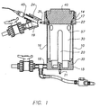
- the apparatus comprises an electrolytic cell 10, formed of electrically non-conductive material such as PVC, and comprising a base 15, sides 16 and an upper portion 17.
- An electrolyte inlet port 18 is provided towards the bottom of the cell and an electrolyte outlet port 19 is provided towards the top of the cell.
- An anode 20 in the form of a platinised titanium rod, is secured to the base of the cell by means of a bolt 21 which acts as an electrical connector for the anode.
- the anode 20 lies along the axis of the cell 10.
- a reference electrode 45 is positioned in a side arm 24 of the cell 10 and protrudes into the outlet port 19 of the cell.
- a suitable reference electrode is a pH sensitive glass electrode such as a YOKOGAWA SM21/AG2 glass electrode.
- the upper part 17 of the cell is in the form of a neck portion having an opening defined by a stainless steel ring 22.
- the contact surface of the ring 22 is frusto-conically shaped, having its narrower radius downwards.
- the stainless steel ring 22 is permanently fixed to one end of a bolt 31 which extends through the wall of the cell and provides a connector for the cathode 30.
- a sealing ring 14 Positioned in the neck of the cell, above the level of the annular ring 22, is a sealing ring 14.
- the apparatus further comprises a lid 40 so shaped as to fit into the neck portion of the cell.
- the lid 40 is formed of electrically non-conductive material such as PVC.
- the lower portion of the lid 40 is shaped to correspond to the shape of the ring 22.
- the cathode 30 has a deformable upper edge portion.
- the sheet material of which the cathode is formed is sufficiently resilient to allow upper edge portion to bend outwardly in response to outwardly directed force.
- the deformable upper edge portion of the cathode lies adjacent the stainless steel ring 22. Tightening of the lid causes the upper edge portion of the cathode 30 to be clamped firmly by the lid against the ring 22, thereby establishing good electrical contact there-between.
- the cathode is provided with a number of openings 57 which extend therethrough.
- the cathode 30 is located in the cell 10 with its bottom edge supported by a cathode support ledge 35 in the cell.
- One of the openings 57 is located in the neighbourhood of the reference electrode 45.
- the sealing ring 14 bears against the outer surface of the lid 40, thereby forming a tight seal.
- Electrolyte liquid is now fed into the cell by way of the inlet port 18, fills the cell and exits by way of the outlet port 19.
- the effect of the sealing ring 14 is to prevent the electrolyte level rising above the level of the outlet port 19, so maintaining an air space above the liquid and preventing contact between the liquid and the surface of the ring 22. The risk of corrosion of the latter is thereby reduced and the opening of the cell is made easier because the air space fulfils a compression-decompression function.
- the anode 20, the cathode 30 and the reference electrode 45 of the electrolytic cell 10 are connected to a control device 41 which controls the application of electrical power to the anode and the cathode.
- the cell 10 is fed with contaminated fixer from a first fixer container 42 via a pump 43 which is provided with a filter (not shown).
- the contaminated fixing solution is topped up from time to time with fresh fixing solution from a second fixer container 44, while the total liquid volume is maintained at a constant level by means of an overflow 46.
- FIG. 3 shows the apparatus for de-silvering silver-containing solutions comprising the electrolytic cell 10, the anode 20, the cathode 30 and the reference electrode 45 positioned adjacent the cathode.
- Electrical power supply control means in the form of the control device 41 is provided for controlling the supply of electrical power to the anode 20 and the cathode 30.
- the control device 41 includes a potentiometer 60 for adjusting the potential difference applied from a power source 62 between the anode 20 and the cathode 30.
- a voltage meter 64 measures the potential difference between the cathode 30 and the reference electrode 45 and a current meter 65 measures the current flow through the cell.
- a start switch 66 initiates the start of a de-silvering process by completing the connection between the power source 62 and the cathode 30.
- a timer 68 measures the time elapsed from the operation of the start switch 66.
- a micro-processor 70 or other suitable control circuit, is linked to the voltage meter 64, the current meter 65 and the timer 68 and is programmed to adjust the potentiometer 60 in response to the timer 68, the voltage meter 64 and the current meter 65.
- the apparatus shown in the Figures is operated as follows.
- the solution to be de-silvered is a (ex Agfa-Gevaert) commercially available photographic fixer G333 having a pH of 5.3 which is loaded with 1 g/l silver. A new cathode is used.
- the start switch 66 is closed.
- the micro-processor 70 sets the control device 41 into its diffusion limitation current density estimating mode.
- the potentiometer 60 is adjusted to apply a predetermined potential of -560 mV to the cathode 30. During this mode the current flowing through the cell, about 2 A, is measured by the current meter 65, which supplies a signal indicative of this diffusion limitation current to the micro-processor 70.
- the micro-processor 70 having been pre-programmed with the predetermined fraction of say 40%, then calculates the required de-silvering current of 800 mA.
- the micro-processor 70 After a period of time of 60 seconds pre-programmed into the micro-processor 70, the latter switches the control device 41 to its de-silvering mode.
- the micro-processor 70 initially adjusts the potentiometer 60 to cause the anode-cathode potential difference to be slowly decreased while continuously monitoring the cell current as measured by the current meter 65.
- the micro-processor 70 monitors the cathode potential of -520 mV as measured by the voltage meter 64 and applies potentiostatic control by adjusting the potentiometer 60 to ensure that the cathode potential remains constant at this target value.
- the micro-processor 70 monitors the cell current as measured by the current meter 65. As soon as this monitored cell current differs from the calculated de-silvering current of 800 mA, the micro-processor 70 makes an appropriate modification to the target potential and adjusts the potentiometer 60 accordingly.
- the micro-processor 70 After a given period of time of 10 minutes pre-programmed into the micro-processor 70, the latter switches the control device 41 to the diffusion limitation current estimating mode again and the sequence is repeated. The quality of silver adhesion to the cathode is good.
- the means for estimating the diffusion limitation current density of the electrolytic cell and for causing silver to be deposited on the cathode at a de-silvering current density which is lower than the diffusion limitation current density may together be constituted by a control circuit which comprises a potentiometer for adjusting the potential difference applied from a power source between the anode and the cathode, a voltage meter which measures the potential difference between the cathode and the reference electrode and a current meter measures the current flow through the cell.
- a micro-processor may be linked to the voltage meter and the current meter and be programmed to adjust the potentiometer as required.
Landscapes
- Chemical & Material Sciences (AREA)
- Engineering & Computer Science (AREA)
- Chemical Kinetics & Catalysis (AREA)
- Electrochemistry (AREA)
- Materials Engineering (AREA)
- Metallurgy (AREA)
- Organic Chemistry (AREA)
- Electrolytic Production Of Metals (AREA)
Description
Claims (36)
- A process for de-silvering a silver-containing solution in an electrolytic cell having an anode and a cathode,
characterised by the following steps:(a) periodically estimating the diffusion limitation current density of said electrolytic cell by measuring a current flow there-through; and(b) adjusting the current density to values lower than said diffusion limited current. - A process according to claim 1, wherein said steps (a) and (b) are performed in respect of the same cathode surface.
- A process according to claim 1 or 2, wherein steps (a) and (b) are performed alternately.
- A process according to any preceding claim, wherein said de-silvering current density is 10% to 90% of said diffusion limitation current density.
- A process according to claim 4, wherein said de-silvering current density is 30% to 80% of said diffusion limitation current density.
- A process according to claim 4 or 5, wherein said de-silvering current is controlled galvanostatically to a substantially stable value.
- A process according to claim 4 or 5, wherein said de-silvering current is controlled potentiostatically.
- A process according to any preceding claim, wherein the time taken for step (a) is from 1 to 25% of the total de-silvering time.
- A process according to claim 8, wherein the time taken for step (a) is from 2% to 10% of the total de-silvering time.
- A process according to claim 3, wherein step (a) is carried out at a frequency sufficiently high that the silver content of said silver-containing solution falls by less than 50% in the immediately preceding step (b).
- A process according to claim 10, wherein step (a) is carried out at a frequency sufficiently high that the silver content of said silver-containing solution falls by less than 20% in the immediately preceding step (b).
- A process according to any preceding claim, wherein step (a) is carried out by potentiostatically setting said cathode to a predetermined cathode potential and measuring the current flow through said electrolytic cell.
- A process according to claim 12, wherein, in step (a) said cathode is set to a potential where no more than 40% of the current at the cathode is consumed by side reactions.
- A process according to claim 13, wherein, in step (a) said cathode is set to a potential where no more than 20% of the current at the cathode is consumed by side reactions.
- A process according to claim 12, wherein step (a) is carried out by potentiostatically setting said cathode to a predetermined cathode potential relative to said anode.
- A process according to claim 12, wherein step (a) is carried out by potentiostatically setting said cathode to a predetermined cathode potential relative to a third electrode, not being said cathode nor said anode.
- A process according to claim 16, wherein said third electrode is a reference electrode.
- A process according to claim 17, wherein said third electrode is a pH sensitive reference electrode.
- A process according to claim 18, wherein said pH sensitive reference electrode is a glass electrode.
- A process according to claim 18, wherein said predetermined cathode potential is from -510 to -590 mV versus said glass electrode.
- A process according to claim 20, wherein said predetermined cathode potential is from -530 to -560 mV versus said glass electrode.
- A process according to claim 12, wherein said predetermined cathode potential is more negative than the de-poisoning potential of the cell.
- A process according to claim 12, wherein prior to step (a) a current surge is applied to said cathode during which the cathode potential is at least 20 mV more negative than said predetermined cathode potential for a period of less than 10 seconds.
- A process according to claim 23, wherein during said current surge the cathode potential is at least 50 mV more negative than said predetermined cathode potential for a period of less than 3 seconds.
- A process according to any preceding claim, wherein, in step (a) said diffusion limitation current density is estimated from the shape of the curve of current density versus potential difference between said anode and said cathode.
- A process according to any preceding claim, wherein, in step (a) said diffusion limitation current density is estimated from the shape of the curve of current density versus potential difference between said cathode and a third electrode.
- A process according to any preceding claim, wherein, in step (a) said diffusion limitation current density is estimated from responses to known potential variations applied between said cathode and said anode.
- A process according to any preceding claim, wherein step (a) is carried out automatically.
- An apparatus for de-silvering a silver-containing solution comprising an electrolytic cell having an anode and a cathode, characterised by:(a) means for estimating the diffusion limitation current density of said electrolytic cell by measuring a current flow there-through; and(b) means for adjusting the current density causing silver to be deposited on said cathode at a de-silvering current density which is lower than said diffusion limitation current density.
- An apparatus according to claim 29, further comprising means for galvanostatically controlling said de-silvering current to a substantially stable value.
- An apparatus according to claim 29, further comprising means for potentiostatically controlling said de-silvering current to a substantially stable value.
- An apparatus according to claim 31, further comprising a third electrode, not being said cathode nor said anode.
- An apparatus according to claim 32, wherein said third electrode is a reference electrode.
- An apparatus according to claim 33, wherein said third electrode is a pH sensitive reference electrode.
- An apparatus according to claim 34, wherein said pH sensitive reference electrode is a glass electrode.
- An apparatus according to any one of claims 29 to 34, further comprising an intelligent control device for automatically estimating the diffusion limitation current density of said electrolytic cell.
Priority Applications (3)
| Application Number | Priority Date | Filing Date | Title |
|---|---|---|---|
| EP19950201953 EP0754780B1 (en) | 1995-07-15 | 1995-07-15 | Process for de-silvering a silver-containing solution |
| DE1995624074 DE69524074T2 (en) | 1995-07-15 | 1995-07-15 | Method and device for desilvering solutions |
| US08/677,197 US5759377A (en) | 1995-07-15 | 1996-07-09 | Process for de-silvering of a silver-containing solution |
Applications Claiming Priority (1)
| Application Number | Priority Date | Filing Date | Title |
|---|---|---|---|
| EP19950201953 EP0754780B1 (en) | 1995-07-15 | 1995-07-15 | Process for de-silvering a silver-containing solution |
Publications (2)
| Publication Number | Publication Date |
|---|---|
| EP0754780A1 EP0754780A1 (en) | 1997-01-22 |
| EP0754780B1 true EP0754780B1 (en) | 2001-11-21 |
Family
ID=8220493
Family Applications (1)
| Application Number | Title | Priority Date | Filing Date |
|---|---|---|---|
| EP19950201953 Expired - Lifetime EP0754780B1 (en) | 1995-07-15 | 1995-07-15 | Process for de-silvering a silver-containing solution |
Country Status (2)
| Country | Link |
|---|---|
| EP (1) | EP0754780B1 (en) |
| DE (1) | DE69524074T2 (en) |
Families Citing this family (3)
| Publication number | Priority date | Publication date | Assignee | Title |
|---|---|---|---|---|
| GB9815168D0 (en) | 1998-07-13 | 1998-09-09 | Eastman Kodak Co | Recovery of metal from solution |
| GB9815167D0 (en) | 1998-07-13 | 1998-09-09 | Eastman Kodak Co | Recovery of metal from solution |
| ITMI20050580A1 (en) * | 2005-04-07 | 2006-10-08 | De Nora Elettrodi Spa | METAL METAL DEFROSTING METHOD |
Family Cites Families (11)
| Publication number | Priority date | Publication date | Assignee | Title |
|---|---|---|---|---|
| FR1357177A (en) | 1963-03-20 | 1964-04-03 | Bayer Ag | Device for recovering silver from fixing baths |
| GB1203757A (en) | 1966-12-08 | 1970-09-03 | Minnesota Mining & Mfg | Heterocyclic compounds |
| GB1209146A (en) | 1966-12-09 | 1970-10-21 | Minnesota Mining & Mfg | Substituted tetraazaindene compounds and their use as stabilizers for photographic silver halide emulsions |
| JPS5231738B2 (en) | 1973-08-13 | 1977-08-17 | ||
| US3875032A (en) * | 1974-01-03 | 1975-04-01 | Foresight Enterprises Inc | Method for controlling a silver-recovery plating system |
| GB1500278A (en) | 1975-07-24 | 1978-02-08 | Kodak Ltd | Photographic silver halide emulsions |
| LU82188A1 (en) * | 1980-02-21 | 1981-09-10 | Esterol Ag | PROCESS AND APPARATUS FOR TREATING PHOTOGRAPHIC FIXER BATHS |
| DE3569623D1 (en) | 1985-02-04 | 1989-05-24 | Agfa Gevaert Nv | Substituted triazolopyrimidines and their use in light-sensitive photographic elements |
| FR2582022B1 (en) | 1985-05-14 | 1988-02-19 | Kodak Pathe | METHOD AND DEVICE FOR REGULATING THE POSITION OF THE OPERATING POINT OF AN ELECTROLYSIS CELL |
| BE1000646A6 (en) * | 1987-06-05 | 1989-02-28 | Univ Bruxelles | Electrochemical characterisation of electrolytes - to produce specific metallographic structures during electrolysis |
| DE69214455T2 (en) | 1992-11-10 | 1997-04-30 | Agfa Gevaert Nv | Use of a pH-sensitive reference electrode for electrolytic desilvering |
-
1995
- 1995-07-15 EP EP19950201953 patent/EP0754780B1/en not_active Expired - Lifetime
- 1995-07-15 DE DE1995624074 patent/DE69524074T2/en not_active Expired - Fee Related
Also Published As
| Publication number | Publication date |
|---|---|
| DE69524074T2 (en) | 2002-07-04 |
| DE69524074D1 (en) | 2002-01-03 |
| EP0754780A1 (en) | 1997-01-22 |
Similar Documents
| Publication | Publication Date | Title |
|---|---|---|
| US5770034A (en) | Process and apparatus for desilvering a silver-containing solution | |
| US5951844A (en) | Process and apparatus for desilvering a silver-containing solution | |
| EP0598144B1 (en) | Use of a pH sensitive reference electrode in electrolytic desilvering | |
| US4324621A (en) | Method and apparatus for controlling the quality of electrolytes | |
| US4287044A (en) | Silver recovery apparatus | |
| JP2000045088A (en) | Recovering method and device of metal from solution | |
| US5759377A (en) | Process for de-silvering of a silver-containing solution | |
| EP0754780A1 (en) | Process for de-silvering a silver-containing solution | |
| US4362608A (en) | Silver recovery method | |
| JP2801670B2 (en) | Method for controlling composition of copper plating bath using insoluble anode | |
| CA1126684A (en) | Bipolar refining of lead | |
| US5454924A (en) | Apparatus for the electrolytic recovery of silver from solutions containing silver | |
| EP0754781A1 (en) | A process and apparatus for desilvering a silver-containing solution | |
| EP0803591B1 (en) | A process and apparatus for desilvering a silver-containing solution | |
| US4443301A (en) | Controlling metal electro-deposition using electrolyte containing two polarizing agents | |
| US4153521A (en) | Method of automatic control and optimization of electrodeposition conditions | |
| EP0930380B1 (en) | Electrolytic cell with removable electrode and its operating method | |
| EP0215643B1 (en) | Method for monitoring the quality of zinc sulfate electrolyte containing antimony (v) | |
| US6187167B1 (en) | Recovery of metal from solution | |
| US5639362A (en) | Apparatus and method for de-silvering a silver-containing solution | |
| CA1155790A (en) | Method and apparatus for controlling the electrodeposition of metals | |
| JPH0331800B2 (en) | ||
| US4104132A (en) | Method for eliminating solution-level attack on cathodes during electrolysis | |
| GB2057139A (en) | Method for Determining Electrolyte Quality in Electrodeposition | |
| JPS6361392B2 (en) |
Legal Events
| Date | Code | Title | Description |
|---|---|---|---|
| PUAI | Public reference made under article 153(3) epc to a published international application that has entered the european phase |
Free format text: ORIGINAL CODE: 0009012 |
|
| AK | Designated contracting states |
Kind code of ref document: A1 Designated state(s): DE FR GB |
|
| 17P | Request for examination filed |
Effective date: 19970722 |
|
| 17Q | First examination report despatched |
Effective date: 19991011 |
|
| GRAG | Despatch of communication of intention to grant |
Free format text: ORIGINAL CODE: EPIDOS AGRA |
|
| GRAG | Despatch of communication of intention to grant |
Free format text: ORIGINAL CODE: EPIDOS AGRA |
|
| GRAH | Despatch of communication of intention to grant a patent |
Free format text: ORIGINAL CODE: EPIDOS IGRA |
|
| GRAH | Despatch of communication of intention to grant a patent |
Free format text: ORIGINAL CODE: EPIDOS IGRA |
|
| GRAA | (expected) grant |
Free format text: ORIGINAL CODE: 0009210 |
|
| AK | Designated contracting states |
Kind code of ref document: B1 Designated state(s): DE FR GB |
|
| PG25 | Lapsed in a contracting state [announced via postgrant information from national office to epo] |
Ref country code: FR Free format text: LAPSE BECAUSE OF FAILURE TO SUBMIT A TRANSLATION OF THE DESCRIPTION OR TO PAY THE FEE WITHIN THE PRESCRIBED TIME-LIMIT Effective date: 20011121 |
|
| REG | Reference to a national code |
Ref country code: GB Ref legal event code: IF02 |
|
| REF | Corresponds to: |
Ref document number: 69524074 Country of ref document: DE Date of ref document: 20020103 |
|
| RAP2 | Party data changed (patent owner data changed or rights of a patent transferred) |
Owner name: AGFA-GEVAERT |
|
| PLBE | No opposition filed within time limit |
Free format text: ORIGINAL CODE: 0009261 |
|
| STAA | Information on the status of an ep patent application or granted ep patent |
Free format text: STATUS: NO OPPOSITION FILED WITHIN TIME LIMIT |
|
| EN | Fr: translation not filed |
Owner name: VOEST-ALPINE SCHIENEN GMBH Effective date: 20020710 |
|
| 26N | No opposition filed |
Opponent name: VOEST-ALPINE SCHIENEN GMBH Effective date: 20020710 |
|
| REG | Reference to a national code |
Ref country code: GB Ref legal event code: 746 Effective date: 20040921 |
|
| PGFP | Annual fee paid to national office [announced via postgrant information from national office to epo] |
Ref country code: GB Payment date: 20060721 Year of fee payment: 12 Ref country code: DE Payment date: 20060721 Year of fee payment: 12 |
|
| REG | Reference to a national code |
Ref country code: GB Ref legal event code: 732E |
|
| GBPC | Gb: european patent ceased through non-payment of renewal fee |
Effective date: 20070715 |
|
| PG25 | Lapsed in a contracting state [announced via postgrant information from national office to epo] |
Ref country code: DE Free format text: LAPSE BECAUSE OF NON-PAYMENT OF DUE FEES Effective date: 20080201 |
|
| PG25 | Lapsed in a contracting state [announced via postgrant information from national office to epo] |
Ref country code: GB Free format text: LAPSE BECAUSE OF NON-PAYMENT OF DUE FEES Effective date: 20070715 |