EP0753786A1 - Optische Strukturen mit zwei optischen Führungspfaden - Google Patents
Optische Strukturen mit zwei optischen Führungspfaden Download PDFInfo
- Publication number
- EP0753786A1 EP0753786A1 EP96304866A EP96304866A EP0753786A1 EP 0753786 A1 EP0753786 A1 EP 0753786A1 EP 96304866 A EP96304866 A EP 96304866A EP 96304866 A EP96304866 A EP 96304866A EP 0753786 A1 EP0753786 A1 EP 0753786A1
- Authority
- EP
- European Patent Office
- Prior art keywords
- wavelength
- optical
- radiation
- core
- guidance paths
- Prior art date
- Legal status (The legal status is an assumption and is not a legal conclusion. Google has not performed a legal analysis and makes no representation as to the accuracy of the status listed.)
- Withdrawn
Links
- 230000003287 optical effect Effects 0.000 title claims abstract description 56
- 230000005855 radiation Effects 0.000 claims abstract description 72
- 230000008878 coupling Effects 0.000 claims abstract description 38
- 238000010168 coupling process Methods 0.000 claims abstract description 38
- 238000005859 coupling reaction Methods 0.000 claims abstract description 38
- 239000002019 doping agent Substances 0.000 claims abstract description 31
- 230000008859 change Effects 0.000 claims abstract description 19
- 239000000835 fiber Substances 0.000 claims description 44
- 239000013307 optical fiber Substances 0.000 claims description 38
- 238000000034 method Methods 0.000 claims description 32
- YBMRDBCBODYGJE-UHFFFAOYSA-N germanium dioxide Chemical group O=[Ge]=O YBMRDBCBODYGJE-UHFFFAOYSA-N 0.000 claims description 30
- 238000004519 manufacturing process Methods 0.000 claims description 12
- 238000005253 cladding Methods 0.000 claims description 6
- 229910052761 rare earth metal Inorganic materials 0.000 claims description 3
- 150000002910 rare earth metals Chemical class 0.000 claims description 3
- 230000003247 decreasing effect Effects 0.000 claims description 2
- VYPSYNLAJGMNEJ-UHFFFAOYSA-N Silicium dioxide Chemical compound O=[Si]=O VYPSYNLAJGMNEJ-UHFFFAOYSA-N 0.000 description 2
- 230000005684 electric field Effects 0.000 description 2
- 239000000463 material Substances 0.000 description 2
- 229910052691 Erbium Inorganic materials 0.000 description 1
- UFHFLCQGNIYNRP-UHFFFAOYSA-N Hydrogen Chemical compound [H][H] UFHFLCQGNIYNRP-UHFFFAOYSA-N 0.000 description 1
- 238000005452 bending Methods 0.000 description 1
- 230000008901 benefit Effects 0.000 description 1
- 230000001186 cumulative effect Effects 0.000 description 1
- UYAHIZSMUZPPFV-UHFFFAOYSA-N erbium Chemical compound [Er] UYAHIZSMUZPPFV-UHFFFAOYSA-N 0.000 description 1
- 238000001914 filtration Methods 0.000 description 1
- 230000004927 fusion Effects 0.000 description 1
- 229910052739 hydrogen Inorganic materials 0.000 description 1
- 239000001257 hydrogen Substances 0.000 description 1
- 238000005259 measurement Methods 0.000 description 1
- 238000012544 monitoring process Methods 0.000 description 1
- 238000004382 potting Methods 0.000 description 1
- 239000000377 silicon dioxide Substances 0.000 description 1
- 239000000758 substrate Substances 0.000 description 1
- 238000009281 ultraviolet germicidal irradiation Methods 0.000 description 1
Images

Classifications
-
- H—ELECTRICITY
- H01—ELECTRIC ELEMENTS
- H01S—DEVICES USING THE PROCESS OF LIGHT AMPLIFICATION BY STIMULATED EMISSION OF RADIATION [LASER] TO AMPLIFY OR GENERATE LIGHT; DEVICES USING STIMULATED EMISSION OF ELECTROMAGNETIC RADIATION IN WAVE RANGES OTHER THAN OPTICAL
- H01S3/00—Lasers, i.e. devices using stimulated emission of electromagnetic radiation in the infrared, visible or ultraviolet wave range
- H01S3/05—Construction or shape of optical resonators; Accommodation of active medium therein; Shape of active medium
- H01S3/06—Construction or shape of active medium
- H01S3/063—Waveguide lasers, i.e. whereby the dimensions of the waveguide are of the order of the light wavelength
- H01S3/067—Fibre lasers
- H01S3/06708—Constructional details of the fibre, e.g. compositions, cross-section, shape or tapering
-
- G—PHYSICS
- G02—OPTICS
- G02F—OPTICAL DEVICES OR ARRANGEMENTS FOR THE CONTROL OF LIGHT BY MODIFICATION OF THE OPTICAL PROPERTIES OF THE MEDIA OF THE ELEMENTS INVOLVED THEREIN; NON-LINEAR OPTICS; FREQUENCY-CHANGING OF LIGHT; OPTICAL LOGIC ELEMENTS; OPTICAL ANALOGUE/DIGITAL CONVERTERS
- G02F1/00—Devices or arrangements for the control of the intensity, colour, phase, polarisation or direction of light arriving from an independent light source, e.g. switching, gating or modulating; Non-linear optics
- G02F1/29—Devices or arrangements for the control of the intensity, colour, phase, polarisation or direction of light arriving from an independent light source, e.g. switching, gating or modulating; Non-linear optics for the control of the position or the direction of light beams, i.e. deflection
- G02F1/31—Digital deflection, i.e. optical switching
- G02F1/313—Digital deflection, i.e. optical switching in an optical waveguide structure
- G02F1/3131—Digital deflection, i.e. optical switching in an optical waveguide structure in optical fibres
-
- H—ELECTRICITY
- H01—ELECTRIC ELEMENTS
- H01S—DEVICES USING THE PROCESS OF LIGHT AMPLIFICATION BY STIMULATED EMISSION OF RADIATION [LASER] TO AMPLIFY OR GENERATE LIGHT; DEVICES USING STIMULATED EMISSION OF ELECTROMAGNETIC RADIATION IN WAVE RANGES OTHER THAN OPTICAL
- H01S2301/00—Functional characteristics
- H01S2301/02—ASE (amplified spontaneous emission), noise; Reduction thereof
-
- H—ELECTRICITY
- H01—ELECTRIC ELEMENTS
- H01S—DEVICES USING THE PROCESS OF LIGHT AMPLIFICATION BY STIMULATED EMISSION OF RADIATION [LASER] TO AMPLIFY OR GENERATE LIGHT; DEVICES USING STIMULATED EMISSION OF ELECTROMAGNETIC RADIATION IN WAVE RANGES OTHER THAN OPTICAL
- H01S3/00—Lasers, i.e. devices using stimulated emission of electromagnetic radiation in the infrared, visible or ultraviolet wave range
- H01S3/05—Construction or shape of optical resonators; Accommodation of active medium therein; Shape of active medium
- H01S3/06—Construction or shape of active medium
- H01S3/063—Waveguide lasers, i.e. whereby the dimensions of the waveguide are of the order of the light wavelength
- H01S3/067—Fibre lasers
- H01S3/06708—Constructional details of the fibre, e.g. compositions, cross-section, shape or tapering
- H01S3/06729—Peculiar transverse fibre profile
-
- H—ELECTRICITY
- H01—ELECTRIC ELEMENTS
- H01S—DEVICES USING THE PROCESS OF LIGHT AMPLIFICATION BY STIMULATED EMISSION OF RADIATION [LASER] TO AMPLIFY OR GENERATE LIGHT; DEVICES USING STIMULATED EMISSION OF ELECTROMAGNETIC RADIATION IN WAVE RANGES OTHER THAN OPTICAL
- H01S3/00—Lasers, i.e. devices using stimulated emission of electromagnetic radiation in the infrared, visible or ultraviolet wave range
- H01S3/09—Processes or apparatus for excitation, e.g. pumping
- H01S3/091—Processes or apparatus for excitation, e.g. pumping using optical pumping
- H01S3/094—Processes or apparatus for excitation, e.g. pumping using optical pumping by coherent light
- H01S3/094003—Processes or apparatus for excitation, e.g. pumping using optical pumping by coherent light the pumped medium being a fibre
Definitions
- This invention relates to optical structures having two optical guidance paths between which coupling occurs in a band about a predetermined wavelength.
- Such structures comprise integrated optics planar devices and optical fibre structures and have many applications, for example in filtering, amplifying and sensing strain and temperature.
- an article by RC Alferness and RV Schmidt on pages 161-163 of Applied Physics Letters 33(2) dated 15 July 1978 discloses a two waveguide integrated optics planar device which functions as a filter
- EP-A-0308114 relates to a two core optical fibre structure which is operable as a filter
- EP-A-0324541 and EP-A-417441 each disclose optical fibre amplifiers which include a two core optical fibre
- EP-A-0250194 discloses a strain and temperature sensing apparatus which includes a two core optical fibre.
- a problem which arises in manufacturing such optical structures is ensuring that coupling between the optical guidance paths occurs in a band about the required predetermined wavelength.
- the known structures are manufactured such that the two guidance paths have respective propagation constants which vary differently with wavelength and coincide at one wavelength and are arranged such that coupling occurs between the guidance paths in a band about that wavelength.
- the propagation constant of each path is a function of parameters of the waveguide or core and the material immediately surrounding the same and in particular the refractive indices thereof. Thus it is difficult to ensure that the wavelength at which the propagation constants coincide is the required coupling wavelength.
- the above-mentioned problem is solved in a way, which can be carried out as part of the manufacturing process and which does not require straining, by changing the propagation constant of at least one of the guidance paths by subjecting it to radiation.
- the present invention provides a method of manufacturing an optical structure having two optical guidance paths between which coupling occurs in a band about one predetermined wavelength: said method comprising providing an optical structure having two optical guidance paths with respective propagation constants which vary differently with wavelength and coincide at one given wavelength arranged such that coupling occurs between said optical guidance paths in a band about said one given wavelength, said structure including a radiation responsive refractive index changing dopant substantially throughout the length of at least one of said guidance paths over at least a region of the cross-section thereof; and subjecting the or at least one of the guidance paths including said dopant to radiation to change the propagation constant thereof until said one given wavelength equals said one predetermined wavelength.
- the method may be carried out such that said one given wavelength is increased to said one predetermined wavelength by said radiation subjecting step.
- the method may be carried out such that said one given wavelength is decreased to said one predetermined wavelength by said radiation subjecting step.
- the radiation is applied in steps to incrementally change said one given wavelength until it equals said one predetermined wavelength.
- the radiation may be launched along the or one of the paths including said dopant.
- the radiation may be used to change the propagation constant of only the path along which it is launched.
- the radiation may be directed transversely at said paths.
- the radiation may be used to change the propagation constant of the or each path which includes said dopant.
- the method is applicable to the manufacture of integrated optics planar devices and to the manufacture of optical fibre structures.
- the optical structure provided comprises an optical fibre structure in which two cores are located within a common cladding to provide said two optical guidance paths, one of said cores being located centrally of said optical fibre and wherein said radiation is launched along said central core.
- said two core fibre structure is spliced to a single core fibre, the single core of which is aligned with the central core of the two core fibre structure and said radiation is launched into said central core via said single core.
- the optical fibre structure may be potted in a substantially mechanically unstressed condition prior to said radiation subjecting step.
- the wavelength of the radiation for the radiation subjecting step is significantly removed from the wavelengths of the lightwaves which the cores of the two core fibre structure are to guide in use of the structure.
- the radiation may have a wavelength substantially below 900 nm or substantially above 1600 nm.
- the radiation may be UV radiation at say 193,244 or 248 nm and in the latter case the radiation may be produced by a CO 2 laser which operates at 10600nm and is preferably directed transversely at the paths.
- UV radiation is advantageously used when the or each core of the fibre structure is doped with germania as a refractive index raising dopant since germania is also a UV radiation responsive refractive index raising dopant.
- The, or at least one of the, guidance paths including said dopant is pretreated to enhance the change in the propagation constant thereof caused by said radiation.
- such a guidance path may be provided with a rare earth dopant to enhance the change in the propagation constant thereof caused by said radiation.
- the invention also includes an optical structure having two optical guidance paths between which coupling occurs in a band about one predetermined wavelength, wherein a radiation responsive refractive index changing dopant is present in said structure substantially throughout the length of at least one of said guidance paths over at least a region of the cross-section thereof, and wherein the or at least one of the guidance paths provided with said dopant has been subjected to radiation to change the propagation constant thereof such that the respective propagation constants of said guidance paths coincide at only said one predetermined wavelength.
- the invention also includes a method of manufacturing a two core optical fibre structure in which coupling between the cores occurs in a band about one predetermined wavelength: said method comprising providing an optical fibre structure in which two cores are located within a common cladding to provide two optical guidance paths with respective propagation constants which vary differently with wavelength and coincide at one given wavelength and such that coupling occurs between said optical guidance paths in a band about said one given wavelength, at least one of said cores being doped with germania; and directing UV light into the or one of the cores doped with germania until said one given wavelength equals said one predetermined wavelength.
- the invention also includes a two core optical fibre structure in which coupling occurs between the cores in- a band about one predetermined wavelength, wherein at least one of the cores is doped with germania and the or at least one of the doped cores has been treated with UV light to change the propagation constant of the optical guidance path associated therewith such that the respective propagation constants of the optical guidance paths associated with the two cores coincide at only said one predetermined wavelength.
- the invention also includes an optical amplifier comprising an optical structure made by a method as defined in the last but fourteen paragraph or as defined in the last but two paragraph, wherein said one predetermined wavelength is substantially equal the wavelength of signal to be amplified and a dopant capable of producing stimulated emission at the wavelength of the signal to be amplified when pumped by a pump signal of a different wavelength is present in one of said guidance paths, and a pump source connected to said one guidance path for launching a pump signal at said different wavelength therealong.
- the invention also includes an optical fibre amplifier comprising a two core optical fibre structure made by a method as defined in the last but two paragraph or as defined in the last but one paragraph, wherein said predetermined wavelength of the signal to be amplified and one of said cores is doped with a dopant capable of producing stimulated emission at the wavelength of the signal to be amplified when pumped by a pump signal at a different wavelength, and a pump source connected to said one core for launching a pump signal at said different wavelength therealong.
- the invention also includes an optical fibre telecommunications line comprising at least one amplifier as defined in the last or the last but one paragraph arranged such that a signal being transmitted along said line is fed into one end of the other guidance path or core and exits the other end thereof.
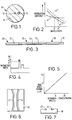
- Figure 1 illustrates an optical fibre structure 10 which comprises two optical cores 12, 14 located within a common cladding 16.
- One core 12 is located centrally of the optical fibre structure 10 and the other core is offset therefrom.
- the cores are uniformly spaced apart throughout the length of the fibre structure 10 and each core 12, 14 provides a respective optical guidance path which extends laterally beyond the core itself and the spacing between the cores is sufficiently small that their optical guidance paths will overlap to permit coupling.
- the material, diameter and refractive index of each core is selected such that the two optical guidance paths provided by the cores have propagation constants which vary differently with wavelength and coincide at one given wavelength.
- the solid lines 12', 14' represent the propagation constants for the two guidance paths provided by the cores 12, 14 of fibre structure as drawn from a preform.
- the propagation constants coincide at wavelength ⁇ '. It is at this wavelength and at wavelengths immediately adjacent thereto that light couples between the guidance paths.
- the width of the passband around ⁇ ' at which light couples between the guidance paths depends inter alia on the extent to which the propagation constants depart from each other to each side of ⁇ '.
- the cores are silica doped throughout their lengths at least over a region thereof with germania as a refractive index raiser dopant. Due to the presence of germania permanent changes to the refractive indices, and thereby the propagation constants, of the cores can be made by subjecting the fibre structure to UV radiation. Thus germania in the cores is a radiation responsive refractive index changing dopant as well as a refractive index raiser dopant.
- the wavelength at which the propagation constants coincide can be modified.
- the propagation constants of the guidance paths provided by both cores can be changed until the wavelength at which the propagation constants coincide is the required coupling wavelength for the application to which the fibre structure is to be put by launching radiation along the paths provided by each core at the same or different cumulative intensities or by directing the radiation transversely of the paths.
- the propagation constant of only one of the guidance paths is changed, and preferably this path is the path provided by the central core.
- the central core is preferred since a radiation may be launched into it via a conventional single core fibre tail fusion spliced to the two core fibre structure with its single core which is central of the tail aligned with the central core of the two core fibre.
- a conventional single core fibre tail fusion spliced to the two core fibre structure with its single core which is central of the tail aligned with the central core of the two core fibre is preferred since a radiation may be launched into it via a conventional single core fibre tail fusion spliced to the two core fibre structure with its single core which is central of the tail aligned with the central core of the two core fibre.
- an input single core fibre tail 20 is spliced to one end of the two core fibre structure 10 with its core 22 aligned with the central core 12 of the two core fibre structure 10.
- an output single core fibre tail 30 is spliced to the other end of the two core fibre structure 10 with its core 32 aligned with the central core 12 of the fibre structure 10.
- UV irradiation of the central core 12 increases its refractive index and causes the propagation constant to increase for each value of wavelength.
- the propagation constant of the guidance path provided by the central core shifts to a position such as that indicated by dotted line 12'' in Figure 2 and the wavelength at which the propagation constants of the two paths coincide increases from ⁇ ' to ⁇ ".
- the two core fibre structure as drawn from its preform has two optical guidance paths which coincide at a wavelength which is less rather than more than the required coupling wavelength, so that tuning can be carried out by launching UV radiation into the central core.
- tuning can be carried out instead by launching irradiation into the offset core. Fine adjustments to the tuning of the coupling wavelength and also the extent of the passband are possible by subjecting both guidance paths to radiation. It will be understood that the output tail is provided to enable monitoring of the radiation step to ensure that the whole of the length of the two core optical fibre is subjected to radiation.
- the fibre may be pretreated with hydrogen to enhance the increase in refractive index caused by the UV radiation.
- the core or cores which are to be subject to UV radiation may include a rare earth dopant which enhances the increase in refractive index caused by that radiation.
- the fibre structure is potted in a substantially mechanically unstressed condition for maintaining its mechanical and thermal stability.
- the coupling characteristics are measured to check that the coupling wavelength is less than that required, and a pulse of high intensity UV light, for example 30 mW, is launched into central core 12 via the input tail 20 and detected at exit from the output tail 30.
- the coupling characteristics of the fibre structure 10 are remeasured and if the coupling wavelength is still less than that required the above procedure is repeated.
- the UV radiation is applied in steps to incrementally increase the coupling wavelength until it equals the required wavelength.
- the above described method increases the refractive index of the central core 12 (from n' before irradiation to n" thereafter) and also increases the propagation constant for the guidance path provided by the central core 12 at each wavelength thus shifting the coupling wavelength from ⁇ ' to ⁇ ".
- the fibre structure may be connected to new tails which would enable the offset core 14 to be subjected to UV radiation and radiation applied to the offset core in steps to incrementally decrease the coupling wavelength until it equals the required coupling wavelength.
- Figure 5 indicates the relationship between germania concentration and the increase in refractive index possible using UV radiation as described above.
- the maximum index change induced by UV radiation in a 10 mole % germania doped core having an initial refractive index of 1.4635 is 0.0003.
- radiation at other wavelengths may be used to change the propagation of the or each core.
- radiation produced by a CO 2 laser may be used.
- a CO 2 laser operates at 10600 nm which is substantially above the operating wavelengths at which known two core fibre structures are utilised.
- UV radiation which is typically produced by known sources at 193, 244 and 248 nm is substantially below such wavelengths.
- the cores of the two core fibre structure must be such that the refractive index raising affect described above does not occur at normal operating powers and wavelengths but instead should occur at powers and wavelengths removed therefrom.
- these wavelengths may be taken to be substantially below 900 nm and substantially above 1600 nm.
- One such device 40 is schematically illustrated in Figures 6 and 7 and comprises two single mode strip optical waveguides 42, 44 provided on a substrate 46.
- the waveguides provide two optical paths with respective propagation constants which vary differently with wavelength and coincide at one given wavelength.
- the waveguides include central portions which are closely adjacent such that coupling at that given wavelength occurs.
- At least one of the guidance paths includes a radiation responsive refractive index changing dopant and accordingly the propagation constant of the or at least one of the guidance paths including this dopant can be changed by the application of radiation in order to change the wavelength at which the propagation constants coincide to a required wavelength.
- FIG. 8 there is schematically illustrated an optical fibre telecommunications line 100 extending between a transmitter 110 and a receiver 120.
- the line includes a plurality of optical fibre amplifiers, two of which are illustrated at 130 and 130A.
- Each optical fibre amplifier comprises a two core optical fibre structure 132 which has been made in accordance with the above-described method.
- the predetermined wavelength at which coupling between the two cores 134 and 136 of the optical fibre 132 occurs is tuned by the above-described method so that it is equal to or substantially equal to the wavelength of the signal which is transmitted in the line 130.
- the core 136 is doped with a dopant capable of producing stimulated emission in a band including the wavelength of the signal which is being transmitted when pumped by a pump signal at a different wavelength.
- the core 136 is doped with erbium which produces stimulated emission at wavelengths between 1530 and 1550 nm when pumped at 980 nm.
- a pump source 138 is connected to one end of the core 136 to launch the pump signal along that core.
- the amplifiers in Figure 8 are pumped such that the pump signals and signals which are being transmitted co-propagate.
- the pump source may be connected to the core 136 so that the pump signal and the signal being transmitted counter-propagate.
- the core 136 could have pump sources connected to both of its ends.
- the signal in the band 1530-1550 nm being transmitted from the transmitter 110 towards the receiver 120 travels along an optical fibre 140 until after a considerable distance it is necessary to amplify the signal in view of its attenuation.
- the optical fibre 140 is spliced to the two core fibre 132 such that its single core 142 is connected to the core 134 of the two-core fibre of the amplifier 130.
- the signal transfers repeatedly between the cores and is amplified when in the core 136 which is pumped at 980 nm by the pump source 138.
- the amplified signal exits the amplifier 130 and is transmitted along optical fibre 142, whose single core 144 is spliced to core 134, towards the next amplifier 130A.
Landscapes
- Physics & Mathematics (AREA)
- Nonlinear Science (AREA)
- Optics & Photonics (AREA)
- Electromagnetism (AREA)
- General Physics & Mathematics (AREA)
- Engineering & Computer Science (AREA)
- Plasma & Fusion (AREA)
- Lasers (AREA)
- Optical Integrated Circuits (AREA)
- Optical Couplings Of Light Guides (AREA)
Applications Claiming Priority (2)
| Application Number | Priority Date | Filing Date | Title |
|---|---|---|---|
| GB9513582A GB2302957B (en) | 1995-07-04 | 1995-07-04 | Optical structures with two optical guidance paths |
| GB9513582 | 1995-07-04 |
Publications (1)
| Publication Number | Publication Date |
|---|---|
| EP0753786A1 true EP0753786A1 (de) | 1997-01-15 |
Family
ID=10777099
Family Applications (1)
| Application Number | Title | Priority Date | Filing Date |
|---|---|---|---|
| EP96304866A Withdrawn EP0753786A1 (de) | 1995-07-04 | 1996-07-01 | Optische Strukturen mit zwei optischen Führungspfaden |
Country Status (6)
| Country | Link |
|---|---|
| US (1) | US5701378A (de) |
| EP (1) | EP0753786A1 (de) |
| AU (1) | AU706296B2 (de) |
| CA (1) | CA2180407C (de) |
| GB (1) | GB2302957B (de) |
| NZ (1) | NZ286926A (de) |
Families Citing this family (3)
| Publication number | Priority date | Publication date | Assignee | Title |
|---|---|---|---|---|
| AUPN526895A0 (en) * | 1995-09-07 | 1995-09-28 | Unisearch Limited | Improvements in control of refractive index |
| GB2340956A (en) * | 1998-08-22 | 2000-03-01 | Marconi Gec Ltd | Controlling the propagation time of an optical delay line using radiation |
| EP2885927B1 (de) | 2012-08-20 | 2018-06-13 | Better Hearing S.A.A.K. Technologies Ltd | Hörhilfegerät |
Citations (7)
| Publication number | Priority date | Publication date | Assignee | Title |
|---|---|---|---|---|
| EP0037793A2 (de) * | 1980-03-31 | 1981-10-14 | Polaroid Corporation | optisches nachrichtenübertragungssystem |
| EP0308114A2 (de) * | 1987-09-17 | 1989-03-22 | PIRELLI GENERAL plc | Struktur mit optischen Fasern |
| EP0324541A2 (de) * | 1988-01-12 | 1989-07-19 | PIRELLI GENERAL plc | Verstärkung optischer Signale |
| EP0417441A1 (de) * | 1989-08-11 | 1991-03-20 | PIRELLI CAVI S.p.A. | Doppelkern-Glasfaser als optischer Breitband-Signal-Verstärker |
| EP0442518A2 (de) * | 1990-02-16 | 1991-08-21 | Sumitomo Electric Industries, Ltd. | Verfahren zum optischen Schalten und optische Schaltvorrichtung |
| WO1993001518A2 (en) * | 1991-07-09 | 1993-01-21 | British Telecommunications Public Limited Company | An optical switch |
| JPH05164927A (ja) * | 1991-12-16 | 1993-06-29 | Hitachi Cable Ltd | 導波路型方向性結合器及びその製造方法 |
Family Cites Families (4)
| Publication number | Priority date | Publication date | Assignee | Title |
|---|---|---|---|---|
| US4546476A (en) * | 1982-12-10 | 1985-10-08 | The Board Of Trustees Of The Leland Stanford Junior University | Fiber optic amplifier |
| US4748687A (en) * | 1984-09-25 | 1988-05-31 | Siemens Aktiengesellschaft | Narrow band laser transmitter |
| US4778238A (en) * | 1985-08-01 | 1988-10-18 | Hicks John W | Optical communications systems and process for signal amplification using stimulated brillouin scattering (SBS) and laser utilized in the system |
| US5295211A (en) * | 1993-01-07 | 1994-03-15 | Corning Incorporated | Fiber amplifier coupler |
-
1995
- 1995-07-04 GB GB9513582A patent/GB2302957B/en not_active Expired - Fee Related
-
1996
- 1996-06-28 US US08/671,650 patent/US5701378A/en not_active Expired - Fee Related
- 1996-07-01 EP EP96304866A patent/EP0753786A1/de not_active Withdrawn
- 1996-07-02 NZ NZ286926A patent/NZ286926A/en unknown
- 1996-07-02 AU AU58312/96A patent/AU706296B2/en not_active Ceased
- 1996-07-03 CA CA002180407A patent/CA2180407C/en not_active Expired - Fee Related
Patent Citations (7)
| Publication number | Priority date | Publication date | Assignee | Title |
|---|---|---|---|---|
| EP0037793A2 (de) * | 1980-03-31 | 1981-10-14 | Polaroid Corporation | optisches nachrichtenübertragungssystem |
| EP0308114A2 (de) * | 1987-09-17 | 1989-03-22 | PIRELLI GENERAL plc | Struktur mit optischen Fasern |
| EP0324541A2 (de) * | 1988-01-12 | 1989-07-19 | PIRELLI GENERAL plc | Verstärkung optischer Signale |
| EP0417441A1 (de) * | 1989-08-11 | 1991-03-20 | PIRELLI CAVI S.p.A. | Doppelkern-Glasfaser als optischer Breitband-Signal-Verstärker |
| EP0442518A2 (de) * | 1990-02-16 | 1991-08-21 | Sumitomo Electric Industries, Ltd. | Verfahren zum optischen Schalten und optische Schaltvorrichtung |
| WO1993001518A2 (en) * | 1991-07-09 | 1993-01-21 | British Telecommunications Public Limited Company | An optical switch |
| JPH05164927A (ja) * | 1991-12-16 | 1993-06-29 | Hitachi Cable Ltd | 導波路型方向性結合器及びその製造方法 |
Non-Patent Citations (2)
| Title |
|---|
| PATENT ABSTRACTS OF JAPAN vol. 017, no. 566 (P - 1629) 14 October 1993 (1993-10-14) * |
| SAIFI M A ET AL: "SENSITIVITY OF TWO CORE FIBER COUPLING TO LIGHT-INDUCED DEFECTS", IEEE PHOTONICS TECHNOLOGY LETTERS, vol. 1, no. 11, 1 November 1989 (1989-11-01), pages 386 - 388, XP000081614 * |
Also Published As
| Publication number | Publication date |
|---|---|
| CA2180407A1 (en) | 1997-01-05 |
| NZ286926A (en) | 1997-11-24 |
| GB2302957B (en) | 1999-07-21 |
| GB2302957A (en) | 1997-02-05 |
| GB9513582D0 (en) | 1995-09-06 |
| CA2180407C (en) | 2002-09-03 |
| AU706296B2 (en) | 1999-06-10 |
| US5701378A (en) | 1997-12-23 |
| AU5831296A (en) | 1997-01-16 |
Similar Documents
| Publication | Publication Date | Title |
|---|---|---|
| US5757540A (en) | Long-period fiber grating devices packaged for temperature stability | |
| EP0675611B1 (de) | Optische Systeme und Vorrichtungen mit Spektrumformungsanordnungen mit langer Periode | |
| US6289699B1 (en) | Wavelength selective optical couplers | |
| KR100277163B1 (ko) | 광섬유 증폭기 구조물 및 이러한 구조물을 사용하는 광신호 필터링 방법 | |
| EP0793123B1 (de) | Einrichtung zur optischen Signalformung für Anwendungen bei komplexen Spektral-formen | |
| US6822786B2 (en) | All fiber gain flattening optical filter | |
| EP0938172B1 (de) | Vorrichtung mit einem verbesserten kaskadiertem Ramanfaserlaser | |
| US5337382A (en) | Article comprising an optical waveguide with in-line refractive index grating | |
| US5740292A (en) | Mode coupling optical waveguide grating | |
| US5216728A (en) | Optical fiber amplifier with filter | |
| KR20010014256A (ko) | 단일 모드 광섬유 | |
| EP0324541A2 (de) | Verstärkung optischer Signale | |
| US6392789B1 (en) | Erbium-doped optical fiber having gratings formed therein and fabrication method thereof | |
| Wang et al. | Tunable CW bi-doped fiber laser system from 1320 to 1370 nm using a fiber Bragg grating | |
| EP0840146B1 (de) | Verfahren zur Herstellung von Faser-Gittern mit grossen Perioden | |
| US5701378A (en) | Optical structures with two optical guidance paths | |
| EP0189196A2 (de) | Ramanverstärktes Filterabzweigungssystem | |
| US6707966B1 (en) | Twisted long-period fiber grating and method for reducing polarization dependent loss and shifting wavelength of a long-perion fiber grating | |
| US6289154B1 (en) | Grating-type optical component and method of manufacturing the same | |
| Chou et al. | Gain flattening filter of an erbium-doped fiber amplifier based on etching long-period gratings technology | |
| Belov et al. | Gain spectrum flattening of erbium-doped fiber amplifier using tapered fiber filter | |
| AU748401B2 (en) | Ultra-broadband low-noise gain-flattened rare-earth-doped fibre amplifier | |
| EP1220383A1 (de) | Verfahren und Vorrichtung zum optischem Pumpen bei optischen Verstärkern | |
| Humbert et al. | Fabrication of long period grating using electric discharge in non-hydrogenated fiber | |
| JP2001024261A (ja) | 波長可変利得等化器及びをそれを用いた光増幅器 |
Legal Events
| Date | Code | Title | Description |
|---|---|---|---|
| PUAI | Public reference made under article 153(3) epc to a published international application that has entered the european phase |
Free format text: ORIGINAL CODE: 0009012 |
|
| AK | Designated contracting states |
Kind code of ref document: A1 Designated state(s): DE ES FR GB IT |
|
| 17P | Request for examination filed |
Effective date: 19970225 |
|
| GRAG | Despatch of communication of intention to grant |
Free format text: ORIGINAL CODE: EPIDOS AGRA |
|
| 17Q | First examination report despatched |
Effective date: 20010323 |
|
| GRAG | Despatch of communication of intention to grant |
Free format text: ORIGINAL CODE: EPIDOS AGRA |
|
| GRAG | Despatch of communication of intention to grant |
Free format text: ORIGINAL CODE: EPIDOS AGRA |
|
| GRAH | Despatch of communication of intention to grant a patent |
Free format text: ORIGINAL CODE: EPIDOS IGRA |
|
| STAA | Information on the status of an ep patent application or granted ep patent |
Free format text: STATUS: THE APPLICATION IS DEEMED TO BE WITHDRAWN |
|
| 18D | Application deemed to be withdrawn |
Effective date: 20020716 |