EP0753722A2 - Monitoring system for liquid level control - Google Patents
Monitoring system for liquid level control Download PDFInfo
- Publication number
- EP0753722A2 EP0753722A2 EP96304999A EP96304999A EP0753722A2 EP 0753722 A2 EP0753722 A2 EP 0753722A2 EP 96304999 A EP96304999 A EP 96304999A EP 96304999 A EP96304999 A EP 96304999A EP 0753722 A2 EP0753722 A2 EP 0753722A2
- Authority
- EP
- European Patent Office
- Prior art keywords
- radiation
- panel
- level
- oil
- detector
- Prior art date
- Legal status (The legal status is an assumption and is not a legal conclusion. Google has not performed a legal analysis and makes no representation as to the accuracy of the status listed.)
- Withdrawn
Links
Images

Classifications
-
- F—MECHANICAL ENGINEERING; LIGHTING; HEATING; WEAPONS; BLASTING
- F25—REFRIGERATION OR COOLING; COMBINED HEATING AND REFRIGERATION SYSTEMS; HEAT PUMP SYSTEMS; MANUFACTURE OR STORAGE OF ICE; LIQUEFACTION SOLIDIFICATION OF GASES
- F25B—REFRIGERATION MACHINES, PLANTS OR SYSTEMS; COMBINED HEATING AND REFRIGERATION SYSTEMS; HEAT PUMP SYSTEMS
- F25B31/00—Compressor arrangements
- F25B31/002—Lubrication
-
- G—PHYSICS
- G01—MEASURING; TESTING
- G01F—MEASURING VOLUME, VOLUME FLOW, MASS FLOW OR LIQUID LEVEL; METERING BY VOLUME
- G01F23/00—Indicating or measuring liquid level or level of fluent solid material, e.g. indicating in terms of volume or indicating by means of an alarm
- G01F23/22—Indicating or measuring liquid level or level of fluent solid material, e.g. indicating in terms of volume or indicating by means of an alarm by measuring physical variables, other than linear dimensions, pressure or weight, dependent on the level to be measured, e.g. by difference of heat transfer of steam or water
- G01F23/28—Indicating or measuring liquid level or level of fluent solid material, e.g. indicating in terms of volume or indicating by means of an alarm by measuring physical variables, other than linear dimensions, pressure or weight, dependent on the level to be measured, e.g. by difference of heat transfer of steam or water by measuring the variations of parameters of electromagnetic or acoustic waves applied directly to the liquid or fluent solid material
- G01F23/284—Electromagnetic waves
- G01F23/292—Light, e.g. infrared or ultraviolet
- G01F23/2921—Light, e.g. infrared or ultraviolet for discrete levels
-
- G—PHYSICS
- G01—MEASURING; TESTING
- G01F—MEASURING VOLUME, VOLUME FLOW, MASS FLOW OR LIQUID LEVEL; METERING BY VOLUME
- G01F23/00—Indicating or measuring liquid level or level of fluent solid material, e.g. indicating in terms of volume or indicating by means of an alarm
- G01F23/22—Indicating or measuring liquid level or level of fluent solid material, e.g. indicating in terms of volume or indicating by means of an alarm by measuring physical variables, other than linear dimensions, pressure or weight, dependent on the level to be measured, e.g. by difference of heat transfer of steam or water
- G01F23/28—Indicating or measuring liquid level or level of fluent solid material, e.g. indicating in terms of volume or indicating by means of an alarm by measuring physical variables, other than linear dimensions, pressure or weight, dependent on the level to be measured, e.g. by difference of heat transfer of steam or water by measuring the variations of parameters of electromagnetic or acoustic waves applied directly to the liquid or fluent solid material
- G01F23/284—Electromagnetic waves
- G01F23/292—Light, e.g. infrared or ultraviolet
- G01F23/2921—Light, e.g. infrared or ultraviolet for discrete levels
- G01F23/2922—Light, e.g. infrared or ultraviolet for discrete levels with light-conducting sensing elements, e.g. prisms
- G01F23/2925—Light, e.g. infrared or ultraviolet for discrete levels with light-conducting sensing elements, e.g. prisms using electrical detecting means
- G01F23/2927—Light, e.g. infrared or ultraviolet for discrete levels with light-conducting sensing elements, e.g. prisms using electrical detecting means for several discrete levels, e.g. with more than one light-conducting sensing element
-
- F—MECHANICAL ENGINEERING; LIGHTING; HEATING; WEAPONS; BLASTING
- F25—REFRIGERATION OR COOLING; COMBINED HEATING AND REFRIGERATION SYSTEMS; HEAT PUMP SYSTEMS; MANUFACTURE OR STORAGE OF ICE; LIQUEFACTION SOLIDIFICATION OF GASES
- F25B—REFRIGERATION MACHINES, PLANTS OR SYSTEMS; COMBINED HEATING AND REFRIGERATION SYSTEMS; HEAT PUMP SYSTEMS
- F25B2400/00—Component parts or details not otherwise provided for in this subclass
- F25B2400/07—Details of compressors or related parts
- F25B2400/075—Details of compressors or related parts with parallel compressors
-
- F—MECHANICAL ENGINEERING; LIGHTING; HEATING; WEAPONS; BLASTING
- F25—REFRIGERATION OR COOLING; COMBINED HEATING AND REFRIGERATION SYSTEMS; HEAT PUMP SYSTEMS; MANUFACTURE OR STORAGE OF ICE; LIQUEFACTION SOLIDIFICATION OF GASES
- F25B—REFRIGERATION MACHINES, PLANTS OR SYSTEMS; COMBINED HEATING AND REFRIGERATION SYSTEMS; HEAT PUMP SYSTEMS
- F25B2700/00—Sensing or detecting of parameters; Sensors therefor
- F25B2700/03—Oil level
Definitions
- the invention is concerned with improvements in or relating to a monitoring and control system for maintaining liquid levels in a liquid-containing system.
- the invention therefore provides in one of its several aspects, a monitoring system for use in monitoring a liquid level in a unit, said unit having a casing provided with a radiation-transparent panel, means for emitting radiation in a beam passing from the exterior of the casing through the panel and radiation detecting means for detecting and indicating either the presence or at least substantial absence of a return beam of said radiation reflected from a rear surface of said panel.
- said panel may comprise a sight glass.
- said radiation emitting means may be a source of infra-red or visible light.
- said means for detecting a reflected beam of said radiation may be a photo-transistor device mounted adjacent said radiation emitting device on converging optical axes.
- an infra-red light emitting diode is arranged to pass a beam through the sight glass of a compressor casing.
- the beam of light is reflected from the inner surface of the sight glass back to the photo-transistor device which registers the presence of the reflected beam.
- the light beam passes into and through the oil, very little reflection taking place back to the photo-transistor device.
- the reflection detecting means may have an optimum reflection detecting range approximately equal to the thickness of the glass or similar material in the sight glass panel.
- the presence of a reflected beam is registered and a signal produced and transmitted to an oil control valve.
- a non-actuating condition or "dead-band" is defined in an appropriate switching circuit to prevent unnecessarily frequent operation of the valve, which may be a solenoid valve.
- the reflection detecting means may comprise optical sensor devices at more than one level.
- a timer device may be provided together with an alarm device operable after a pre-determined period of time during which the oil-level is registered as being lower than required.
- a monitoring system for controlling the level of a liquid within a chamber defined by a casing, the system comprising a valve through which liquid is supplied to the chamber, a radiation-transparent panel or panels provided in the casing, at least one radiation source/detector arrangement arranged to direct a beam of radiation onto a pre-determined region of the panel or one of the panels and to detect reflected radiation, the amount of radiation reflected by the or each panel being dependent upon whether or not liquid is present in contact with a rear surface of the panel, and control means for receiving the outputs from the detector, said control means being arranged to open the valve only when the detector outputs correspond to a liquid level below the region and to close the valve only when the detector outputs correspond to a liquid level above the region.
- first and second radiation source/detector arrangements adapted to emit respective beams of radiation onto regions of said panel(s) which are vertically spaced apart in horizontal planes passing through the panel(s) and to detect reflected radiation
- said control means being arranged to receive the outputs from said first and said second source/detector arrangements and to open the valve only when the detector outputs correspond to a liquid level below the lower one of said vertically spaced regions and to close the valve only when the detector outputs correspond to a liquid level above the upper one of said regions.
- Various arrangements which may be found suitable include providing one radiation source/detector arrangement disposed on a first panel and a further radiation source/detector arrangement disposed on a second panel provided at a lower level in the casing, or providing both arrangements in the same panel.
- Figure 1 shows a portion of a refrigeration circuit comprising evaporator and condenser means forming no part of this invention, together with a bank of compressors 2 receiving circulating refrigerant vapour from an evaporator arrangement through lines 4 and providing high pressure vapour to a condenser arrangement through branch lines 6 off line 8.
- Line 8 passes through a separator 10 from which lubricant (oil L) is separated and returned to the compressors 2 via a line 12 to a manifold device 14 adapted to control an array of solenoid valves 16, each adapted to operate to maintain an adequate supply of oil to a desired operating level in a respective compressor 2.
- each compressor is provided with a radiation trans- parent panel 18 in the form of a sight glass.
- the panel is of plain glass and is transparent to infra-red light.
- a source of infra-red light projects a beam 22 into the sight glass 18 where it is incident on the rear surface 24 of the glass at a "valve trigger" level 26.
- An optical sensor 28 which is arranged side-by-side with the source 20, and has an operating axis which converges with that of the source within the thickness of the glass 18 so as to receive a beam of light 22' reflected from the sight glass.
- the source 20 and the sensor 28 are shown as spaced apart vertically. However, it will be understood that an alternative arrangement may be one in which the source 20 and sensor 28 lie in the same horizontal plane, or spaced from one another both vertically and horizontally.
- the lightbeam when oil is present within the compressor casing up to the valve trigger level 26, the lightbeam encounters a glass-oil interface where the refractive index changes from a low value in the glass to a high value in the oil. The major fraction of the light beam thus passes through the interface into the oil with only a relatively small fraction being reflected back through the sight glass.
- the light beam passes through the sight glass and encounters a glass-air interface, i.e. a change from a high refractive index medium to a low refractive index medium.
- the beam 22 is reflected by the rear surface 24 of the glass 18 and is detected by the optical sensor 28.
- the sensor 28 is then activated to produce a signal so that the respective solenoid valve 16 may be caused to open and to supply additional oil to the compressor 2 until the oil level rises above the valve trigger level 26 at which the absence of a beam 22' at the sensor 28 is established.
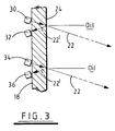
- the system comprises an upper infra-red light source/sensor arrangement 30,32, similar to that described above with reference to Figure 2, to detect when the oil level rises above, or falls below, an upper 'oil' level and a further lower infra-red light source/sensor arrangement 34,36 to detect when the oil level falls below, or rises above, a lower 'no oil' level.
- the two arrangements are spaced apart in the present example so that the distance between the 'oil' and the 'no oil' level is approximately 7mm.
- Control circuitry C monitors the output signals from the two optical sensors 32,36. As the oil level falls from an initial high level, the output from the upper sensor 32 first changes from low to high whilst that from the lower sensor 36 remains low. In this state the solenoid valve 16 is maintained closed by the control circuitry. Only when the output from the lower sensor 36 also changes from low to high, indicating that the oil level has fallen below the 'no oil' level, does the control circuitry open the solenoid value 16, causing the chamber to begin filling with oil. As the oil level rises, the output from the lower sensor 36 first changes from high to low, followed by the output from the upper sensor 32.
- control circuitry Only when the outputs from both sensors 32,36 have changed from high to low does the control circuitry close the solenoid value 16, cutting off the supply of oil to the chamber.
- the control circuitry therefore introduces a hysteresis loop into the switching of the solenoid valve 16 which prevents small fluctuations of the oil level giving rise to solenoid chatter.
- a pressure pad (not shown) is provided in association with the unit which, if the unit becomes dislodged, is arranged to send a signal to the compressor to stop its operation so as to prevent the risk of serious damage thereto.
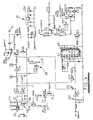
- Figure 4 shows in detail control circuitry for use with the system of Figure 3, where the panel 18, through which light may be reflected from the sources 30, 34 to the detectors 32, 36, is omitted for the sake of clarity.
- the outputs provided by the sensors 32,36 are supplied by way of respective filter capacitors and inverting schmitt triggers IC1a, IC1d, which act to sharpen the switching signals generated by the detectors, to a common summing junction A which provides the input to a further schmitt trigger IC1e.
- the outputs of the schmitt triggers IC1a,IC1d are low (0v) when the sensors 32,34 receive no reflected light and are high (6v) when the contrary is true.
- the third schmitt trigger IC1e is arranged, when the voltage at A is increasing, to provide a high output when that voltage rises above 9v and, when the voltage at A is falling, to provide a low output when that voltage falls below 3v thus providing a dead band of 6v such that a change in the output of only one of the schmitt triggers IC1a, IC1d will not produce a change in the output of schmitt trigger IC1e.
- the output from schmitt trigger IC1e is coupled to the base of a pnp transistor Q1 which has its collector coupled to a pair of light emitting diodes. A first of these diodes provides a visual indicator whilst the second forms part of an optically isolated switch S1 which controls the power supply to the solenoid valve 16.
- the output from the schmitt trigger IC1e is high, indicating that the oil level is above the 'no oil' level, the transistor Q1 remains off, as does the optically isolated switch S1.
- the solenoid valve 16 is in turn closed and no oil is supplied to the compressor 2.
- the output from the schmitt trigger IC1e goes low, turning on the transistor Q1 and the optically isolated switch S1 and opening the solenoid valve 16.
- the solenoid valve is maintained in the open state until such time as the oil level rises above both the 'no oil' and 'oil' levels and the output from the schmitt trigger goes low.
- the outputs from the schmitt triggers IC1a and IC1d are provided to respective 'oil high' and 'oil low' yellow indicator diodes.
- a first of the diodes is on only when the oil level is above the 'oil' level whilst the second diode is on only when the level falls below the 'no oil' level. When the oil level is in the deadband between these two levels, neither diode is on.
- a 'COMPRUN' signal indicative of the state of the compressor, is supplied to a schmitt trigger IC1e after rectification.
- the COMPRUN signal is low, indicating that the compressor is off, the output from the schmitt trigger IC1c is high, acting through a diode D1 to hold the transistor Q1 in an off state and thus holding the solenoid value 16 closed.
- the COMPRUN signal is high, indicating that the compressor is running, the output from schmitt trigger IC1c is low, allowing the transistor Q1 to be controlled by the output from schmitt trigger IC1e.
- a further circuit portion indicated generally by reference numeral 38 is arranged, when the system is being commissioned and power is first applied to the circuit, to temporarily force the output of the schmitt trigger IC1e low, turning on the solenoid valve 16 and thus preventing the oil level from possibly sticking between the 'oil' and the 'no oil' levels.
- the control circuitry is provided with a timer IC2 which receives at its start/stop input the output from a schmitt trigger IC1b which in turn receives as its input the output from schmitt trigger IC1d, coupled to the 'no oil' detector.
- the output from the timer IC2 is supplied via a transistor Q2 and a relay RL1 to an optically isolated switch S2.
- the switch S2 controls the supply of power to the compressor 2.
- the output from the timer causes the switch S2 to couple power to the compressor.
- the timer commences counting. If the timer is allowed to run for four minutes without receiving a stop input from the schmitt trigger IC1d (i.e.
- the timer output is toggled and the switch S2 shuts off power to the compressor, thus preventing the compressor from running for a prolonged period without sufficient oil.
- the timer output is also coupled to green and red LEDS which provide a visual indication of whether or not the compressor is running.
- Schmitt trigger IC1c is also arranged to over-ride the start/stop signal provided to the timer IC2 by the schmitt trigger IC1d when the compressor is not running and the COMPRUN signal is low, so as to maintain the timer in the stop state.
- the circuit indicated generally by reference numeral 40 in Figure 4 illustrates the power supply for the control circuitry.
Landscapes
- Physics & Mathematics (AREA)
- Electromagnetism (AREA)
- Thermal Sciences (AREA)
- Fluid Mechanics (AREA)
- General Physics & Mathematics (AREA)
- Engineering & Computer Science (AREA)
- Mechanical Engineering (AREA)
- General Engineering & Computer Science (AREA)
- Compressor (AREA)
Abstract
Description
- The invention is concerned with improvements in or relating to a monitoring and control system for maintaining liquid levels in a liquid-containing system.
- In a situation in which it is necessary to monitor the level of, for example, lubricant in a compressor of a refrigeration system, it is preferable to carry out this requirement externally of the casing of the compressors thus avoiding the use of invasive, mechanical, oil level monitoring devices. Such an approach is particularly desirable with the new classes of refrigerant and oils now in use.
- It is also desirable to provide a monitoring and control system which may be used with compressors that do not have a positive oil displacement and may be used so as to obviate the need for an oil pressure differential safety switch.
- The invention therefore provides in one of its several aspects, a monitoring system for use in monitoring a liquid level in a unit, said unit having a casing provided with a radiation-transparent panel, means for emitting radiation in a beam passing from the exterior of the casing through the panel and radiation detecting means for detecting and indicating either the presence or at least substantial absence of a return beam of said radiation reflected from a rear surface of said panel.
- It will be understood that the term radiation is used to encompass any suitable portion of the electromagnetic spectrum.
- Preferably, said panel may comprise a sight glass.
- Advantageously, said radiation emitting means may be a source of infra-red or visible light. Conveniently said means for detecting a reflected beam of said radiation may be a photo-transistor device mounted adjacent said radiation emitting device on converging optical axes.
- In an example to be described below, an infra-red light emitting diode is arranged to pass a beam through the sight glass of a compressor casing. When the oil level falls below the region of the sight glass upon which the beam is incident, which is situated at the minimum desirable operating oil level of the unit, the beam of light is reflected from the inner surface of the sight glass back to the photo-transistor device which registers the presence of the reflected beam. However, in normal use when the oil level is above the region of the sight glass upon which the beam is incident, the light beam passes into and through the oil, very little reflection taking place back to the photo-transistor device.
- Preferably, the reflection detecting means may have an optimum reflection detecting range approximately equal to the thickness of the glass or similar material in the sight glass panel.
- In the example mentioned above, the presence of a reflected beam is registered and a signal produced and transmitted to an oil control valve. Advantageously, a non-actuating condition or "dead-band" is defined in an appropriate switching circuit to prevent unnecessarily frequent operation of the valve, which may be a solenoid valve. Advantageously, therefore, the reflection detecting means may comprise optical sensor devices at more than one level.
- Preferably, a timer device may be provided together with an alarm device operable after a pre-determined period of time during which the oil-level is registered as being lower than required.
- According to the present invention in a further aspect thereof, there is provided a monitoring system for controlling the level of a liquid within a chamber defined by a casing, the system comprising a valve through which liquid is supplied to the chamber, a radiation-transparent panel or panels provided in the casing, at least one radiation source/detector arrangement arranged to direct a beam of radiation onto a pre-determined region of the panel or one of the panels and to detect reflected radiation, the amount of radiation reflected by the or each panel being dependent upon whether or not liquid is present in contact with a rear surface of the panel, and control means for receiving the outputs from the detector, said control means being arranged to open the valve only when the detector outputs correspond to a liquid level below the region and to close the valve only when the detector outputs correspond to a liquid level above the region.
- Advantageously, there may be provided first and second radiation source/detector arrangements adapted to emit respective beams of radiation onto regions of said panel(s) which are vertically spaced apart in horizontal planes passing through the panel(s) and to detect reflected radiation, said control means being arranged to receive the outputs from said first and said second source/detector arrangements and to open the valve only when the detector outputs correspond to a liquid level below the lower one of said vertically spaced regions and to close the valve only when the detector outputs correspond to a liquid level above the upper one of said regions.
- Various arrangements which may be found suitable include providing one radiation source/detector arrangement disposed on a first panel and a further radiation source/detector arrangement disposed on a second panel provided at a lower level in the casing, or providing both arrangements in the same panel.
- There will now be described examples of systems according to the invention. It will be understood that the description which is to be read with reference to the drawings, is given by way of example only and not by way of limitation.
- In the drawings:
- Figure 1 is a block diagram of a portion of the circuitry of a refrigeration plant including a plurality of compressor units each controlled by a device according to the invention;
- Figure 2 is a diagrammatic representation of the operating principle of a first embodiment of the invention;
- Figure 3 is a diagrammatic representation of the operating principle of a second embodiment of the invention; and
- Figure 4 is a circuit diagram of an example of circuitry for use with the embodiment.
- Figure 1 shows a portion of a refrigeration circuit comprising evaporator and condenser means forming no part of this invention, together with a bank of
compressors 2 receiving circulating refrigerant vapour from an evaporator arrangement throughlines 4 and providing high pressure vapour to a condenser arrangement throughbranch lines 6 offline 8. -
Line 8 passes through aseparator 10 from which lubricant (oil L) is separated and returned to thecompressors 2 via aline 12 to amanifold device 14 adapted to control an array ofsolenoid valves 16, each adapted to operate to maintain an adequate supply of oil to a desired operating level in arespective compressor 2. - However, it is necessary to monitor the level of oil present within the compressor casing so as to provide additional oil should the level fall below a desired minimum below which, if compressor operation continued, damage to the compressors may result.
- It is therefore advantageous to provide the facility to monitor and control the level of oil in each
compressor 2. To this end, each compressor is provided with a radiation trans-parent panel 18 in the form of a sight glass. In the example the panel is of plain glass and is transparent to infra-red light. - A source of infra-red light, a
light emitting diode 20, Figure 2, projects abeam 22 into thesight glass 18 where it is incident on therear surface 24 of the glass at a "valve trigger"level 26. Anoptical sensor 28 which is arranged side-by-side with thesource 20, and has an operating axis which converges with that of the source within the thickness of theglass 18 so as to receive a beam of light 22' reflected from the sight glass. - For the sake of clarity in Figure 2 the
source 20 and thesensor 28 are shown as spaced apart vertically. However, it will be understood that an alternative arrangement may be one in which thesource 20 andsensor 28 lie in the same horizontal plane, or spaced from one another both vertically and horizontally. - In the present example, when oil is present within the compressor casing up to the
valve trigger level 26, the lightbeam encounters a glass-oil interface where the refractive index changes from a low value in the glass to a high value in the oil. The major fraction of the light beam thus passes through the interface into the oil with only a relatively small fraction being reflected back through the sight glass. When no oil is present up to thevalve trigger level 26, indicating that the oil level has dropped to an unacceptably low level, the light beam passes through the sight glass and encounters a glass-air interface, i.e. a change from a high refractive index medium to a low refractive index medium. Providing that the light is incident upon therear surface 24 at an angle greater than the critical angle, thebeam 22 is reflected by therear surface 24 of theglass 18 and is detected by theoptical sensor 28. - The
sensor 28 is then activated to produce a signal so that therespective solenoid valve 16 may be caused to open and to supply additional oil to thecompressor 2 until the oil level rises above thevalve trigger level 26 at which the absence of a beam 22' at thesensor 28 is established. - Whilst the arrangement of Figure 2 may be satisfactory for certain applications, it may result in unnecessarily frequent operation of the
solenoid valve 16 where the oil level is likely to fluctuate above and below the valve trigger level, e.g. where bubbles form in the oil or where vibration causes the compressor casing to vibrate. Solenoid "chatter" as it is known can result in the solenoid burning out after a relatively short period of operation. - In order to prevent solenoid chatter, the arrangement illustrated diagrammatically in Figure 3 is employed. In this Figure also, the sources and sensors are shown vertically spaced apart, whereas a layout in which convergence is in a horizontal plane may be preferred in some circumstances.
- The system comprises an upper infra-red light source/
sensor arrangement sensor arrangement - Control circuitry C (described in detail below) monitors the output signals from the two
optical sensors upper sensor 32 first changes from low to high whilst that from thelower sensor 36 remains low. In this state thesolenoid valve 16 is maintained closed by the control circuitry. Only when the output from thelower sensor 36 also changes from low to high, indicating that the oil level has fallen below the 'no oil' level, does the control circuitry open thesolenoid value 16, causing the chamber to begin filling with oil. As the oil level rises, the output from thelower sensor 36 first changes from high to low, followed by the output from theupper sensor 32. Only when the outputs from bothsensors solenoid value 16, cutting off the supply of oil to the chamber. The control circuitry therefore introduces a hysteresis loop into the switching of thesolenoid valve 16 which prevents small fluctuations of the oil level giving rise to solenoid chatter. - It will be understood that in the event of damage occurring to the light source sensor unit, which may as a result become dislodged and fail to monitor the fall in level, a pressure pad (not shown) is provided in association with the unit which, if the unit becomes dislodged, is arranged to send a signal to the compressor to stop its operation so as to prevent the risk of serious damage thereto.
- Figure 4 shows in detail control circuitry for use with the system of Figure 3, where the
panel 18, through which light may be reflected from thesources detectors sensors 32,36 (photo-transistors) are supplied by way of respective filter capacitors and inverting schmitt triggers IC1a, IC1d, which act to sharpen the switching signals generated by the detectors, to a common summing junction A which provides the input to a further schmitt trigger IC1e. The outputs of the schmitt triggers IC1a,IC1d are low (0v) when thesensors - The output from schmitt trigger IC1e is coupled to the base of a pnp transistor Q1 which has its collector coupled to a pair of light emitting diodes. A first of these diodes provides a visual indicator whilst the second forms part of an optically isolated switch S1 which controls the power supply to the
solenoid valve 16. When the output from the schmitt trigger IC1e is high, indicating that the oil level is above the 'no oil' level, the transistor Q1 remains off, as does the optically isolated switch S1. Thesolenoid valve 16 is in turn closed and no oil is supplied to thecompressor 2. - When the oil level falls below the 'no oil' level, the output from the schmitt trigger IC1e goes low, turning on the transistor Q1 and the optically isolated switch S1 and opening the
solenoid valve 16. The solenoid valve is maintained in the open state until such time as the oil level rises above both the 'no oil' and 'oil' levels and the output from the schmitt trigger goes low. - In order to provide a visual indication of the level of oil present in the
compressor 2, the outputs from the schmitt triggers IC1a and IC1d are provided to respective 'oil high' and 'oil low' yellow indicator diodes. A first of the diodes is on only when the oil level is above the 'oil' level whilst the second diode is on only when the level falls below the 'no oil' level. When the oil level is in the deadband between these two levels, neither diode is on. - Whilst the control circuitry is generally continuously powered-up, the
compressor 2 itself is turned on and off under the control of a refrigerator thermostat or the like. In order to prevent the solenoid value from being needlessly operated when the compressor is off, a 'COMPRUN' signal, indicative of the state of the compressor, is supplied to a schmitt trigger IC1e after rectification. When the COMPRUN signal is low, indicating that the compressor is off, the output from the schmitt trigger IC1c is high, acting through a diode D1 to hold the transistor Q1 in an off state and thus holding thesolenoid value 16 closed. When the COMPRUN signal is high, indicating that the compressor is running, the output from schmitt trigger IC1c is low, allowing the transistor Q1 to be controlled by the output from schmitt trigger IC1e. - A further circuit portion indicated generally by
reference numeral 38 is arranged, when the system is being commissioned and power is first applied to the circuit, to temporarily force the output of the schmitt trigger IC1e low, turning on thesolenoid valve 16 and thus preventing the oil level from possibly sticking between the 'oil' and the 'no oil' levels. - The control circuitry is provided with a timer IC2 which receives at its start/stop input the output from a schmitt trigger IC1b which in turn receives as its input the output from schmitt trigger IC1d, coupled to the 'no oil' detector.
- The output from the timer IC2 is supplied via a transistor Q2 and a relay RL1 to an optically isolated switch S2. The switch S2 controls the supply of power to the
compressor 2. In normal operation, the output from the timer causes the switch S2 to couple power to the compressor. When the output from schmitt trigger IC1d goes low, indicating that the oil level has dropped below the 'no oil' level, the timer commences counting. If the timer is allowed to run for four minutes without receiving a stop input from the schmitt trigger IC1d (i.e. a low output therefrom indicating that the oil level has risen above the 'no oil' level), the timer output is toggled and the switch S2 shuts off power to the compressor, thus preventing the compressor from running for a prolonged period without sufficient oil. The timer output is also coupled to green and red LEDS which provide a visual indication of whether or not the compressor is running. - Schmitt trigger IC1c is also arranged to over-ride the start/stop signal provided to the timer IC2 by the schmitt trigger IC1d when the compressor is not running and the COMPRUN signal is low, so as to maintain the timer in the stop state.
- The circuit indicated generally by
reference numeral 40 in Figure 4 illustrates the power supply for the control circuitry. - Various modifications may be made within the scope of the invention as defined in the following claims.
Claims (8)
- A monitoring system for use in monitoring a liquid level in a unit, said unit having a casing provided with a radiation-transparent panel, means for emitting radiation in a beam passing from the exterior of the casing through the panel and radiation detecting means for detecting and indicating either the presence or at least substantial absence of a return beam of said radiation reflected from a rear surface of said panel.
- A monitoring system for controlling the level of a liquid within a chamber defined by a casing, the system comprising a valve through which liquid is supplied to the chamber, a radiation-transparent panel or panels provided in the casing, at least one radiation source/detector arrangement arranged to direct a beam of radiation onto a pre-determined region of the panel or one of the panels and to detect reflected radiation, the amount of radiation reflected by the or each panel being dependent upon whether or not liquid is present in contact with a rear surface of the panel, and control means for receiving the outputs from the detector, said control means being arranged to open the valve only when the detector outputs correspond to a liquid level below the region and to close the valve only when the detector outputs correspond to a liquid level above the region.
- A system as claimed in claim 2 wherein there are provided first and second radiation source/detector arrangements adapted to emit respective beams of radiation onto regions of said panel(s) which are vertically spaced apart in horizontal planes passing through the panel(s) and to detect reflected radiation, said control means being arranged to receive the outputs from said first and said second source/detector arrangements and to open the valve only when the detector outputs correspond to a liquid level below the lower one of said vertically spaced regions and to close the valve only when the detector outputs correspond to a liquid level above the upper one of said regions.
- A system as claimed in claim 3 wherein said first and second radiation source/detector arrangements are provided one on each of two panels, said panels being provided at an upper and a lower level respectively in the casing.
- A system as claimed in any one of the preceding claims wherein means are provided to indicate interruption of a radiation beam from the source due to dislodgement of the arrangement from its associated panel, said means being arranged to produce a stop signal to apparatus the operation of which is dependent upon the presence of said liquid in the chamber in an adequate quantity.
- A monitoring system as claimed in any one of the preceding claims in combination with a refrigeration circuit comprising compressor means receiving refrigerant vapour from elsewhere in said refrigeration circuit.
- A system and circuit as claimed in claim 6 wherein said chamber is adapted to be charged with lubricant to a desired operating level or a range of levels to be supplied to said compressors.
- A system and circuit as claimed in claim 7 insofar as it is dependent on claim 5, wherein the stop signal is received by said compressor means of the refrigeration circuit.
Applications Claiming Priority (2)
| Application Number | Priority Date | Filing Date | Title |
|---|---|---|---|
| GB9513975 | 1995-07-08 | ||
| GBGB9513975.4A GB9513975D0 (en) | 1995-07-08 | 1995-07-08 | Monitoring system for a liquid level control |
Publications (2)
| Publication Number | Publication Date |
|---|---|
| EP0753722A2 true EP0753722A2 (en) | 1997-01-15 |
| EP0753722A3 EP0753722A3 (en) | 1997-06-25 |
Family
ID=10777358
Family Applications (1)
| Application Number | Title | Priority Date | Filing Date |
|---|---|---|---|
| EP96304999A Withdrawn EP0753722A3 (en) | 1995-07-08 | 1996-07-05 | Monitoring system for liquid level control |
Country Status (2)
| Country | Link |
|---|---|
| EP (1) | EP0753722A3 (en) |
| GB (1) | GB9513975D0 (en) |
Cited By (11)
| Publication number | Priority date | Publication date | Assignee | Title |
|---|---|---|---|---|
| US6984465B2 (en) * | 2002-09-05 | 2006-01-10 | Donaldson Company, Inc | Seal-leak detector arrangement for compressors and other equipment |
| ITPD20100081A1 (en) * | 2010-03-16 | 2011-09-17 | Uniflair S P A | OIL LEVEL CONTROL SYSTEM FOR A PLURALITY OF COMPRESSORS IN PARALLEL |
| WO2011128356A1 (en) * | 2010-04-16 | 2011-10-20 | Knorr-Bremse Systeme für Schienenfahrzeuge GmbH | Oil level indicator for a screw-type compressor |
| WO2013121768A1 (en) * | 2012-02-13 | 2013-08-22 | Hitachi Koki Co., Ltd. | Chain saw with illumination unit |
| EP3140623A1 (en) * | 2014-05-09 | 2017-03-15 | Marqmetrix, Inc. | Constant fluid level and equipment monitor |
| GB2544868A (en) * | 2015-09-21 | 2017-05-31 | David Scott Nigel | A non-intrusive fluid level monitoring system and method |
| CN109813392A (en) * | 2018-12-21 | 2019-05-28 | 深圳市怀睿科技有限公司 | A kind of water-level detecting device and method of humidification machine |
| WO2019246124A1 (en) | 2018-06-22 | 2019-12-26 | Emerson Climate Technologies Retail Solutions, Inc. | Systems and methods for optical detection of refrigeration system abnormalities |
| US11094975B2 (en) | 2017-11-01 | 2021-08-17 | Vertiv Corporation | Electrolyte level sensing system and method for battery monitoring |
| DE102020116788A1 (en) | 2020-05-04 | 2021-11-04 | Institut für Luft- und Kältetechnik gemeinnützige Gesellschaft mbH | Oil level monitoring device and method for refrigeration machines |
| US11940316B2 (en) | 2019-12-16 | 2024-03-26 | Andreas Stihl Ag & Co. Kg | Optical operating fluid detector for the optical detection of operating fluid for a hand-guided garden, forestry and/or construction machining appliance, and hand-guided garden, forestry and/or construction machining appliance |
Family Cites Families (3)
| Publication number | Priority date | Publication date | Assignee | Title |
|---|---|---|---|---|
| US4946242A (en) * | 1987-08-28 | 1990-08-07 | Hitachi, Ltd. | Optical part including integral combination of optical fiber and light emitting or receiving element and method of manufacturing the same |
| CA1332205C (en) * | 1988-03-15 | 1994-10-04 | James W. Snow | Fibre optic sensors for the continuous measurement of liquid level and other parameters |
| US5103648A (en) * | 1990-05-29 | 1992-04-14 | Ac&R Components, Inc. | Oil level control system |
-
1995
- 1995-07-08 GB GBGB9513975.4A patent/GB9513975D0/en active Pending
-
1996
- 1996-07-05 EP EP96304999A patent/EP0753722A3/en not_active Withdrawn
Cited By (18)
| Publication number | Priority date | Publication date | Assignee | Title |
|---|---|---|---|---|
| US6984465B2 (en) * | 2002-09-05 | 2006-01-10 | Donaldson Company, Inc | Seal-leak detector arrangement for compressors and other equipment |
| ITPD20100081A1 (en) * | 2010-03-16 | 2011-09-17 | Uniflair S P A | OIL LEVEL CONTROL SYSTEM FOR A PLURALITY OF COMPRESSORS IN PARALLEL |
| CN103026184B (en) * | 2010-04-16 | 2016-07-20 | 克诺尔-布里姆斯轨道车辆系统有限公司 | Oil level indicator for screw compressor |
| CN103026184A (en) * | 2010-04-16 | 2013-04-03 | 克诺尔-布里姆斯轨道车辆系统有限公司 | Oil level indicator for a screw-type compressor |
| JP2013525757A (en) * | 2010-04-16 | 2013-06-20 | クノル−ブレムゼ ジステーメ フューア シーネンファールツォイゲ ゲゼルシャフト ミット ベシュレンクテル ハフツング | Oil level indicator for screw compressor |
| US9260989B2 (en) | 2010-04-16 | 2016-02-16 | Knorr-Bremse Systeme Fur Schienenfahrzeuge Gmbh | Oil level indicator for a screw-type compressor |
| WO2011128356A1 (en) * | 2010-04-16 | 2011-10-20 | Knorr-Bremse Systeme für Schienenfahrzeuge GmbH | Oil level indicator for a screw-type compressor |
| WO2013121768A1 (en) * | 2012-02-13 | 2013-08-22 | Hitachi Koki Co., Ltd. | Chain saw with illumination unit |
| US9381665B2 (en) | 2012-02-13 | 2016-07-05 | Hitachi Koki Co., Ltd. | Chainsaw |
| EP3140623A1 (en) * | 2014-05-09 | 2017-03-15 | Marqmetrix, Inc. | Constant fluid level and equipment monitor |
| GB2544868A (en) * | 2015-09-21 | 2017-05-31 | David Scott Nigel | A non-intrusive fluid level monitoring system and method |
| US11094975B2 (en) | 2017-11-01 | 2021-08-17 | Vertiv Corporation | Electrolyte level sensing system and method for battery monitoring |
| WO2019246124A1 (en) | 2018-06-22 | 2019-12-26 | Emerson Climate Technologies Retail Solutions, Inc. | Systems and methods for optical detection of refrigeration system abnormalities |
| EP3811003A4 (en) * | 2018-06-22 | 2022-03-16 | Emerson Digital Cold Chain, Inc. | SYSTEMS AND METHODS FOR OPTICALLY DETECTING REFRIGERATION SYSTEM FAULTS |
| CN109813392A (en) * | 2018-12-21 | 2019-05-28 | 深圳市怀睿科技有限公司 | A kind of water-level detecting device and method of humidification machine |
| US11940316B2 (en) | 2019-12-16 | 2024-03-26 | Andreas Stihl Ag & Co. Kg | Optical operating fluid detector for the optical detection of operating fluid for a hand-guided garden, forestry and/or construction machining appliance, and hand-guided garden, forestry and/or construction machining appliance |
| DE102020116788A1 (en) | 2020-05-04 | 2021-11-04 | Institut für Luft- und Kältetechnik gemeinnützige Gesellschaft mbH | Oil level monitoring device and method for refrigeration machines |
| DE102020116788B4 (en) | 2020-05-04 | 2023-08-24 | Institut für Luft- und Kältetechnik gemeinnützige Gesellschaft mbH | Oil level monitoring method for chillers |
Also Published As
| Publication number | Publication date |
|---|---|
| EP0753722A3 (en) | 1997-06-25 |
| GB9513975D0 (en) | 1995-09-06 |
Similar Documents
| Publication | Publication Date | Title |
|---|---|---|
| CA2040391C (en) | Oil level control system | |
| US4612775A (en) | Refrigeration monitor and alarm system | |
| US4856288A (en) | Refrigerant alert and automatic recharging device | |
| US4553400A (en) | Refrigeration monitor and alarm system | |
| US5125480A (en) | Lubricating system | |
| US6125642A (en) | Oil level control system | |
| US5072595A (en) | Apparatus for detecting small bubbles in a pressurized fluid stream | |
| EP0491552B1 (en) | Refrigerant charge detection system for an air conditioning system | |
| CA2463343A1 (en) | Fuel level indicator for combustion tools | |
| US3882887A (en) | Optical self-checking level detector | |
| EP0488777B1 (en) | Refrigerant overcharge prevention system | |
| US3818470A (en) | Fluid level detector | |
| EP0299662A3 (en) | Liquid monitoring | |
| US2764178A (en) | Automatic control of liquid levels in vessels | |
| WO1998036339A1 (en) | A self-regulating computerized proportional control device for a water pump | |
| KR20120110737A (en) | Apparatus for detecting ice and, water purifier having the same | |
| AU650047B2 (en) | A differential float means and sensor means incorporating same | |
| US20060243328A1 (en) | Flow control apparatus | |
| US4179623A (en) | Pulsed level sensor | |
| EP0951629B1 (en) | Burner control instrument and method | |
| US4813759A (en) | Fiber optic high and low level alarms | |
| US6690297B1 (en) | Aircraft fuel monitor | |
| AU6970796A (en) | Gas flow detector | |
| GB2150273A (en) | Refrigeration systems | |
| EP0399062A1 (en) | Monitoring of gas flow |
Legal Events
| Date | Code | Title | Description |
|---|---|---|---|
| PUAI | Public reference made under article 153(3) epc to a published international application that has entered the european phase |
Free format text: ORIGINAL CODE: 0009012 |
|
| AK | Designated contracting states |
Kind code of ref document: A2 Designated state(s): AT BE DE DK ES FI FR GB GR IE IT NL SE |
|
| RBV | Designated contracting states (corrected) |
Designated state(s): AT BE DE DK ES FI FR GB GR IE IT NL SE |
|
| PUAL | Search report despatched |
Free format text: ORIGINAL CODE: 0009013 |
|
| AK | Designated contracting states |
Kind code of ref document: A3 Designated state(s): AT BE DE DK ES FI FR GB GR IE IT NL SE |
|
| 17P | Request for examination filed |
Effective date: 19970731 |
|
| 17Q | First examination report despatched |
Effective date: 20031106 |
|
| STAA | Information on the status of an ep patent application or granted ep patent |
Free format text: STATUS: THE APPLICATION IS DEEMED TO BE WITHDRAWN |
|
| 18D | Application deemed to be withdrawn |
Effective date: 20040317 |